[1,2]\fnmMichele \surCiavarella
1]\orgdivDepartment of Mechanics Mathematics and Management, \orgnamePolitecnico di Bari, \orgaddress\streetvia Orabona 4, \cityBari, \postcode70125, \stateItaly
2]\orgdivDepartment of Mechanical Engineering, \orgnameHamburg University of Technology, \orgaddress\streetAm Schwarzenberg-Campus 1, \cityHamburg, \postcode21073, \stateGermany
Detachment of a rigid flat punch from a viscoelastic material
Abstract
We show that the detachment of a flat punch from a viscoelastic substrate has a relatively simple behaviour, framed between the Kendall’s elastic solution at the relaxed modulus and at the instantaneous modulus, and the cohesive strength limit. We find hardly any dependence of the pull-off force on the details of the loading process, including maximum indentation at preload and loading rate, resulting much simpler than the case of a spherical punch. Pull-off force peaks at the highest speeds of unloading, when energy dissipation is negligible, which seems to be in contrast with what suggested by the theories originated by de Gennes of viscoelastic semi-infinite crack propagation which associated enhanced work of adhesion to dissipation.
keywords:
Viscoelasticity, crack propagation, cohesive models, energy balance1 Introduction
Over the last two decades, there has been a tremendous interest in soft adhesive interfaces in various areas of technology, and in particular, those based on the van der Waals forces, which have been largely inspired by nature. Bio-inspired technologies are a growing area in robotics and grasping/pick-and-place manipulation Gio2021a Mazzolai2019 , since they show several advantages such as high adhesive strength competitive to suction devices, more sustainable technology, recyclability, absence of residues Gio2021b , adaptability VCacu and less energy consumption with respect to classical solutions Shui . Examples of application in several emerging technologies are described in Arzt , in robotics Lunni2020 Lunni2018 and in pick-and-place manipulation, also in space Asbeck ; Shintake .
In hard materials, van der Waals adhesive forces are destroyed very easily by roughness, and Dahlquist postulated, based on experiments on Pressure Sensitive Adhesives (PSA), that the elastic modulus for them should be less than about MPa Dahlquist for sufficient adhesion. Soft materials are thus widely adopted in engineering, and those are often viscoelastic, which is pushing the research in the area of viscoelastic crack growth in soft media like polymers or biological materials Creton ; CPM2021 . Early extensive measurements mostly with peeling setups Barquins1981 ; GentSchultz ; Gent ; Andrews ; Greenwood1981 ; Maugis found that the peeling load increased very significantly with peeling speed. Since work of adhesion is equal to load for an elastic peeling problem according to the Rivlin classical solution for the typical peeling conditions Rivlin for which the force per unit lenght of elastic peeling is exactly the work of adhesion, measuring the force in a viscoelastic tape generated the concept of “apparent work of adhesion " obtained as the product of the adiabatic value and a function of crack velocity of the contact/crack line and temperature, often in the form of a power law
| (1) |
where and are constants with and is the Williams-Landel-Ferry (WLF) shift factor to translate viscoelastic modulus results at various temperatures Williams . The Williams-Landel-Ferry equation (or WLF equation) permits time-temperature superposition by the following formula
| (2) |
where is the temperature, is a reference temperature chosen to construct the compliance master curve and are empirical constants adjusted to fit the values of the superposition parameter . In other words, measurements at different temperatures permit to obtain a wide range of frequency estimate of the complex modulus of viscoelastic material which would otherwise not be obtained in a single experiment with a restricted range of frequencies via
| (3) |
Equation (1) is known as the Gent-Schultz “empirical law" GentSchultz , and is widely adopted even to different geometries, although the constants may depend on geometry (in peeling itself, there is certainly an effect of the angle of peeling). Notice that in this form there is no indication about the maximum enhancement, although the connection to the WLF factor indicates a link with elastic modulus whose increase has clear limits. However, peeling experiments such as Gent and Petrich gentpetrich showed a maximum in peel force followed by a decrease in an unstable regime and stick-slip. It is remarkable that peeling experiments are still not entirely understood: in a peeling geometry of a viscoelastic tape it would seem that speed-dependence of the load of typical angles would be precluded in a rate-independent cohesive stress model (see a detailed recent study in Ceglie ) like the present model or the Knauss-Schapery or de Gennes-Persson-Brener theories we are discussing in the present paper, yet it is clearly observed. The case of viscoelastic peeling seems to require rate-dependence in the cohesive (or the cut-off) stress.
From a more fundamental perspective, the need of Cohesive Zone Model (CZM) formulations to describe the crack propagation in viscoelastic media was evident in the 1970’s Rice ; Graham ; Schapery ; SchaperyII ; Knauss . Knauss-Schapery showed that when the stress field is well defined by an “applied" stress intensity factor , the speed of propagation was defined by a generalized Irwin equation which for pure mode I reads
| (4) |
where the linear viscoelastic creep compliance replaces the elastic compliance ( in plane strain, in plane stress, where is Young’s modulus and is Poisson’s ratio) in the very similar Linear Elastic Fracture Mechanics (LEFM) critical equivalent condition, and is an effective time of relaxation in the cohesive zone. This equation is valid for any geometry, provided the cohesive zone length is small with respect to other length scales in the problem. In other words, in this model the "true" work of adhesion is rate-independent, and yet it results in load enhancement.
An alternative approach returns to the concept of the "apparent work of adhesion" and stems from the seminal work by de Gennes deGennes who attributed it to dissipation possibly very far ahead from the crack tip in the so-called "liquid" zone — a concept which Persson and Brener Persson2005 elaborated in more quantitative terms, still for semi-infinite cracks. Despite the different approaches, both dissipation-based and CZM-based theories provide similar results for semi-infinite cracks and obtain the same maximum toughness enhancement hui
| (5) |
being and the so-called relaxed and instantaneous modulus of the viscoelastic material, if we interpret as "apparent work of adhesion"
| (6) |
The question is less clear for any finite size body CiaPap2021 ; CiaPapMec2022 , for which de Gennes postulated dissipation is restricted in space and so should reach a maximum and then decay with speed deGennes . This was intended to perhaps explain the well known Gent and Petrich gentpetrich results for peeling experiments which we have mentioned. However, while in peeling experiments load and work of adhesion seem to be identical (at least in elastic case), this cannot be generalized to generate the confusion in the literature between ”load” enhancement and ”work of adhesion” enhancement, in turn apparently due to viscoelastic dissipation. Is increase of load necessarily linked to viscoelastic dissipation? Certainly this is not evident from the Irwin equation of Schapery (Eq. (4)), which in the limit of very low or very fast speed gives rubbery or glassy elastic materials, and yet provides the enhancement.
For example, in xuHui the authors study a double cantilever beam (DCB) specimen under a vertical force at constant distance from the crack tip (recalling a linearized version of the peeling problem) finding the maximum dissipation at intermediate crack propagation speed, but a monotonic increase of the load with speed. Viceversa, in the case where the distance is permitted to increase without limit, like when applying a concentrated moment to a DCB in a fixed point while the crack travels, dissipation seems to increase with load like in de Gennes’ theory CiaPapMec2022 . In the case of indentation of a halfspace by a punch, we may expect that the finite radius of the punch may play a role. Indeed, while stresses in a semi-infinite crack decay with distance from crack tip as , those far from the punch in the infinite halfspace decay like from the resultant force hence much faster. So, although at high speed of crack propagation there must be still a "liquid" region of transition from glassy to rubbery state, this region may dissipate less than the analogous case of the semi-infinite crack. It should be mentioned that Knauss Knauss tested and studied theoretically already some of the effects of finite thickness in the pure shear geometry test, and also did not find a peak in load with crack speeds, which are not really explained by the dissipation limitations at the basis of de Gennes and Persson’s finite size theories. We shall therefore investigate in details how load-enhancement varies with speed in a finite size contact, and if this is related to viscoelastic dissipation.
Recently, a few studies have been devoted to the Hertzian geometry finding complex dependences on preload and loading rate (and not only unloading rate) ciava2021 ; AffVio2022 ; VioAff2022size ; VioAffRange ; MuserPer . Surprisingly, less attention has been paid to the apparently simpler problem of the flat punch geometry, apparently also because in practise it requires special care for avoiding misalignments in an experimental setup. Here, by adopting the Boundary Element Method (BEM) we therefore explore numerically this problem with the support of extension of classical theories for the elastic case derived by Maugis Maugis (see also TangHui ) to the viscoelastic case.
2 The mechanical model
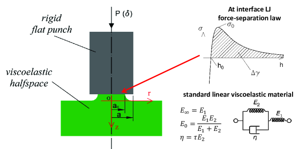
The adhesive behaviour of an axisymmetric rigid flat punch of radius in frictionless contact with a viscoelastic half-space is studied. For the linear viscoelastic material, the standard model is assumed, constituted by a spring placed in series with an element constituted by a dashpot and a spring in parallel (Fig. 1). The viscoelastic material has the relaxed Young’s modulus , instantaneous modulus 111This notation stems from frequency dependence notation of the complex modulus so that is the relaxed modulus. Other authors use the notation that is the instantaneous modulus as obtained at time in a relaxation test., and the relaxation time . The flat punch interacts with the viscoelastic substrate via a Lennard-Jones 3-9 force-separation law
| (7) |
where is the traction ( when tensile), is the gap and the equilibrium distance (the maximum tensile stress takes place at separation ). The gap function is written as
| (8) |
where is the radial coordinate, when the flat punch approaches the viscoelastic half-space, is the deflection of the viscoelastic half-space, which will depend on the loading history.
For elastic axisymmetric problems Greenwood1981 ; Feng
| (9) |
where is the composite elastic modulus of the two bodies in contact, is the pressure distribution (the minus sign account for the fact that we considered compressive tractions as negative), is the kernel function
| (10) |
and is the complete elliptic integral of the first kind of modulus . Hence, by using the elastic-viscoelastic correspondence principle in the form of Boltzmann integrals Chri , the normal displacements of the viscoelastic half-space at time , at location depend on the pressure history as
| (11) |
where is the dimensionless creep compliance function, which for a standard linear viscoelastic solid is
| (12) |
where .
Equation (11), discretized in time and space, is solved to provide the adhesive solution sought. The numerical scheme is alike that in Ref. Greenwood1981 ; Feng ; PapCia2020 except for accounting the viscoelastic behavior of the half-space. The radial domain is discretized with equally spaced elements, so that we have nodes where Eq. (11) is solved. From one node to the other a linear variation of the normal traction is assumed, which is usually referred as "the method of the overlapping triangles" Joh , and a sequential continuation algorithm is adopted in time, so that the solution at time is used as a guess for the next time step , where the time increment is kept fixed during the simulations. More details of the numerical implementation have been given in PapCia2020 .
3 From LEFM to uniform debonding behaviour
The contact of a rigid flat punch can be considered as an external crack that propagates at the interface under the action of a tensile load. If one assumes the punch to be rigid and the substrate elastic, neglecting friction, Maugis Maugis shows
| (13) |
where is the energy release rate, is the normal load and is the mode-I stress intensity factor. Imposing the Griffith energy balance Kendall1971 ; Maugis one finds the peeling force to be
| (14) |
where Correspondingly the pull-off stress is
| (15) |
which scales with the punch radius as , a well-known result of Linear Elastic Fracture Mechanics (LEFM). Clearly, cannot be larger then the theoretical strength of the interface . Hence, we define a lengthscale
| (16) |
and only for a punch of radius one expects LEFM based model to be accurate Kendall1971 , while for the cohesive limit is asymptotically obtained, where .
If the half-space is viscoelastic, we can consider it to behave as an elastic half-space in the limit of very slow and very fast unloading rate. In the latter case one obtains two different lengthscales which refer respectively to the slow and fast unloading limits (see also Ciavarella (ciava2022 ) for the analogous case of "short cracks"). Recalling , and using and one gets in dimensionless form
| (19) | |||
| (22) |
where .
4 Numerical results
We conducted a wide campaign of numerical investigations, whose results are reported in this section in dimensionless form, so that the following quantities have been defined
| (23) |
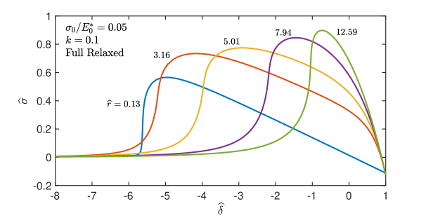
while is the pull-off stress. Unless differently stated, we used in our simulations and . First, let us consider the case of a punch of radius that is unloaded from a fully relaxed viscoelastic substrate starting from at different unloading rates , so that . Experimentally, this coincides with (i) indenting the viscoelastic substrate up to a prescribed indentation depth, (ii) waiting for a long dwell time so that the substrate fully relaxes, then (iii) unloading with a given (constant) displacement rate. The normalized unloading curves are shown in Fig. 2 in terms of mean normal stress versus remote indentation. As expected for a viscoelastic contact problem, the unloading rate strongly influences the unloading trajectory. For fast unloading, the substrate is stiff, hence a high load is required for the crack to advance. The two linear limit behaviour on unloading in Fig. 2 correspond to instantaneous and relaxed moduli, respectively. Clearly, pull-off stress increases with rate of unloading, but the dependence is non monotonic for the work of separation per unit area which is proportional to the area underneath the unloading curves (, is the indentation depth when the mean stress (or the load) vanishes).
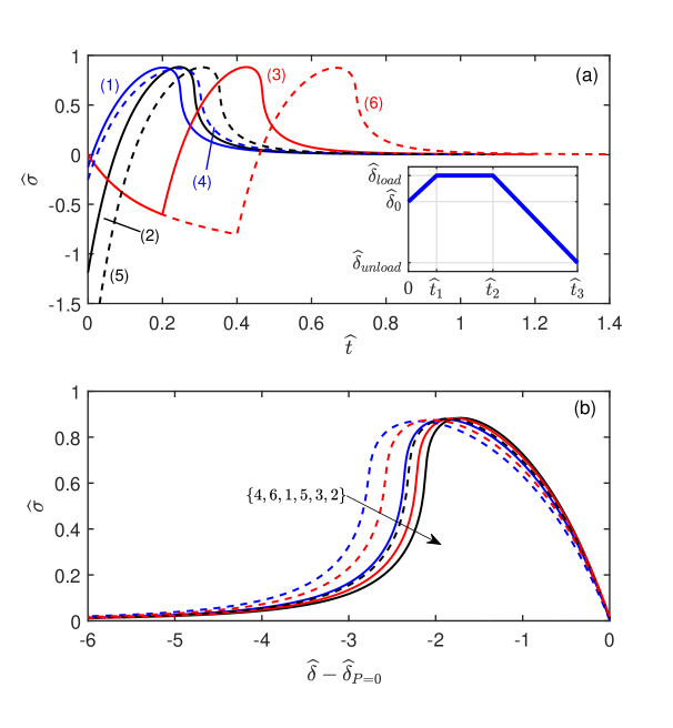
The response of a viscoelastic material is in general "history-dependent", as from the hereditary integral in Eq. (11). Curves in Fig. 2 were obtained unloading the flat punch from a fully relaxed substrate. To investigate the effect of the loading history, we run several numerical simulations, with different loading protocols, but fixing the unloading rate at . The simulations were conducted in displacement control and for we assumed a trapezoidal function, whose key parameters are defined in the inset of Fig. 3a. We introduce the dwell time , the loading rate and the unloading rate . Results in Fig. 3ab for each unloading curve correspond to the parameters in Table 1. We considered the cases when the punch is unloaded: (i) after very slow loading from a fully relaxed substrate (blue curves, (1,4)), (ii) after very rapid loading so that the substrate appears elastic with (black curves, (2,5)), (iii) after indenting the substrate at a constant loading rate (red curves, (3,6)). Notice that for the curves the loading phase is not shown. The maximum indentation depth was fixed equal to for the curves (solid lines) and for the curves (dashed lines). Despite the very different unloading trajectories, one notices that a key quantity such as the pull-off stress (Fig. 3ab) is almost unaffected by the loading history. Fig. 3b shows the same curves reported in 3a after shifting the horizontal axis by , which is the indentation depth at which the normal load vanishes during unloading, so that one can better appreciate the slight changes in the unloading trajectories. In the rest of the paper, unless differently stated, we will assume and
| Curve | |||||
|---|---|---|---|---|---|
| (1) - blue solid | very slow | ||||
| (2) - black solid | very fast | ||||
| (3) - red solid | |||||
| (4) - blue dashed | very slow | ||||
| (5) - black dashed | very fast | ||||
| (6) - red dashed |
Table 1 - Set of parameters that defines the loading protocol of the curves shown in Fig. 3ab. Notice that for all the simulations the unloading rate is fixed at and for all the simulations.
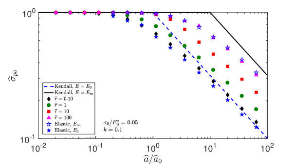
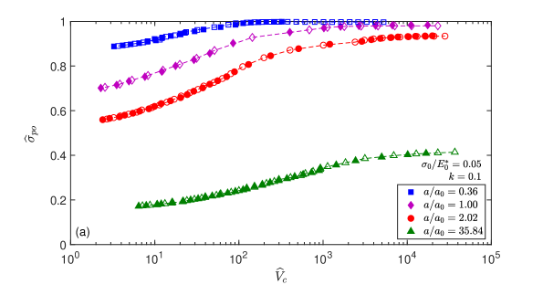
Having assessed that the loading history does not influence the pull-off stress , in Fig. 4 we investigated the variation of as a function of the normalized punch radius for four unloading rates (respectively black diamonds, green circles, red squares and pink triangles) and starting from a fully-relaxed substrate. For the cohesive limit is reached, where the pull-off stress is independent on both the loading rate and the punch radius and it approaches the theoretical value . For the curves follow the square root scaling imposed by LEFM, the pull-off stress increases with the unloading rate and the pull-off data remain bounded by the "slow" and "fast" limits dictated by the Kendall Kendall1971 solution (Eq. (19,22)), respectively blue-dashed and solid black lines. Notice that numerically we had to accomodate a small cohesive zone before we find the maximum force which sligthly reduced the peak force from the theoretical Kendall limit (see Fig. 4).
The variation of the pull-off stress as a function of the crack speed at pull-off is shown in Fig. 5a, for four different punch radii (respectively blue, purple, red and green curves) unloading either after a very slow loading phase (filled symbols, when unloading starts ) or after a very fast loading phase (empty symbols, when unloading starts ) and for , , . As suggested in Fig. 3, the pull-off stress is not affected by the loading history, moreover for small radii (blue curve) a change of orders of magnitude of the unloading rate resulted in a variation of the pull-off stress by only a as we are near the cohesive strength limit. Notice that we did not find an appreciable dependence of the pull-off stress on (not shown).
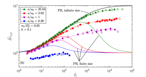
The same data shown in Fig. 5a are also reported in Fig. 5b, this time plotted as a normalized effective work of adhesion versus the crack speed at pull-off , being , or, in dimensionless form . The numerical results are compared with the prediction of Persson and Brener theory Persson2005 as extended for finite size systems (where finite size is implied by the difference between the size of crack ligament and the finite punch radius ) by Persson persson2017 slightly simplified by Ciavarella and Papangelo (Eq. (17) in Ref. CiaPap2021 ). Notice that in order to have a reasonable agreement with the numerical results, we had to use a shift factor on the crack velocity definition222In Eq. (17) of Ref. CiaPap2021 we used as a reference velocity , being . CiaPap2021 ; CCM2021 . The same color corresponds to the same ratio , while the grey curve is the reference to an infinite size system. The numerical results show that the effective work of adhesion increases monotonically with the crack speed in all cases. In particular, for large systems LEFM holds, hence for slow crack velocity , while at high velocity, we obtained an enhancement close to . For smaller radii, finite size effects come at play, but still increases monotonically with the crack speed. Moreover, for small radii, the normalized effective work of adhesion can be smaller than unity. This should not surprise as, even for a purely elastic problem, the pull-off stress is less than that expected from LEFM for small radii due to the transition towards the cohesive limit region which is equivalent to a reduced work of adhesion. In general, while we can say that there is a quantitative agreement with dissipation based theories for large radii, the results contrast both quantitatively and qualitatively for finite size, and in particular, there is no evidence of a maximum of load at intermediate speeds.
A key quantity to investigate is the work of separation , as it gives an estimate of the energy that is dissipated during the unloading phase. We obtained this quantity as a function of the normalized unloading rate for , respectively blue squares, red circles and green triangles (Fig. 6). Filled symbols refer to the case when the punch is unloaded after a very slow loading, while empty symbols refer to data obtained unloading after a very fast loading phase. The inset shows the work of separation as a function of the crack speed.
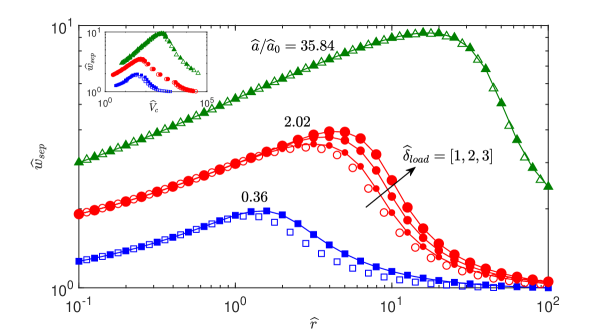
Notice that, contrary to the case of the pull-off stress and as suggested by Fig. 3, the work of separation shows a weak dependence on the loading rate, limited to small punch radius and intermediate unloading rates. For the case , and unloading from a fully relaxed substrate, several values of were tested, whose results are shown as red circles with the circle dimension increasing with . For intermediate rates, we find a slight dependence of on , which makes the picture a bit more elaborate than what happens for the pull-off stress. Importantly, while the pull-off stress increases monotonically with respect to the unloading rate, independently on the loading history, the work of separation retains a bell shape. Notice that for small punch radii the elastic limit at high and low velocity is , as we have a progressive detachment of the interface with uniform stress up to very large displacements, while in the LEFM region the elastic limit at high and low velocity is , because there is essentially a linear load-displacement curve up to the "brittle" rupture at the Kendall load and it can be easily shown that the gives , so that some strain energy must be released at the point of fracture. Hence, the problems are in all respects elastic both at very low and very high speeds, and dissipation is not the cause of the load enhancement at fast unloading, contrary to the classical de Gennes picture. The load increases of the ratio instantaneous to relaxed moduli, but the remote displacement decreases by the same ratio, hence the resulting area integral is the same at very low unloading rates, and at very high ones.
5 Extension of Maugis cohesive zone model
In this section, we attempt a generalization of the elastic cohesive model of Maugis Maugis (see also the work of Tang & Hui TangHui ) to the case of viscoelasticity. The problem of unloading a rigid axisymmetric flat punch from an elastic half-space of composite elastic modulus has been studied using a Dugdale cohesive law Maugis ; TangHui which showed that the peeling force is related to the radius of the ligament of the crack as follows
| (24) |
where we recall is the punch radius, while is the radius of the ligament of the crack which is a function of time, hence the cohesive stresses may exist in the annulus . The pull-off occurs when the separation at the crack mouth reaches the Critical Opening Distance (COD) in the Dugdale force-separation law, as any smaller radius would lead to a smaller force. Considering the crack profile this condition translates into TangHui
| (25) |
where equating the surface energy in a LJ force-separation law with that of a Dugdale model and having the same theoretical strength , gives . Solving Eq. (25) for one determines the critical radius of the ligament of the crack at pull-off and substituting into Eq. (24) the pull-off force is obtained. In the dimensionless formulation introduced before the equation for the normal stress is unaffected by the modulus
| (26) |
while the condition for the COD is modified for a viscoelastic half-space, by substituting the inverse of the elastic modulus with an effective compliance , with a characteristic time
| (27) |
In analogy with the suggestion of Schapery, we define being the width of the cohesive zone and the crack velocity333Schapery uses , for a constant stress (Dugdale) model.. For semi-infinite crack, and a Dugdale cohesive stress law, Schapery found
| (28) |
where we assumed, during propagation, the mode-I SIF is given by . In the numerical simulation, we used a standard linear viscoelastic material, hence
| (29) |
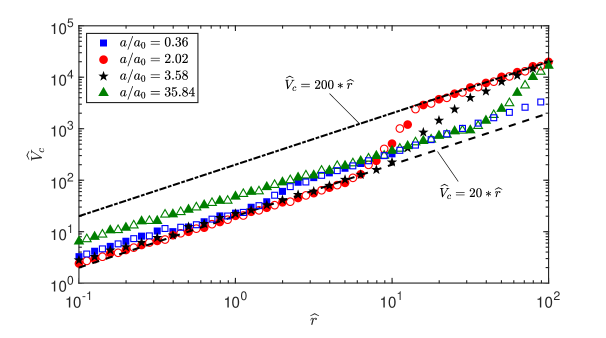
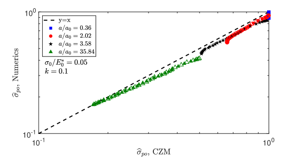
At every time-step we determined the crack position based on the location of the maximum adhesive stress at the interface, hence we estimated , the crack velocity at pull-off, and used this value in the Cohesive Zone Model (CZM, Eq. (29,27,26)) to determine the theoretical pull-off stress which was then compared with that obtained numerically in Fig. 7 for a set of punch radii (respectively blue squares, red circles, black stars, green triangles) unloading from a fully relaxed substrate (filled symbols, when unloading starts) or from a not-relaxed substrate (empty symbols, when unloading starts). Although small discrepancies appear with respect to the numerical data, the CZM provides a fairly good estimate of the pull-off stress, with deviations not larger than a between numerical and theoretical data.
As with semi-infinite crack theories, we have described the model as a function of the crack speed, which, in an adhesive experiment, is unlikely to be constant and has to be measured in numerical/real experiments, where generally the remote displacement rate is imposed. The relation between the external unloading rate with the crack speed at pull-off is shown in Fig. 8 for the same data as in Fig. 7. For small punch radii (blue squares) the behaviour is almost linear and a small deviation can be seen only around , while for we clearly found two linear regimes and a transition zone between the two linear dashed lines shown in Fig. 8, which perhaps may be used to roughly estimate the crack speed as a function of the loading rate.
6 Conclusions
In this work, we have studied the adhesive behaviour of a circular rigid flat punch that is placed in contact with a viscoelastic half-space. We showed that depending on the punch radius there exists a transition from a cohesive limit, where debonding happens at a uniform stress equal to the theoretical strength of the interface, to a regime that is governed by classical LEFM concepts, extended to the viscoelastic case. Our study has focused on two key quantities, such as the pull-off stress and the work of separation. We found that the pull-off stress is a monotonically increasing quantity of the unloading rate and is almost independent on the contact history. This is markedly different from the case of a Hertzian indenter which has been extensively studied AffVio2022 ; VioAff2022size ; VioAffRange and showed a strong influence on the preload. Indeed, we suggest here that the dependence on the loading history of the pull-off stress is geometry dependent. In our numerical simulations we also measured the work of separation as the energy per unit area that is dissipated to separate the contact. Indeed, in an attempt to interpret the maximum of load (and resulting instability) in the peeling experiments of Gent and Petrich gentpetrich , de Gennes deGennes proposed a theory of viscoelastic semi-infinite crack propagation based on dissipation away from the crack tip reaching a maximum at intermediate speeds. We found that has indeed a maximum at intermediate crack speed, but this does not correspond to a maximum of the load and hence dissipated energy cannot be directly used to determine the debonding load. Notice that in our geometry, where the flat punch is rigid, the stress intensity factor doesn’t need any geometrical correction factor as for example introduced in Vio2023 as it is always equal to where is initially the punch radius but then becomes the current size of the ligament of the crack. Hence our numerical results cannot be explained by a “corrected” Persson-Brener theory for infinite systems as suggested by Violano et al. Vio2023 for a finite viscoelastic plate geometry. Finally, we have proposed a cohesive zone model for debonding of a flat punch from a viscoelastic substrate, stemming from the elastic theory by Maugis Maugis (see also TangHui ), which proved to be reasonably good in terms of pull-off stress prediction. Unfortunately, in general we cannot impose externally the crack speed, but the remote displacement rate, and hence the theory only interprets data but is not predictive.
References
- (1) Giordano, G., Carlotti, M., & Mazzolai, B. (2021). A Perspective on Cephalopods Mimicry and Bioinspired Technologies toward Proprioceptive Autonomous Soft Robots. Advanced Materials Technologies, 6(12), 2100437.
- (2) Mazzolai, B., Mondini, A., Tramacere, F., Riccomi, G., Sadeghi, A., Giordano, G., … & Carminati, S. (2019). Octopus-Inspired Soft Arm with Suction Cups for Enhanced Grasping Tasks in Confined Environments. Advanced Intelligent Systems, 1(6), 1900041.
- (3) Giordano, G., Gagliardi, M., Huan, Y., Carlotti, M., Mariani, A., Menciassi, A., … & Mazzolai, B. (2021). Toward Mechanochromic Soft Material-Based Visual Feedback for Electronics-Free Surgical Effectors. Advanced Science, 8(15), 2100418.
- (4) Cacucciolo, V., Shintake, J., Kuwajima, Y., Maeda, S., Floreano, D., & Shea, H. (2019). Stretchable pumps for soft machines. Nature, 572(7770), 516-519.
- (5) Shui, L., Jia, L., Li, H., Guo, J., Guo, Z., Liu, Y., … & Chen, X. (2020). Rapid and continuous regulating adhesion strength by mechanical micro-vibration. Nature communications, 11(1), 1-7.
- (6) Arzt, E., Quan, H., McMeeking, R. M., & Hensel, R. (2021). Functional surface microstructures inspired by nature–from adhesion and wetting principles to sustainable new devices. Progress in Materials Science, 100778.
- (7) Lunni, D., Giordano, G., Pignatelli, F., Filippeschi, C., Linari, S., Sinibaldi, E., & Mazzolai, B. (2020). Light-assisted electrospinning monitoring for soft polymeric nanofibers. Scientific reports, 10(1), 1-12.
- (8) Lunni, D., Giordano, G., Sinibaldi, E., Cianchetti, M., & Mazzolai, B. (2018, April). Shape estimation based on kalman filtering: Towards fully soft proprioception. In 2018 IEEE International Conference on Soft Robotics (RoboSoft) (pp. 541-546). IEEE.
- (9) Asbeck, A., Dastoor, S., Parness, A., Fullerton, L., Esparza, N., Soto, D., … & Cutkosky, M. (2009). Climbing rough vertical surfaces with hierarchical directional adhesion. In 2009 IEEE International Conference on Robotics and Automation (pp. 2675-2680). IEEE.
- (10) Shintake, J., Cacucciolo, V., Floreano, D., & Shea, H. (2018). Soft robotic grippers. Advanced Materials, 30(29), 1707035.
- (11) Dahlquist, C. A. (1969). Pressure-sensitive adhesives. In Treatise on Adhesion and Adhesives. Vol.2 (ed. R. L. Patrick), pp.219-260. New York: Dekker.
- (12) Creton, C., & Ciccotti, M. (2016). Fracture and adhesion of soft materials: a review. Reports on Progress in Physics, 79(4), 046601.
- (13) Ciavarella, M., Papangelo, A., & McMeeking, R. (2021). Crack propagation at the interface between viscoelastic and elastic materials. Engineering Fracture Mechanics, 257, 108009.
- (14) Barquins, M., & Maugis, D. (1981). Tackiness of elastomers. The Journal of Adhesion, 13(1), 53-65.).
- (15) Gent, A. N. and Schultz, J., (1972), Effect of wetting liquids on the strength of adhesion of viscoelastic material, J. Adhes. 3(4), 281-294.
- (16) Gent, A. N., & Petrich, R. P. (1969). Adhesion of viscoelastic materials to rigid substrates. Proceedings of the Royal Society of London. A. Mathematical and Physical Sciences, 310(1502), 433-448.
- (17) Andrews, E. H., & Kinloch, A. J. (1974). Mechanics of elastomeric adhesion. In Journal of Polymer Science: Polymer Symposia (Vol. 46, No. 1, pp. 1-14). New York: Wiley Subscription Services, Inc., A Wiley Company.
- (18) Greenwood J A and Johnson K L (1981) The mechanics of adhesion of viscoelastic solids Phil. Mag. A 43 697–711
- (19) Maugis, D. (1992). Adhesion of spheres: the JKR-DMT transition using a Dugdale model. Journal of colloid and interface science, 150(1), 243-269..
- (20) R. Rivlin , Paint Technol. (1944), 9 , 215. DOI: 10.1007/978-1-4612-2416-7_179
- (21) Williams, M. L.; Landel, R. F.; Ferry, J. D. (1955) The Temperature Dependence of Relaxation Mechanisms in Amorphous Polymers and Other Glass-Forming Liquids. Journal of the American Chemical Society, 77, 3701-3707.
- (22) Gent, A. N., & Petrich, R. P. (1969). Adhesion of viscoelastic materials to rigid substrates. Proceedings of the Royal Society of London. A. Mathematical and Physical Sciences, 310(1502), 433-448.
- (23) Ceglie, M., Menga, N., & Carbone, G. (2022). The role of interfacial friction on the peeling of thin viscoelastic tapes. Journal of the Mechanics and Physics of Solids, 159, 104706.
- (24) Rice, J. R. (1978). Mechanics of quasi-static crack growth (No. COO-3084-63; CONF-780608-3). Brown Univ., Providence, RI (USA). Div. of Engineering.
- (25) Graham, G. A. C. (1969) Two extending crack problems in linear viscoelasticity theory, Q. Appl. Math., 27, 497–507
- (26) Schapery, R. A. (1975) A theory of crack initiation and growth in viscoelastic media. Int. J. Fracture, 11, (Part I) 141–59
- (27) Schapery, R. A. (1975). A theory of crack initiation and growth in viscoelastic media II. Approximate methods of analysis. Int. J. Fracture, 11(3), 369-388.
- (28) Knauss WG (1973b) On the steady propagation of a crack in a viscoelastic sheet: experiments and analysis. In: Kausch HH, Hassel IA, Jaffe RE (eds) Deformation and fracture of high polymers. Proceedings of the same-name 1972 conference in Kronberg, Germany. Plenum Press, New York, London, pp 501–541
- (29) de Gennes, P. G. (1996). Soft adhesives. Langmuir, 12(19), 4497-4500.
- (30) Persson, B. N. J., & Brener, E. A. (2005). Crack propagation in viscoelastic solids. Physical Review E, 71(3), 036123.
- (31) Hui, C. Y., Zhu, B., & Long, R. (2022). Steady state crack growth in viscoelastic solids: A comparative study. Journal of the Mechanics and Physics of Solids, 159, 104748.
- (32) Ciavarella, M., & Papangelo, A. (2021). Effects of finite thickness on crack propagation in viscoelastic materials. Engineering Fracture Mechanics, 248, 107703.
- (33) Ciavarella, M., Papangelo, A., & McMeeking, R. (2022) On transient and steady state viscoelastic crack propagation in a double cantilever beam specimen. International Journal of Mechanical Sciences, 229, 107510. DOI: 10.1016/j.ijmecsci.2022.107510
- (34) Ciavarella, M., Cricrì, G., & McMeeking, R. (2021). A comparison of crack propagation theories in viscoelastic materials. Theoretical and Applied Fracture Mechanics, 116, 103113.
- (35) Xu, D. B., Hui, C. Y., & Kramer, E. J. (1992). Interface fracture and viscoelastic deformation in finite size specimens. Journal of Applied Physics, 72(8), 3305-3316.
- (36) Ciavarella, M. (2021). An upper bound for viscoelastic pull-off of a sphere with a Maugis-Dugdale model. The Journal of Adhesion, 1-14.
- (37) Afferrante, L., & Violano, G. (2022). On the effective surface energy in viscoelastic Hertzian contacts. Journal of the Mechanics and Physics of Solids, 158, 104669.
- (38) Violano, G., & Afferrante, L. (2022). Size effects in adhesive contacts of viscoelastic media. European Journal of Mechanics-A/Solids, 104665.
- (39) Violano, G., & Afferrante, L. (2022). On the long and short-range adhesive interactions in viscoelastic contacts. Tribology Letters, 70(3), 1-5.
- (40) Müser, M. H., & Persson, B. N. (2022). Crack and pull-off dynamics of adhesive, viscoelastic solids. Europhysics Letters, 137(3), 36004.
- (41) Tang, T., & Hui, C. Y. (2005). Decohesion of a rigid punch from an elastic layer: Transition from “flaw sensitive” to “flaw insensitive” regime. Journal of Polymer Science Part B: Polymer Physics, 43(24), 3628-3637.
- (42) Feng, J. Q. (2000). Contact behavior of spherical elastic particles: a computational study of particle adhesion and deformations. Colloids and Surfaces A: Physicochemical and Engineering Aspects, 172(1-3), 175-198.
- (43) Christensen, R. (2012). Theory of viscoelasticity: an introduction. Elsevier.
- (44) Persson, B. N. J. (2017). Crack propagation in finite-sized viscoelastic solids with application to adhesion. EPL (Europhysics Letters), 119(1), 18002.
- (45) Papangelo, A., & Ciavarella, M. (2020). A numerical study on roughness-induced adhesion enhancement in a sphere with an axisymmetric sinusoidal waviness using Lennard–Jones interaction law. Lubricants, 8(9), 90.
- (46) Ciavarella, M., Cricrì, G., & McMeeking, R. (2021). A comparison of crack propagation theories in viscoelastic materials. Theoretical and Applied Fracture Mechanics, 116, 103113.
- (47) Johnson, K. L., (1987). Contact mechanics. Cambridge university press.
- (48) Kendall, K. (1971). The adhesion and surface energy of elastic solids. Journal of Physics D: Applied Physics, 4(8), 1186.
- (49) Ciavarella, M. (2022). Viscoelastic short cracks propagation. Engineering Fracture Mechanics, 264, 108276.
- (50) Violano, G., De Carolis, S., Palmieri, M. E., Carbone, G., Tricarico, L., Demelio, G. P., & Afferrante, L. (2023). Crack propagation in viscoelastic finite-sized solids: theory and experiments. In IOP Conference Series: Materials Science and Engineering (Vol. 1275, No. 1, p. 012043). IOP Publishing.
Statements & Declarations
Funding
A.P. was supported by the European Union (ERC-2021-STG, “Towards Future Interfaces With Tuneable Adhesion By Dynamic Excitation” — SURFACE, Project ID: 101039198, CUP: D95F22000430006). Views and opinions expressed are however those of the authors only and do not necessarily reflect those of the European Union or the European Research Council. Neither the European Union nor the granting authority can be held responsible for them. A.P. was partially supported by Regione Puglia (Italy), project ENOVIM (CUP: D95F21000910002) granted within the call ”Progetti di ricerca scientifica innovativi di elevato standard internazionale” (art. 22 della legge regionale 30 novembre 2019, n. 52 approvata con A.D. n. 89 of 10-02-2021, BURP n. 25 del 18-02-2021). A.P. and M.C. acknowledge support by the Italian Ministry of University and Research (MUR) under the programme “Department of Excellence” Legge 232/2016 (Grant No. CUP - D93C23000100001).
Data availability
The dataset generated for this article is availbale at DOI: 10.5281/zenodo.7757174
Competing Interests
The authors have no relevant financial or non-financial interests to disclose.
Author Contributions
A.P. and M.C. contributed equally to this work.
Published Version
This article was published in Tribology Letters, Springer, DOI: 10.1007/s11249-023-01720-9