Electronic structure, magnetic properties, spin orientation,
and doping effect in Mn3Si2Te6
Abstract
The layered material Mn3Si2Te6, with alternating stacking honeycomb and triangular layers, is attracting considerable attention due to its rich physical properties. Here, using density functional theory and classical Monte Carlo (MC) methods, we systematically study this system with the electronic configuration. Near the Fermi level, the states are mainly contributed by Te orbitals hybridized with Mn orbitals, resembling a charge transfer system. Furthermore, the spin orientations of the ferrimagnetic (FiM) ground state display different conductive behaviors when along the plane or out-of-plane directions: insulating vs. metallic states. The energy difference between the FiM [110] insulating and FiM [001] metallic phases is very small( meV/Mn). Changing the angle of spin orientation from in-plane to out-of-plane directions, the band gaps of this system are gradually reduced, leading to an insulator-metal transition, resulting in an enhanced electrical conductivity, related to the colossal angular magnetoresistance (MR) effect. Although the three main magnetic couplings were found to be antiferromagnetic, overall the ground state is FiM. In addition, we also constructed the magnetic phase diagram using the classical spin model studied with the MC method. Three magnetic phases were obtained including antiferromagnetic order, noncollinear spin patterns, and FiM order. Moreover, we also investigated the Se- and Ge- doping into the Mn3Si2Te6 system: the FiM state has the lowest energy among the magnetic candidates for both Se- or Ge- doped cases. The magnetic anisotropy energy (MAE) decreases in the Se-doped case because the Mn orbital moment is reduced as the doping increases. Due to the small spin-orbital coupling effect of Se, the insulator-metal transition caused by the spin orientation disappears in the Se-doped case, resulting in an insulating phase in the FiM [001] phase. This causes a reduced colossal angular MR. However, both the MAE and band gap of the Ge-doped case do not change much with increasing doping . Our results for Mn3Si2Te6 could provide guidance to experimentalists and theorists working on this system or related materials.
I I. Introduction
Because of their rich physical properties, layered correlated systems with transition atoms have attracted considerable attention for decades in the condensed mater and material science communities Imada:rmp ; Moreo:science ; Dagotto:science ; Zhou:rmp ; Cao:rpp ; Varignon:nc19 ; Zhang:prb20 ; Takayama:jpsj ; Do:prb22 . In those systems, many exotic physical properties are induced by the couplings between the charge, spin, orbital, and lattice degrees of freedom, leading to colossal magnetoresistance (CMR) and electronic phase separation Dagotto:rp ; Tokura:rpp ; Wu:prl01 ; Ward:np ; Lin:prl18 ; miao:pnas2020 , magnetoelectricity Sergienko:prb ; Sergienko:prl ; Brink:jpcm ; Dong:nsr , orbital/charge ordering Balachandran:prb13 ; Varignon:prb17 ; Pandey:prb21 ; Lin:prm21 , and high-temperature superconductivity Dagotto:rmp94 ; Dagotto:Rmp ; Dai:rmp ; Li:nature .
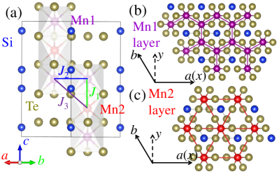
Recently, the layered material Mn3Si2Te6 with mixed honeycomb and triangular layers has received considerable attention because of its interesting properties May:prb17 ; Sala:prb22 ; Liu:prb21 ; Ni:prb21 ; Seo:nature ; Wang:prb22 ; Zhang:nature ; Ye:arxiv ; Mijin:arxiv . Mn3Si2Te6 displays a trigonal structure with space group (No. 163), where Mn has two different atomic positions May:prb17 , as shown in Fig. 1. The MnTe6 octahedra are edge-sharing connected or are well-separated with two Mn1 and Mn2 sites in the plane, respectively, leading to an alternately stacking of Mn-honeycomb and Mn-triangular layers along the [001] direction. The Si atoms form Si-Si dimers along the -axis (see Fig. 1).
Neutron diffraction experiments found that Mn3Si2Te6 has a ferrimagnet (FiM) order below K, with the spins lying along the [110] direction ( plane) due to strong anisotropy May:prb17 . Furthermore, they also found that the largest antiferromagnetic (AFM) coupling is between nearest-neighbor (NN) Mn-Mn sites along the -axis, while the in-plane coupling with the next-nearest neighbor (NNN) distance of the Mn-Mn bond is smaller than the next-next-nearest neighbor (NNNN) . Moreover, inelastic neutron scattering was applied to the analysis of this FiM ground state in combination with the study of the spin-wave dispersion of the magnetic Hamiltonian Sala:prb22 .
In Mn3Si2Te6, the Mn ions are in a valence with a configuration, leading to a quenched orbital moment, resulting in a and state. Considering the half-filling electronic configuration of Mn2+, the Mn should in principle favor AFM coupling, which is not the case experimentally. Hence, two simple questions naturally arise. What is the origin of the FiM order? What other interesting magnetic states can be obtained by considering the competition between the several magnetic couplings?
In addition, the CMR effect was found in Mn3Si2Te6 by several research groups Liu:prb21 ; Ni:prb21 ; Wang:prb22 ; Zhang:nature ; Seo:nature . The reported large negative CMR and thermal conductivity indicates the presence of strong spin-lattice coupling in this material Liu:prb21 . Furthermore, the CMR occurs only when the magnetic field is applied along the magnetic hard axis and is surprisingly absent when the magnetic field is applied along the magnetic easy axis where magnetization is fully saturated Ni:prb21 . Meanwhile, pressure suppresses the insulating state and CMR effect in Mn3Si2Te6, leading to a semiconductor-metal transition between and GPa, as well as a possible structural transition at GPa Wang:prb22 . Recently, chiral orbital currents were also reported in this system Zhang:nature .
It was also proposed that the colossal angular magnetoresistance (MR) effect could be caused by a topological nodal-line degeneracy of spin-polarized bands in this material Seo:nature . Introducing carriers by doping in the system, the colossal angular MR effect slightly decreases, or is strongly suppressed at K, for the Ge- or Se- doped cases, respectively Seo:nature . This interesting colossal angular MR physics could be related to the rapidly reduced band gap by changing the angle of spin orientation between the [110] to the [001] direction. In this case, will the anisotropy change for different doping carriers? How do other physical properties, such as the magnetic ground state and anisotropic energy, change under different doping effects? To better understand all these interesting issues, a detailed theoretical study is needed for a proper physical description of this system.
Hence, a systematic study of the physical evolution of Mn3Si2Te6 is presented here using first-principles density functional theory (DFT) and classic Monte Carlo (MC) calculations. Based on ab initio DFT, we found that the FiM state is the most likely ground state, in agreement with neutron scattering. In addition, the states near the Fermi level are mainly contributed by the Te states hybridized with the Mn orbitals, leading to a charge transfer system. Furthermore, the FiM state with the spin order lying in different directions is found to display different behaviors: insulating state in the plane and metallic state in the out-of-plane direction. Because those two phases only have a small energy difference ( meV), the FiM [110] insulating and FiM [001] metallic states could compete under external fields, leading to the CMR effect. By changing the angle between the [110] and [001] directions, the band gap is rapidly reduced, leading to an insulator-metal transition, resulting in the observed colossal angular MR effect. In addition, we also constructed the magnetic phase diagram varying magnetic couplings in a classical spin model using the MC method. Phase competition was observed by this procedure as well.
Moreover, we also investigated the Se- or Ge-doped in the Mn3Si2Te6 system, in the regime where the FiM state has the lowest energy among the magnetic candidates. We found that the spin still prefers to lie in the plane for both the Se- or Ge-doped cases. As the doping level increases, the magnetic anisotropy energy (MAE) decreases in the Se-doped case due to the reduced orbital moment of Mn. Furthermore, the FiM state with spin lying in the -axis displays strong insulating behavior, leading to a reduced colossal angular MR.
II II. Calculation Method
II.1 A. DFT Method
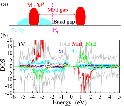
In the present study, we employ first-principles DFT calculations performed by using the Vienna ab initio simulation package (VASP) software Kresse:Prb ; Kresse:Prb96 ; Blochl:Prb with the projector augmented wave (PAW) method. Electronic correlations were considered by using the generalized gradient approximation (GGA) with the Perdew-Burke-Ernzerhof (PBE) potential Perdew:Prl . The -point mesh adopted was for the conventional cell of the structure. This -point mesh was tested explicitly to confirm it produces converged energies. Furthermore, for the calculation of the density of state (DOS), the -point mesh was increased to . The plane-wave cutoff energy used was eV. Here, we considered several different collinear magnetic configurations, see Fig. 1(d). These states do not break the crystal symmetry (No. 163). In addition, on-site interactions were considered by using the local spin density approach (LSDA) plus by using the Dudarev’s rotationally invariant formulation Dudarev:prb . Both the lattice constants and atomic positions were fully relaxed until the Hellman-Feynman force on each atom was smaller than eV/Å for all spin configurations. All the crystal structures were visualized with the VESTA code Momma:vesta .
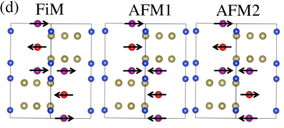
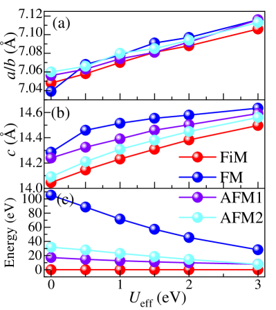
Based on the (No. 163) structure of Mn3Si2Te6, we compared the results of optimized crystal lattice constants using different values of (see Appendix). Our optimized lattice constants are , Å for the FiM spin state at eV, close to the low-temperature experimental results (, Å Ni:prb21 ). Furthermore, the pressure-induced insulator-metal transition was also experimentally observed in Mn3Si2Te6 between and Gpa Wang:prb22 . Based on the LSDA+ eV calculations, we found the critical pressure for the insulator-metal transition to be about Gpa [see Fig. 2(a)], also close to the experimental observation ( to Gpa) Wang:prb22 . However, this critical pressure is about Gpa for the LSDA+ eV calculations, as shown in Fig. 2(b). At ambient conditions, an insulator-metal transition was also reported in Mn3Si2Te6 by switching the magnetic field from the plane to the -axis Seo:nature . Our results at large could not reproduce this phase transition. For example, we obtained that the band gaps are and meV for the plane or -axis, respectively, at eV. In addition, we also tested the PBE functional revised for solids (PBEsol) Perdew:Prl08 with eV, as used in Ref. Wang:prb22 . The optimized lattice parameters are , Å and the calculated critical pressure of insulator-metal transition is Gpa [see Fig. 2(c)]. Furthermore, the calculated band gaps are and meV for the plane or -axis, respectively, at eV with PBEsol potential. Based on these comparisons between theoretical and experimental results, then we employed the value eV in our calculations, which is sufficient to describe this system. Overall, we conclude that the main physical results of our study are not significantly affected by the value of , such as the presence of the ferrimagnetic ground state, the reduced band gap of different orientations, and the magnetic properties under doping effects. Additional discussion about the role of is presented in the Appendix and supplemental materials Supplemental .
II.2 B. Monte Carlo Method
To better understand qualitatively the magnetic properties of this system, we used a simple classic spin model, as described below:
| (1) | |||||
where , , and are the exchange interactions between NN, NNN, and NNNN spin pairs, respectively, as shown in Fig. 1(a). The reason for using an model, instead of Heisenberg model, is because Mn3Si2Te6 has an easy plane with the same energy in that plane.
The Markov chain MC method with the Metropolis algorithm was employed to construct the magnetic phase diagram of this model using a unit cells lattice with 6 sites in each unit cell, namely 9600 sites in total, within periodic boundary conditions. Different lattice sizes, such as and , gave out similar results. In the MC simulation, 1 MC steps were used for thermal equilibrium at low temperature (). For all simulated temperatures (), the acceptance ratio of MC updates was kept at about by adjusting the updating windows for the spin vectors to avoid being trapped in metastable states and improve the simulation efficiency Lin:fop ; Zhang:prm ; Lin:prm17 . Furthermore, the final real-space spin patterns for different parameters were obtained from the low- MC results followed by energy optimization. By this procedure, imperfections in the spin pattern were further reduced.
III III. Results
III.1 A. Magnetism and electronic structure
Under ambient conditions, the energies of various magnetic states for the relaxed structures are summarized in Table 1. The FiM state has the lowest energy among all the candidates, in agreement with neutron experiments May:prb17 . For the FiM state, the calculated local magnetic moments of Mn are about and /Mn for the Mn1 and Mn2 sites, respectively, corresponding to the high-spin state of the Mn configuration. In addition, the calculated Mn-orbital moments are /Mn1 and /Mn2, where such a small orbital moment could induce the anisotropy. All collinear AFM states display insulating behavior with a small band gap, as shown in Table 1.
| FiM | FM | AFM1 | AFM2 | |
|---|---|---|---|---|
| 7.058 | 7.068 | 7.063 | 7.066 | |
| 14.145 | 14.286 | 14.325 | 14.221 | |
| E(LSDA+) | 0 | 88.54 | 14.76 | 27.91 |
| (Mn1) | 4.240 | 4.318 | 4.219 | 4.239 |
| (Mn2) | 4.114 | 4.320 | 4.182 | 4.240 |
| E[110] | 0 | 86.67 | 14.48 | 27.05 |
| Gap | 161.2 | 0 | 561.3 | 262.6 |
As already explained, our optimized lattice constants are , Å for the FiM spin state, close to the experimental values at low temperature (, Å) Ni:prb21 . In addition, the optimized in-plane lattice constants are very close for the different magnetic orders and nonmagnetic states ( Å). However, the -value is significantly reduced in the nonmagnetic state: Å, which is Å shorter than the value of the FiM configuration. At high temperature, above the transition temperature , no huge changes in the -lattice constant were observed experimentally May:prb17 ; Liu:prb21 . For this reason, short-range spin correlations should still be present above . In fact, previous diffuse neutron scattering experiments for Mn3Si2Te6 also revealed the existence of short-range spin correlations well above at 150 Ye:arxiv and 330 K May:prb17 , indicating possible short-range order or the persistence of correlated excitations in the paramagnetic region.
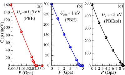
In Mn3Si2Te6, the Mn-ions have a valence, leading to a electronic configuration with five half-filled orbitals. Without any interactions, the Mn states display strong itinerant behavior hybridized with the Te orbitals. By introducing the Hubbard interaction , the five half-filled Mn- orbitals should be Mott-localized with a small bandwidth, opening a Mott gap. Furthermore, the Te states are usually extended in real space Zhang:prb20-2 , leading to wide bands with large bandwidth. For these reasons, Mn3Si2Te6 is more likely a charge-transfer system, with the expected local DOS schematically shown in Fig. 3(a). Then, the band gap of this system depends on the energy gap between empty Mn’s and fully occupied Te’s state, as shown in Fig. 3(a).
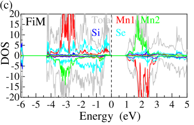
Next, we also calculated the DOS of the FiM state of Mn3Si2Te6 using LSDA+ ( eV), as displayed in Fig. 3(b). Note that the spin dependence of the correlation energy density is already considered in the LSDA portion. Hence, the additional effective of the DFT calculations is different from the Hubbard in the standard model Hamiltonian calculations: the value of of DFT calculations is always smaller than the value of of the Hubbard Hamiltonian model.
According to the DOS, the states near the Fermi level are mainly contributed by the Te orbitals, partially hybridized with the Mn- orbitals. The Te orbitals display a strong extended behavior with a large bandwidth. Furthermore, the Mn’s states display a Mott-localized behavior with a large Mott gap, where those occupied states are mainly located at lower energy regions from to eV [see Fig. 3(b)]. Then, the band gap of this system dramatically decreases to eV, where this gap is caused by the occupied Te and unoccupied Mn states. In this case, this general physical picture could intuitively be used to understand the semiconducting behavior with a small band gap in the experiment Seo:nature although the Mn orbitals form a large Mott gap. In addition, the Mn states still display Mott-localized behavior with increasing Mott gap as the values of increases [See Fig. S1(b)].
To better understand this physical picture, we also calculated the DOS of the FiM state of Mn3Si2Se6 based on the same crystal lattice constants of Mn3Si2Te6 using LSDA+ ( eV), as displayed in Fig. 3(c). Compared with Mn3Si2Te6, the Se’s , and Mn’s orbitals are more localized, leading to a smaller bandwidth than for the Te case. Then, using the same parameters ( eV) and crystal structure lattice constants, the calculated band gap of Mn3Si2Se6 increases to about eV. Hence, all the results we obtained for the DOS support the charge-transfer picture, as already analyzed in previous paragraphs.
By introducing the SOC effect, the Te bands would split, leading to different physical properties for different spin orientations, as will be discussed in the next section.
III.2 B. Spin orientation
Turning on the SOC, we found that the spin quantization axis points to the plane but with only a very small difference in energy compared to the [001] direction, indicating that the spin prefers to be in the plane. In addition, the MAE (E[110]-E[001]) is calculated to be meV/Mn for the FiM state, by comparing the energy difference between [110] and [001]. This small energy difference arises from the small SOC of the Mn ions. As discussed in the previous section, the calculated orbital moments of Mn are quite small: /Mn1 and /Mn2, respectively. Then, this small orbital moment contributes to the small difference in the anisotropy energy ( meV). In principle, an external magnetic field could rotate the spin from the plane to the [001] direction, and then flip the AFM spins to FM order if the energy differences between those states are small.
In the well-known CMR materials, such as the hole-doped manganites La1-xCaxMnO3, the phase separation mechanism plays a key role to understand the CMR effect, which is caused by the competition between the AFM insulating and FM metallic phases, both induced by the double exchange interaction Dagotto:rp ; Salamon:rmp . However, in Mn3Si2Te6, the FM metallic state has much higher energy than the AFM insulating state (see Table 1), indicating that via magnetic external fields it will be difficult to flip AFM spins to a FM order. In this case, the origin of the CMR effect of Mn3Si2Te6 should be different from that of typical hole-doped manganites.
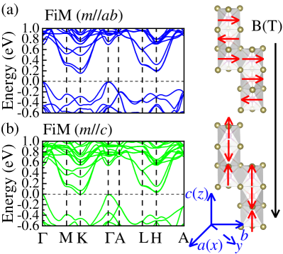
Introducing the SOC effect, the Te-occupied bands start to split with different nodal-line degeneracy in different spin orientations of the Mn spins, as displayed in Fig. 4. Note that the topological nodal-line degeneracy physics of this compound has been studied in detail in a recent publication Seo:nature . The FiM [110] state, with spin moments lying in the -plane, displays a semiconducting behavior with an indirect gap meV [see Fig. 4 (a)]. For the FiM [001] state with the spin oriented along the -axis, the band structure indicates a metallic phase, as shown in Fig. 4(b). Hence, the insulator-metal transition occurs by switching the spin orientation from the [110] plane to the [001] direction. Due to the small energy difference between [110] and [001] directions ( eV), this insulator-metal transition could be induced by an external magnetic field along the -axis.
This analysis suggests that the FiM [110] insulating and FiM [001] metallic phases could compete due to the small energy difference scale, which could qualitatively explain the observed CMR effect in experiments Liu:prb21 ; Ni:prb21 ; Seo:nature ; Wang:prb22 . Hence, the origin of the CMR effect of Mn3Si2Te6 should be related to the competition between insulating and metallic phases in the same magnetic state but different spin orientations. This behavior is similar to the observed CMR in EuCd2As2, where the competition among phases is also induced by the spin orientations with competing energies between magnetic topological insulating, trivial insulating, and Weyl semimetal phases Du:qm .
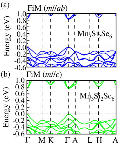
Furthermore, this insulator-metal transition with a reduced band gap induced by the spin orientations ( to meV) is caused by the nodal-line structure of Te’s -bands, also related to the SOC effect. If the SOC strength is reduced, the change in the ([110]-[001]) band gap between in-plane and out-plane directions should be reduced as well. Hence, we also calculated the band structures of the FiM state of Mn3Si2Se6 for different spin orientations based on the same crystal structure of Mn3Si2Te6, because the SOC effect of Se is smaller than for Te atoms. As displayed in Fig. 5, the change in the band gap between the [110] and [001] directions is reduced to about meV, as expected. The CMR and colossal angular MR effects of this system are related to the change of bands gaps of different spin orientations, where the reduced value of the band gap from in-plane to out-plane directions is decided by the value of the SOC. Hence, the CMR or colossal angular MR effects should be strongly suppressed in Mn3Si2Se6.
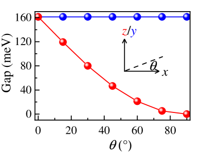
To better understand the spin orientation effet, we simulated the switching “path” in the and out of plane by changing the angle between the and axes. Changing the angle (corresponding to different spin quantization axis) in the plane (corresponding to the crystal plane), the energy and the band gap are identical, independent of the angle [See Fig. S2 and Fig. 6]. In addition, the band gap rapidly is reduced by changing the spin quantization axis from the to the -axis, as displayed in Fig. 6, consistent with the large resistance reduction as the magnetic field orientation is varied Seo:nature . Note that the insulator-metal transition of spin orientation is a “gradual” transition as spin angle changes, not a ”sharp” phase transition. This insulator-metal transition caused by the angle could also explain the colossal angular MR observed in experiments Seo:nature .
III.3 C. Ferrimagnetic state and magnetic phase diagram
Based on the optimized crystal lattice of the FiM state, we mapped the DFT energy into a classical model to obtain three magnetic exchange couplings , assuming the magnitude of the spins is considered as for simplicity. Note that those values of are calculated by mapping the DFT energies of four different states (FiM, AFM1, AFM2, and FM) to the classic spin model.
At eV, we obtained that the three magnetic couplings are , and , all in units of meV. The coupling involving nearest-neighbor Mn-Mn distances provides the strongest AFM magnetic exchange coupling, much larger than and . In addition, the between NNN Mn-Mn sites is also AFM but smaller than the AFM with NNNN Mn-Mn distance, in agreement with previous calculations May:prb17 ; Seo:nature . In this case, those three AFM couplings could lead to strong frustration due to the competition in a triangular geometry. Note that our qualitative results are approximately independent of the choice of . For the benefit of the readers, based on the optimized crystal lattice of the FiM state, we also evaluated the three magnetic exchange coupling vs. , as summarized in Table 2.
| / | / | ||||
|---|---|---|---|---|---|
| 0 | -38.6 | -12.4 | -15 | 0.321 | 0.389 |
| 0.5 | -33.8 | -11.4 | -13.4 | 0.337 | 0.396 |
| 1 | -27.7 | -9.1 | -10.9 | 0.329 | 0.394 |
| 1.5 | -22.7 | -7.1 | -8.7 | 0.313 | 0.383 |
| 2 | -18.3 | -5.6 | -6.8 | 0.306 | 0.372 |
| 3 | -12.6 | -3.2 | -3.8 | 0.254 | 0.302 |
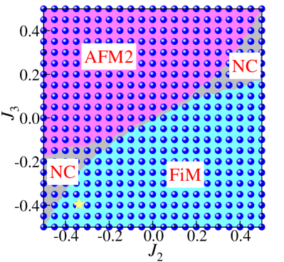
Next, we calculated the magnetic phase diagram varying , based on the classical spin model using MC techniques (spin patterns are provided in real space). For the path (NN Mn-Mn sites) along the -axis, the magnetic coupling should be the strongest AFM due to the strong overlap of orbitals, where the local basis is considered, as shown in Fig. 1. Hence, we fixed the NN path to be AFM with and the NNN and NNNN were both considered to be either AFM or FM, by changing the values from -0.50 to 0.50. We found two dominant phases, involving collinear AFM2 and FiM spin orders, as shown in Fig. 7. In addition, a noncollinear (NC) spin pattern, to be shown explicitly below, was also obtained at the boundaries between the AFM2 and FiM phases (see Fig. 7). It should be noted that the boundaries between different phases should be considered only as crude approximations. However, the existence of the three different phase regions was clearly established, even if the boundaries are only estimations. We believe our theoretical magnetic phase diagram should encourage a more detailed experimental study of this compounds or related systems, for example by varying the chemical composition.
In the unit cell of the Mn3Si2Te6 lattice, there are 12 and 6 spin pairs along the or paths, respectively. Hence, the region of stability of the different magnetic phases is mainly decided by the sign of . If (FM interaction), the AFM2 phase is the dominant phase in our MC phase diagram. For example, the real-space spin pattern at and clearly displays antiferromagnetic order, as shown in Fig. 8 (a) (obtained from low- MC plus optimization). Furthermore, the NC spin order was obtained in some regions due to the strong competition between and if the also is a FM coupling and larger than [see, as an example, the real-space spin pattern at = 0.30 and = 0.46 in Fig. 8(b)].
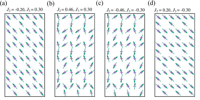
In addition, a similar NC order was also obtained if the AFM could compete with AFM , such as at = -0.46 and = -0.30, with the NC pattern displayed in real space in Fig. 8(c). In the and regions (AFM and FM ), the FiM phase is stable, as displayed is Fig. 7. The example = 0.20 and = -0.30 in Fig. 8(d) clearly shows that the real-space spin pattern corresponds to FiM order. Considering the calculated magnetic coupling values (, and meV) Liechtensteincontext , the real material Mn3Si2Te6 is located inside the FiM region in our MC phase diagram (see yellow star in Fig. 7), in agreement with experiments.
III.4 D. Doping effect
To better understand the physical properties under Se or Ge doping in Mn3Si2Te6, we employed the virtual crystal approximation (VCA) to simulate the doping effect, technique widely used in the electronic structure context Bellaiche:Prb ; Ramer:Prb ; Zhang:prb21 . Here, both the lattice constants and atomic positions were fully relaxed with different spin states, for different Se or Ge doping levels.
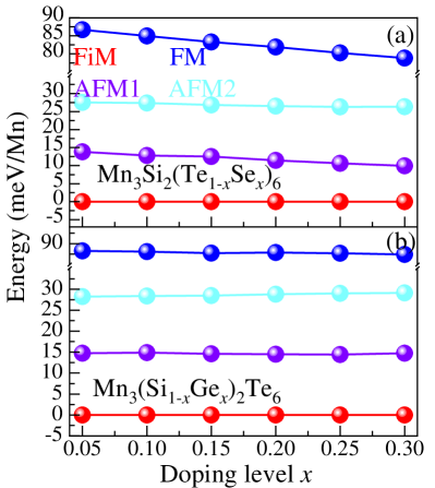
For both Mn3Si2(Te1-xSex)6 and Mn3(Si1-xGex)2Te6, the FiM state has the lowest energy among all magnetic candidates at the doping levels we studied, as displayed in Fig. 9. In addition, the energy differences of different magnetic states do not change much. Then, we conclude that the magnetic transition temperatures at small doping of Se or Ge would not change much either, in agreement with experimental results for the magnetic susceptibility of the undoped, Se-doped, and Ge-doped cases Seo:nature . Furthermore, the spin quantization axis always points along the crystal plane but with only a small difference in energy with respect to the -axis ([001] direction), indicating that the spin still favors lying in the crystal plane, for both the Ge- and Se-doped cases.
As the doping level increases, the MAE (E[110]-E[001]) slightly decreases from meV/Mn () to meV/Mn () in the Se-doped case, while it is almost unchanged in the Ge-doped case, as displayed in Fig. 10(a). This is reasonable. As the doping increases in Mn3Si2(Te1-xSex)6, the orbital moments of Mn decrease to /Mn for the Mn1 and Mn2 sites, respectively. Because the anisotropy is caused by the small orbital moment of the Mn atoms, the MAE is slightly reduced in the Se-doped case. However, for the Ge-doped case, the calculated orbital moments of Mn are almost unchanged as the doping increases. Hence, the MAE of Ge-doped case does not change in the doping range we studied.
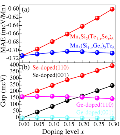
In addition, as the doping increases, the calculated band gap of the FiM state of Mn3Si2(Te1-xSex)6 smoothly increases for both the spin orientations [110] and [001] [see Fig. 10(b)]. For Mn3(Si1-xGex)2Te6, the calculated band gaps just slightly change for the two different spin orientations, at the doping levels we studied. Note that the different behavior of the calculated band gaps for the Se-doped and Ge-doped cases are also independent of [See Fig. S5(b)]. As discussed in Section III.A, the band gap of this system is mainly caused by the occupied Te and unoccupied Mn orbitals. By doping Se into the Te sites, the states near the Fermi level would be more localized, leading to a reduced bandwidth, resulting in an increased band gap, as the doping increases. However, the and states should not be seriously affected by doping Ge in the Si sites because most Si states are located at deep energies far from the Fermi level. Hence, the calculated band gap does not change much in the small doping region.
Furthermore, in the FiM state with spin orientation both along the plane and -axis, the system displays insulating behavior with an indirect band-gap characteristic of the Se-doped case. Here, we also calculated the band structure of the FiM state for the Se doping case, for both spins along and directions, as shown in Figs. 11(a-b). The calculated indirect band gaps of the FiM state of the Se doping case are about and meV for the spin lying along or along , respectively. In this case, the insulator-metal transition disappears by switching the angle between the [110] and [001] axis. This large gap in the FiM () state would greatly reduce the conductivity of the system, leading to a far more reduced colossal angular MR effect. This could qualitatively explain the strongly reduced colossal angular MR of the Sr-doping case observed at K Seo:nature .
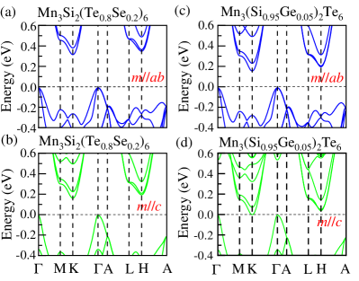
Moreover, the difference of band gaps between the two different spin orientations gradually decreases to meV in Mn3Si2(Te0.8Se0.2)6, due to the reduced SOC effect of Se. For the Ge-doping case, the calculated band gap of the FiM state slightly increases, reaching the maximum value at ( and meV for the // or //, respectively), and then decreases for the spin both lying along the plane and -axis, as the doping increases. At in the Ge-doped case, the calculated indirect band gaps are and meV for the spins along plane and -axis, respectively [see Figs. 11(c-d)]. This small gap of Mn3(Si0.95Ge0.05)2Te6 in the FiM (//) state would reduce the conductivity of the system, leading to a reduced colossal angular MR effect, compared to the undoped case. Different from the large gap of the FiM (//) state in the Sr-doping case, the reduced amplitude of the colossal angular MR effect is not too large in the Ge-doped case. This also could qualitatively explain the slightly reduced colossal angular MR effect in the Ge-doped case, at very low temperatures Seo:nature .
IV III. Conclusions
In this publication, we systematically studied the layered system Mn3Si2Te6 with alternating stacking of honeycomb and triangular layers, by combining first-principles DFT and classical MC calculations. Based on the ab initio DFT results, we found that the ferrimagnetic state is the most likely magnetic ground state, in agreement with previous neutron results. In addition, the states near the Fermi level are primarily contributed by the Te -states hybridized with the Mn -orbitals, leading to a charge transfer system. Furthermore, the spin orientations of the FiM state display different behaviors: insulating state in the plane and metallic state in the out-of-plane direction, while the energy difference between them is only about meV. In this case, the very similar energies between the FiM [110] insulating and FiM [001] metallic phases are likely responsible for the observed CMR effect in experiments. By changing the angle of the spins orientation, the calculated band gap rapidly is reduced, leading to an insulator-metal transition, which could also explain the observed colossal angular MR effect.
By mapping the DFT energy to a Heisenberg model, we obtain three magnetic exchange couplings, all of them AFM. In addition, we also constructed the magnetic phase diagram varying / and / ( was fixed to be -1), based on the classical Heisenberg model using the MC method, where three magnetic phases were obtained. Moreover, we also investigated the Se- or Ge-doping in Mn3Si2Te6. The FiM state has the lowest energy among the magnetic candidates for both cases. Due to the reduced orbital moment of Mn in the Se-doped case, the MAE slightly decreases as the doping level increases. However, for the Ge-doped case, the calculated orbital moments of Mn remain almost unchanged, as the doping level increases. Hence, the MAE of the Ge-doped case does not change in the doping level range studied here. Furthermore, the insulator-metal transition caused by the spin orientation disappears in the Se-doped case because of the strongly reduced spin-orbital coupling effect of Se, resulting in an insulating phase in the FiM [001] phase, leading to a reduced colossal angular MR. However, the band gap of the Ge-doped case does not change much for both the [110] and [001] directions, as the doping level increases. Thus, we believe our results for Mn3Si2Te6 provide guidance to experimentalists and theorists working in this system or related materials.
V Acknowledgments
The work of Y.Z., L.-F.L., A.M., and E.D. was supported by the U.S. Department of Energy, Office of Science, Basic Energy Sciences, Materials Sciences and Engineering Division.
VI APPENDIX
Here, all the magnetic orders were fully relaxed based on the LSDA+ procedure. First, the in-plane and -axis lattice constants of various magnetic orders for relaxed structures are summarized in Figs. 12(a) and (b), varying . As increases, the calculated lattice constants increases. Clearly, the eV value gives the most accurate structure, where our optimized lattice constants are , Å for the FiM spin state, close to the low-temperature experimental results (, Å Ni:prb21 . As shown in Fig. 12(c), the FiM state always has the lowest energy among all candidate configurations, in agreement with neutron experiments. Increasing , the calculated magnetic moment increases from to /Mn, for the Mn1 and Mn2 sites, respectively.
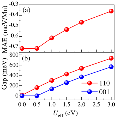
Turning on the SOC, the spin quantization axis of the FiM state still points along the plane, independently of . In addition, we also calculated the MAE (E[110]-E[001]) for the FiM state varying , as displayed in Fig. 13(a). As expected, the band gap of the FiM state increases as increases. Furthermore, the calculated band gaps are reduced by changing the spin orientation from the [110] to the [001] directions, as shown in Fig. 13(b). Increasing the values of , the total band gap continues to increase in the ground FiM () state, since increasing would increase the Mott-gap of Mn orbitals and shift the occupied Mn state to a lower energy region in this system. By switching the spin orientation of FiM to the out-plane direction (), the band gap would be reduced. The reduced values of the gap ([110]-[001]) do not change much varying because this reduced gap is driven by the SOC of the Te atom by lifting the nodal-line degeneracy, independent of the values of .
References
- (1) M. Imada, A. Fujimori, and Y. Tokura, Rev. Mod. Phys. 70, 1039 (1998).
- (2) A. Moreo, S. Yunoki, and E. Dagotto, Science 283, 2034 (1999).
- (3) E. Dagotto, Science 309, 257 (2005).
- (4) Y. Zhou, K. Kanoda, and T.-K. Ng, Rev. Mod. Phys. 89, 025003 (2017).
- (5) G. Cao, and P. Schlottmann, Rep. Prog. Phys. 81, 042502 (2018).
- (6) J. Varignon, M. Bibes, and A. Zunger, Nat. Commun. 10, 1658 (2019).
- (7) Y. Zhang, L.-F. Lin, W. Hu, A. Moreo, S. Dong, and E. Dagotto, Phys. Rev. B 102, 195117 (2020).
- (8) T. Takayama, J. Chaloupka, A. Smerald, G. Khaliullin, and H. Takagi, J. Phys. Soc. Jpn. 90, 062001 (2021).
- (9) S.-H. Do, K. Kaneko, R. Kajimoto, K. Kamazawa, M. B. Stone, J. Y. Y. Lin, S. Itoh, T. Masuda, G. D. Samolyuk, E. Dagotto, W. R. Meier, B. C. Sales, H. Miao, and A. D. Christianson, Phys. Rev. B 105, L180403 (2022).
- (10) E. Dagotto, T. Hotta, and A. Moreo, Phys. Rep. 344, 1 (2001).
- (11) Y. Tokura, Rep. Prog. Phys. 66, 797 (2006).
- (12) T. Wu, S. B. Ogale, J. E. Garrison, B. Nagaraj, A. Biswas, Z. Chen, R. L. Greene, R. Ramesh, T. Venkatesan, and A. J. Millis, Phys. Rev. Lett. 86, 5998 (2001).
- (13) T. Z. Ward, J. D. Budai, Z. Gai, J. Z. Tischler, L. Yin and J. Shen, Nature. Phys. 5, 885 (2009).
- (14) H. Lin, H. Liu, L. Lin, S. Dong, H. Chen, Y. Bai, T. Miao, Y. Yu, W. Yu, J. Tang, Y. Zhu, Y. Kou, J. Niu, Z. Cheng, J. Xiao, W. Wang, E. Dagotto, L. Yin, and J. Shen, Phys. Rev. Lett. 120, 267202 (2018).
- (15) T. Miao, L. Deng, W. Yang, J. Ni, C. Zheng, J. Etheridge, S. Wang, H. Liu, H. Lin, Y. Yu, Q. Shi, P. Cai, Y. Zhu, T. Yang, X. Zhang, X. Gao, C. Xi, M. Tian, X. Wu, H. Xiang, E. Dagotto, L. Yin, and J. Shen, Proc. Natl. Acad. Sci. USA 117, 7090 (2020).
- (16) I. A. Sergienko and E. Dagotto, Phys. Rev. B 73, 094434 (2006).
- (17) I. A. Sergienko, C. Şen, and E. Dagotto, Phys. Rev. Lett. 97, 227204 (2006).
- (18) J. v. d. Brink and D. I. Khomskii, J. Phys.: Condens. Matter 20, 434217 (2008).
- (19) S. Dong, H. Xiang, and E. Dagotto, Nat. Sci. Rev. 6, 629 (2019).
- (20) P. V. Balachandran and J. M. Rondinelli, Phys. Rev. B 88, 054101 (2013).
- (21) J. Varignon, M. N. Grisolia, D. Preziosi, P. Ghosez, and M. Bibes, Phys. Rev. B 96, 235106 (2017).
- (22) B. Pandey, Y. Zhang, N. Kaushal, R. Soni, L.-F. Lin, W.-J. Hu, G. Alvarez, and E. Dagotto, Phys. Rev. B 103, 045115 (2021).
- (23) L.-F. Lin, N. Kaushal, Y. Zhang, A. Moreo, and E. Dagotto, Phys. Rev. Matter. 5, 235106 (2021).
- (24) E. Dagotto, Rev. Mod. Phys. 66, 763 (1994).
- (25) E. Dagotto, Rev. Mod. Phys. 85, 849 (2013).
- (26) P. Dai, Rev. Mod. Phys. 87, 855 (2015).
- (27) D. Li, K. Lee, B. Y. Wang, M. Osada, S. Crossley, H. R. Lee, Y. Cui, Y. Hikita, and H. Y. Hwang, Nature 527, 624 (2019).
- (28) A. F. May, Y. Liu, S. Calder, D. S. Parker, T. Pandey, E. Cakmak, H. Cao, J. Yan, and M. A. McGuire, Phys. Rev. B 95, 174440 (2017).
- (29) G. Sala, J. Y. Y. Lin, A. M. Samarakoon, D. S. Parker, A. F. May, and M. B. Stone, Phys. Rev. B 105, 214405 (2022).
- (30) Y. Liu, Z. Hu, M. Abeykoon, E. Stavitski, K. Attenkofer, E. D. Bauer, and C. Petrovic, Phys. Rev. B 103, 245122 (2021).
- (31) Y. Ni, H. Zhao, Y. Zhang, B. Hu, I. Kimchi, and G. Cao, Phys. Rev. B 103, L161105 (2021).
- (32) J. Wang, S. Wang, X. He, Y. Zhou, C. An, M. Zhang, Y. Zhou, Y. Han, X. Chen, J. Zhou, and Z. Yang, Phys. Rev. B 106, 045106 (2022).
- (33) Y. Zhang, Y. Ni, H. Zhao, S. Hakani, F. Ye, L. DeLong, I. Kimchi and G. Cao, Nature (2022).
- (34) J. Seo, C. De, H. Ha, et al., Nature 599, 576 (2021).
- (35) F. Ye, M. Matsuda, Z. Morgan, T. Sherline, Y. Ni, H. Zhao, and G. Cao, Phys. Rev. B 106, L180402 (2022).
- (36) S. D. Mijin, A. Šolajić, J. Pešić, Y. Liu, C. Petrovic, M. Bockstedte, A. Bonanni, Z. V. Popović, and N. Lazarević, Nenad, arXiv:2209.02664v1 (2022).
- (37) G. Kresse and J. Hafner, Phys. Rev. B 47, 558 (1993).
- (38) G. Kresse and J. Furthmüller, Phys. Rev. B 54, 11169 (1996).
- (39) P. E. Blöchl, Phys. Rev. B 50, 17953 (1994).
- (40) J. P. Perdew, K. Burke, and M. Ernzerhof, Phys. Rev. Lett. 77, 3865 (1996).
- (41) S. L. Dudarev, G. A. Botton, S. Y. Savrasov, C. J. Humphreys, and A. P. Sutton, Phys. Rev. B 57, 1505 (1998).
- (42) K. Momma and F. Izumi, J. Appl. Crystallogr. 44, 1272 (2011).
- (43) See Supplemental Material at http://link.aps.org/supplemental/10.1103/PhysRevB.xx/xxxxxx. for more results.
- (44) J. P. Perdew, A. Ruzsinszky, G. I. Csonka, O. A. Vydrov, G. E. Scuseria, L. A. Constantin, X. Zhou and K. Burke, Phys. Rev. Lett. 100, 136406 (2008).
- (45) L.-F. Lin, L. Z. Wu, and S. Dong, Front. Phys. 11, 117502 (2016).
- (46) Y. Zhang, L.-F. Lin, J.-J. Zhang, X. Huang, M. An, and S. Dong, Phys. Rev. Mater. 1, 034406 (2017).
- (47) L.-F. Lin, Q.-R. Xu, Y. Zhang, J.-J. Zhang, Y.-P. Liang, and S. Dong, Phys. Rev. Materials 1, 071401(R) (2017).
- (48) Y. Zhang, L.-F. Lin, A. Moreo, S. Dong, and E. Dagotto, Phys. Rev. B 101, 144417 (2020).
- (49) M. B. Salamon and M. Jaime, Rev. Mod. Phys. 73, 583 (2001).
- (50) In addition, we also studied the effect of the exchange interaction using the LSDA++ with the Liechtenstein formulation Liechtenstein:prb . As expected, the magnetic coupling parameters do not change as discussed in the Supplemental Materials.
- (51) A. I. Liechtenstein, V. I. Anisimov, and J. Zaanen, Phys. Rev. B 52, R5467 (1995).
- (52) F. Du, L. Yang, Z. Nie, N. Wu, Y. Li, S. Luo, Y. Chen, D. Su, M. Smidman, Y. Shi, C. Cao, F. Steglich, Y. Song and H. Yuan, npj Quantum Mater. 7, 65 (2022).
- (53) L. Bellaiche and D. Vanderbilt, Phys. Rev. B 61, 7877 (2000).
- (54) N. J. Ramer and A. M. Rappe, Phys. Rev. B 62, R743(R) (2000).
- (55) Y. Zhang, L.-F. Lin, A. Moreo, G. Alvarez, and E. Dagotto Phys. Rev. B 103, L121114 (2021).