Autonomous Marker-Less Rapid Aerial Grasping
Abstract
In a future with autonomous robots, visual and spatial perception is of utmost importance for robotic systems. Particularly for aerial robotics, there are many applications where utilizing visual perception is necessary for any real-world scenarios. Robotic aerial grasping using drones promises fast pick-and-place solutions with a large increase in mobility over other robotic solutions. Utilizing Mask R-CNN scene segmentation (detectron2), we propose a vision-based system for autonomous rapid aerial grasping which does not rely on markers for object localization and does not require the appearence of the object to be previously known. Combining segmented images with spatial information from a depth camera, we generate a dense point cloud of the detected objects and perform geometry-based grasp planning to determine grasping points on the objects. In real-world experiments on a dynamically grasping aerial platform, we show that our system can replicate the performance of a motion capture system for object localization up to 94.5% of the baseline grasping success rate. With our results, we show the first use of geometry-based grasping techniques with a flying platform and aim to increase the autonomy of existing aerial manipulation platforms, bringing them further towards real-world applications in warehouses and similar environments.222https://github.com/srl-ethz/detectron-realsense
I Introduction
I-A Motivation
Over the last five years, drones have gained significant popularity as tools to observe and capture the world around us through photographs and videos both for consumers and industry alike. With the rise of soft gripping technology, drones are gaining more capabilities for physical interaction with their environments. However, these capabilities will only find use if the drones have a way of efficiently perceiving the environment around them. The capabilities of an autonomous robotic system are always going to be limited by the information the system receives. For instance, a drone which can grasp objects but has no way of locating its target objects is rather limited for any real-world autonomous use cases.
A common solution in research is to use motion capture systems as a quick and precise solution to provide localization data. However, it is infeasible for industrial use to attach markers to every object that a robot should grasp. Solutions for object localization using fiducial markers like ArUco markers [1] exhibit the same problem. Vision-based localization solutions that solely rely on monocular vision also do not have the capability of perceiving depth and cannot provide us with sufficient spatial information for rapid grasp planning.
To solve these challenges, we present a vision-based, marker-less system for object localization and grasp planning. Using a stereoscopic camera (Intel RealSense D455 [2]) for color and depth information, Mask R-CNN-based [3] scene segmentation (detectron2 [4]), and efficient point cloud processing for grasp planning (Open3D [5]), our system gives robots the ability to perform marker-less autonomous grasping. The use of mobile platforms, especially when in air, is accompanied by major challenges such as a substantial increase in tracking uncertainty, making it difficult to execute precise grasps. Furthermore, in the case of mobile manipulation, target objects can be much further away compared to static manipulation scenarios, which reduces the pixel size of the objects in the image and therefore increases the importance of precise scene segmentation.
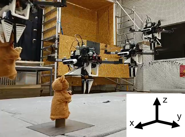
We use RAPTOR [6] as a platform for deploying our system. RAPTOR combines a quadcopter with a soft Fin Ray ® gripper which passively adapts to the shape of the objects that are being grasped. It is a platform that is capable of dynamically picking up different objects at high speeds. Using RAPTOR as a platform also allows us to compare our grasping performance against a known baseline grasping performance using a motion capture system for object localization.
Our solution allows a mobile aerial platform to quickly and autonomously detect possible grasping targets (without any markers attached to them), localize them, and execute a grasp. Using Mask R-CNN [4] image segmentation, we can generate dense point clouds of novel objects.
As opposed to previously used learning-based methods, our approach allows for highly precise object segmentation, even at larger distances (for example: bottles with 10 pixels width, about away from the camera). This capability presents a key step in bringing mobile aerial robotic platforms, such as RAPTOR, towards autonomous grasping and manipulation and eventually enable real-world applications.
Furthermore, we expand on the detection and grasp planning scheme that is typically shown in previous works with details such as a detailed runtime analysis and quantify the localization accuracy and grasping performance of our system. Finally, we also explicitly decouple our segmentation and grasp planning pipeline from the motion planning of the system. Thus, it will be easy to port the vision system to other mobile manipulation platforms for usage beyond the RAPTOR platform.
I-B Related Work
I-B1 Aerial Grasping and Vision-based Control of Quadcopters
Control using visual information is generally referred to as visual servoing. Position-based visual servoing for quadcopters uses visual information to estimate a kinematic error in Cartesian space. Image-based visual servoing relies exclusively on estimating a control error in the two-dimensional image space. So-called hybrid approaches combine both visual servoing approaches into one control strategy.
Multiple works on aerial grasping exist that use marker-based target designations. Typically, they use reflective balls mounted on the object for localization using external infrared cameras (motion capture systems) or fiducial markers (ArUco markers [1], AprilTags [7]). Using traditional rigid manipulators, Lippiello et al. [8] and Buonocore et al. [9] have shown a marker-based hybrid visual servoing approach for manipulation. More recently, rapid aerial grasping using soft gripping mechanisms has been shown using a motion capture system for estimating the pose of the target object by Fishman et al. [10, 11] and Appius et al. [6].
Marker-less methods for vision-based control of quadcopters have the advantage of not requiring target objects to be manually outfitted with markers. Luo et al. [12] perform feature matching for detection with a monocular camera while Lin et al. [13] propose learning-based approaches for object detection and grasp planning. Ramón-Soria et al. [14] show a marker-less aerial grasping approach with a stereoscopic camera. They use a CNN (convolutional neural network) for detecting possible target regions that contain the known target object and extract the pose of the target object by applying the iterative closest points (ICP) algorithm [15]. Ramón-Soria et al. [16] also show aerial grasping using traditional visual features like SIFT [17] or FAST [18] for detecting objects. A similar problem to grasping is perching: Thomas et al. [19] have shown a control approach for perching on known cylindrical objects using visual-servoing. Seo et al. [20] show aerial grasping of similar cylindrical objects, making use of RANSAC (Random Sample Consensus) to detect the target cylinder and then use stochastic model predictive control for executing grasps.
In contrast to existing works, we use use a more powerful detection approach that is able to generalize to many different objects of unknown shapes. Using a learning-based method lifts requirements like having markers on the target objects or needing prior information about the shape or dimensions of the target objects as is the case for most feature-based methods. Mask R-CNN as segmentation method allows us to significantly expand the workspace of the robot compared to previous works, which rely on being within close range of the target object. Not only is this crucial for real-world applications, but it also allows us to make grasping maneuvers more dynamic compared to the marker-less state of the art platforms.
I-B2 Vision-based Grasping With Statically Mounted Manipulators
Previous works show a number of approaches for grasp planning with statically mounted manipulation platforms such as robotic arms that remain at a fixed position in their workspace. These approaches are mainly constructed around using vision to extract a point cloud of the object. One of the proven strategies is geometry-based grasp planning [21, 22]. While in recent years learning-based approaches [23, 24] for grasp planning have shown to be capable of generating precise grasps, they require comprehensive data sets. Methods using reinforcement learning [25] have also been explored, however, they have a high complexity in implementation and their generalization remains a challenging task.
While robotic arms and similar platforms have been used with great success for object manipulation, their inherently limited workspace restricts their practical applications. With our approach, which is based on extracting dense point clouds of objects, we lay the groundwork for implementing these successful grasp planning algorithms on highly mobile platforms such as RAPTOR.
I-C Contributions
Our proposed vision system uses Mask R-CNN for powerful learning-based instance segmentation and extracting point clouds of target objects. Combining learning-based target point cloud extraction with geometry-based grasp planning, our approach allows for marker-less rapid aerial grasping without the need for artificial markers on the target objects. Due to the use of Mask R-CNN, our approach can precisely segment objects even at further distances which expands the workspace of the aerial platform and allows for rapid approaches towards the target that do not rely on slow closed-loop visual servoing during the approach.
Validating our system on the RAPTOR [6] platform, the currently fastest quadcopter for aerial manipulation, we provide insights into the design decisions for the system and extensive performance metrics compared to a motion capture baseline. Finally, we outline future work to increase the abilities of vision-based aerial manipulation platforms.
II Object Segmentation and Grasp Planning
II-A Creating the Object Point Cloud
There are two major steps required for acquiring point clouds of target objects: First, we use an RGB image of the object to detect it and use instance segmentation to get a segmentation mask. Second, we use the segmentation mask to filter out points in the RGB-D image and keep a dense point cloud of the target object.
II-A1 Instance Segmentation
We use Mask R-CNN (detectron2 [4]) for segmenting the RGB images from the camera. R-CNN-based architectures [26, 4] have proven themselves to handle well small objects in the frame compared to more lightweight architectures [27, 28] that also feature instance segmentation capabilities. Being able to detect and segment objects precisely from further distances is crucial to expand the workspace of the robot and rely less on human operators to guide it within close proximity of target objects. With a detection method like YOLOv5 [29], we were able to reliably detect small objects like bottles at distances of around whereas using Mask R-CNN allowed us to expand the distances up to .
While it is also possible to use simpler object detection methods that generate a rough bounding box estimate for the object and then use ICP for to refine the estimate [14] or graph cut segmentation, an all-in-one detection and segmentation approach simplifies training and can make use of running entirely on a GPU (Graphics Processing Unit).
II-A2 From Segmentation to Point Cloud
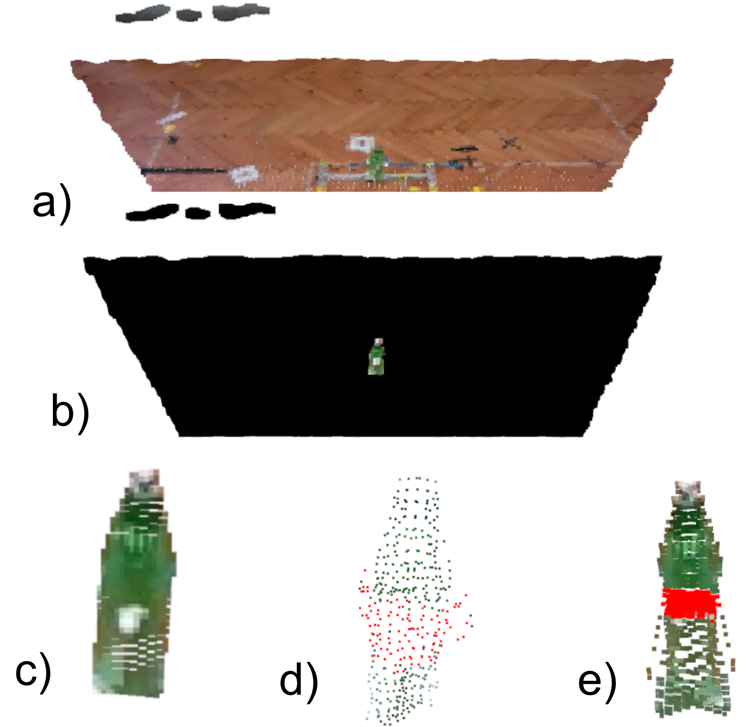
Once a target object is segmented from the scene, we apply the segmentation mask to the RGB image. We then combine the masked RGB image with its corresponding depth image to create a cropped point cloud of the scene. Next, we remove all points in the point cloud which are black due to having been masked out in the previous step. This preprocessing yields a point cloud of the surface of the object that is visible to the camera. Finally, we apply radius outlier removal (as implemented in Open3D [5]) to correct for any possible outliers that the mask might have accidentally included as part of the object and apply voxel downsampling to reduce the computational load for further computations. A visual representation of this process is given in Figure 2.
II-B Computing a Grasp
We choose a relatively simple geometry-based strategy for selecting grasping points which is inspired by Zapata-Impata et al. [21] who previously implemented their algorithm on a static platform using a robotic arm. Bringing this algorithm to a flying platform, we make the following assumptions that are necessary for stable flight with the quadcopter after grasping the object: the object fits into the gripper on the drone, it weighs less than and is approximately axially symmetric.
Our adapted algorithm can be summarized into four major aspects:
-
1.
Estimate the centroid of the point cloud and determine its pose.
-
2.
Duplicate the point cloud and rotate it around the axis with the largest extent, making use of the assumption about symmetry to estimate front and back of the object.
-
3.
Determine the new centroid and the new pose of the combined point cloud.
-
4.
Determine a set of candidate points by taking the intersection of the point cloud and a cutting plane that goes through the estimated centroid and is normal to the axis with the largest extent. These candidates mark the possible contact spots for our gripper on the front and the back.
III Mobile Vision Architecture

III-A Compute Platform
The use of mobile compute platforms with powerful GPUs on drones has been explored before [30] and has been shown to be a viable alternative to offboard computation. However, it comes at the cost of significantly increased weight and power consumption onboard the drone while still not living up to the processing times possible by performing the computations offboard. As detectron2 runs at very slow speeds on these mobile compute platforms (around 10 seconds per frame on Nvidia Jetson Nano), we choose to use run the computations on a more powerful offboard desktop PC with an Nvidia RTX 3070 GPU to accelerate segmentation runtimes. Onboard the drone, an Nvidia Jetson Nano [31] is used to capture, compress and send the RGB and depth frames from the Intel RealSense D455 [2] camera.
Additionally, we have also equipped the Nvidia Jetson Nano with an Intel AC8265 wireless networking card which is much faster than the wireless networking hardware on simpler single-board-computers like a Raspberry Pi 4. The two computers are connected over an industrial-grade wireless router with 1 Gbps bandwidth.
III-B Data Pipeline
We send color and depth frames to the offboard computer over the local network, do the most intensive computations there and then forward the result to the RAPTOR system over the local network as shown in Figure 3. Not only does this architecture allow us to use the vision system as a drop-in replacement for the previously used motion capture system, but its modular nature also allows the vision system to be quickly integrated into other platforms. Additionally, the system can also be deployed on an onboard computer with ease should sufficiently powerful compute platforms be available.
III-B1 Dataflow
We start with the camera image publisher running onboard the drone on a Nvidia Jetson Nano which compresses both RGB and depth frames from the Intel RealSense D455 camera and sends them to the offboard computer. On the offboard computer, we run scene segmentation with detectron2 [4] and object localization and grasp planning using Open3D [5]. The obtained target coordinates are transformed into the global motion capture frame, in which the trajectory planning for RAPTOR happens. To transform the coordinates, we receive the pose of the drone from a bridge process. In turn, the bridge process receives the transformed target coordinates which it then forwards to the trajectory generator. From there, it will be sent to the flight controller of the drone (Pixhawk 4 [32]) using MAVlink [33], which then handles all lower levels of control to fly the drone to the target position.
III-B2 Synchronisation of Processes
We use a request-reply communication pattern within ZeroMQ, ensuring synchronization of the different processes. In case one process fails, this failure will interrupt the request-reply scheme and the other processes will not keep operating on old or invalid data as it would be the case with the Fast DDS publisher-subscriber model.
III-B3 Transport and Serialization
The RAPTOR system is currently not using ROS (Robot Operating System) [34] but rather a custom Fast DDS wrapper to reduce computational overhead by a factor of up to 1.5 [35]. To enable interoperability with other languages than C++, we extended the system building up on ZeroMQ (ZMQ) [36] and Protobuf [37]. This extends the system to be used with all other major programming languages (Python, Rust, …) while maintaining support for ROS-like messages and low computational overhead. As visible in 3, the vision system uses ZMQ (combined with Protobuf messages) to connect to the RAPTOR system while the RAPTOR system relies on Fast DDS and MAVLink to enable communication in between processes.
III-C Image Streaming and Compression
Real-time image streaming is one of the main challenges related to offboard computing. We cannot use lossy compression for the depth frames as that would incur large losses in the localization accuracy. For the RGB frames, however, we can use lossy compression to minimize the transmission size in a computationally efficient way.
III-C1 Hybrid compression scheme
Accordingly, we make use of a hybrid compression scheme (Figure 5) similar to work presented by Coatsworth et al. [38]. We access one stream of RGB frames and one stream of Z16 depth frames from the Intel RealSense D455 [2] camera, both with a resolution of 640 by 480 pixels. Then, we compress the RGB frame using lossy JPG compression and the depth frame using lossless PNG compression. For JPG compression, we use a quality of 95 whereas for PNG compression, we use a compression factor of 2 (compression algorithms from OpenCV [39] are used).

III-C2 Latency
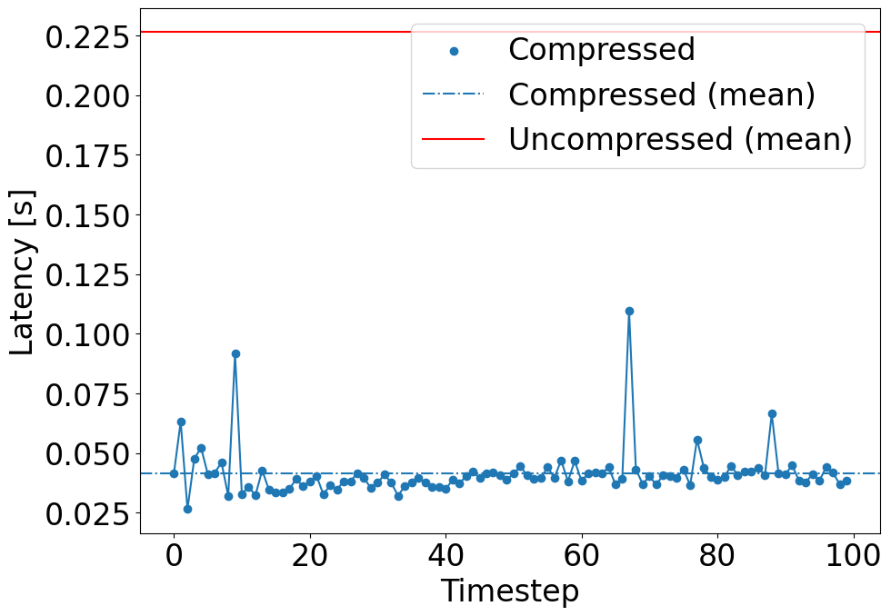
In total, the time to compress the frames and send them to the offboard computer is much lower than directly using image segmentation on the onboard computer given the currently suitable onboard computers. Our use of offboard computing is motivated by the total time needed to process one frame; however, in more latency-critical applications or for outdoor deployment, using onboard segmentation with reduced framerates may be necessary. For possible future work exploring outdoor scenarios, we can easily port the system to a single onboard computer to take advantage of lower latencies.
III-C3 Compression Parameters
To find the compression parameters, we used a runtime analysis of the system. The rate at which the onboard computer sends images should at most be the rate at which the offboard computer can process them. Thus, we choose the highest compression parameters that allow the runtime to be less than that of the main loop. Runtimes are listed in Section IV-A1.
IV Results and Discussion
IV-A Performance Analysis
In the following, we analyze the system performance of the vision system. There are two relevant components: the times required for processing and the times required for sending data in between processes.
IV-A1 Process Timings
The camera image publisher running on the Jetson Nano takes on average to get, compress, and send a pair of RGB and depth frames. Image decompression, scene segmentation and grasp planning on the offboard computer takes approximately on average, of which the largest part can be attributed to image segmentation () and point cloud processing (). The RAPTOR processes for trajectory generation and data transfer run at a speed of per iteration.
IV-A2 Networking Latency
All offboard processes run on the same computer and the time messages spend in transport is on the order of nanoseconds. However, there is considerable networking latency when sending the image frames from the Jetson Nano on the drone to the offboard computer. For transport, the TCP implementation of ZMQ is used. A showcase of the transit times of images is given in Figure 4.
IV-B Localization Performance
In the following, we give an overview of the localization performance of our system compared to the ground truth using motion capture. We first describe our evaluation methodology and then the test results.
IV-B1 Evaluation Methodology
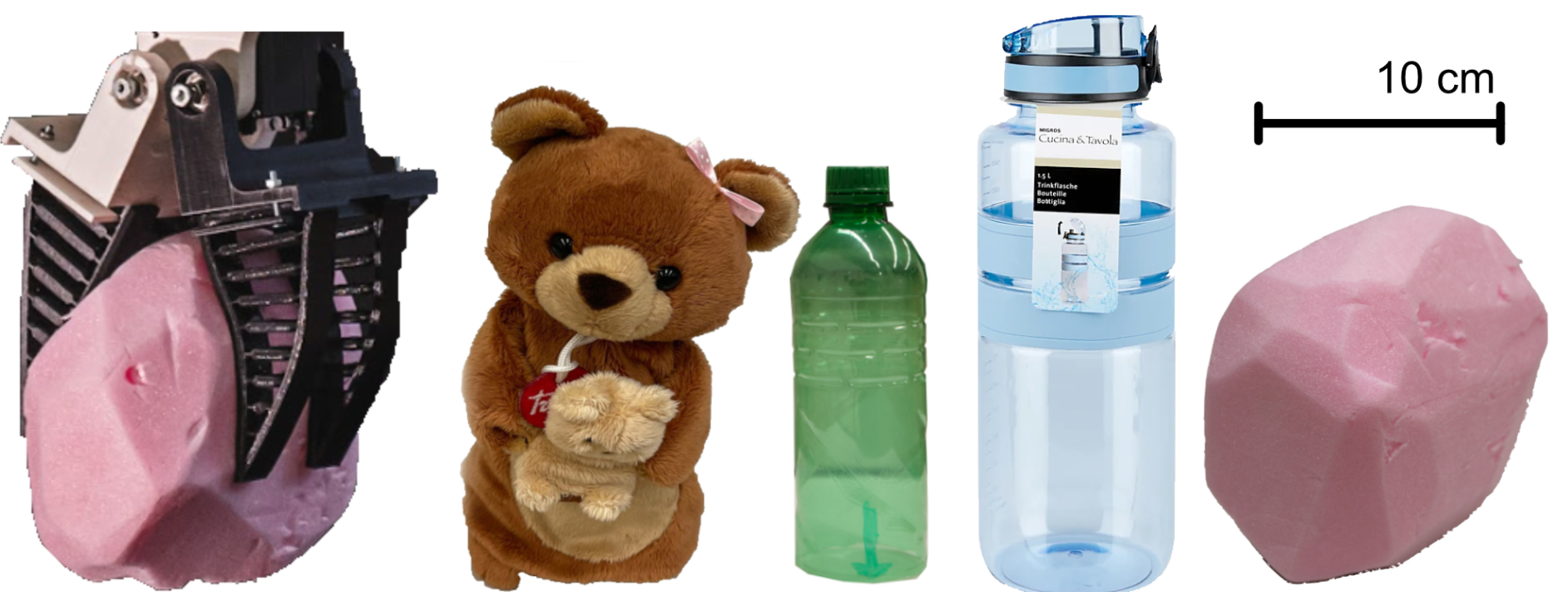
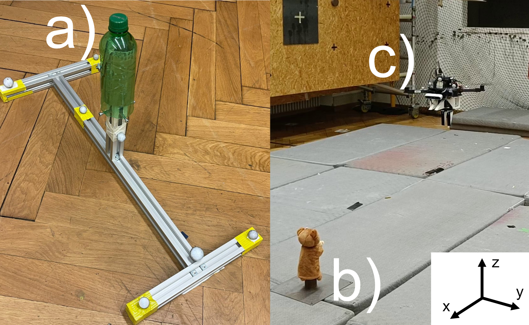
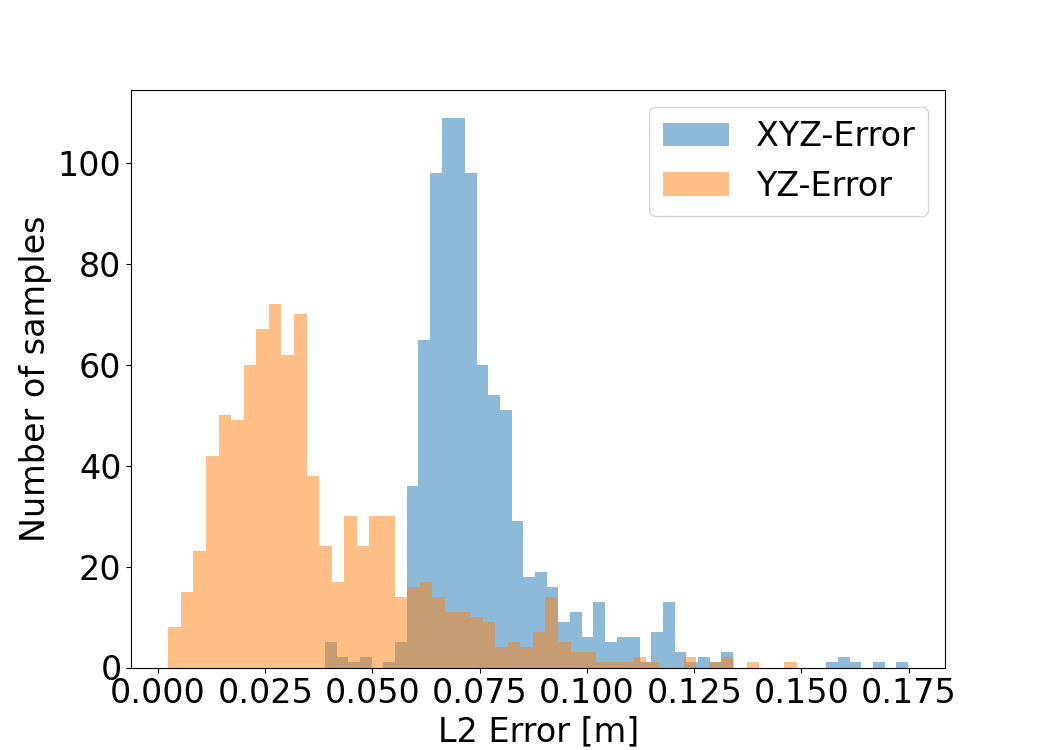
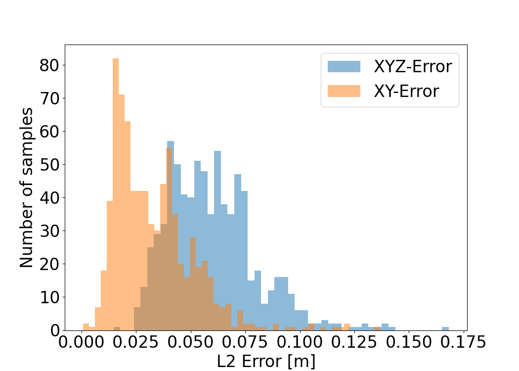
We have conducted localization tests using a teddy bear and a PET bottle as test objects (shown in Figure 6). Both objects fulfil all criteria of being grasped by our system. Furthermore, it is noted that the bottle is perfectly symmetrical and the teddy bear is slightly asymmetrical towards its camera-facing side. Both objects were mounted on a stand (see Figure 7), which was equipped with motion capture markers. The center of the frame of the stand was calibrated to be exactly on top of the aluminum extrusion that provides the mounting point for the objects. The objects were placed on the stand shown in Figure 7 to provide the best approximation for their centroids.
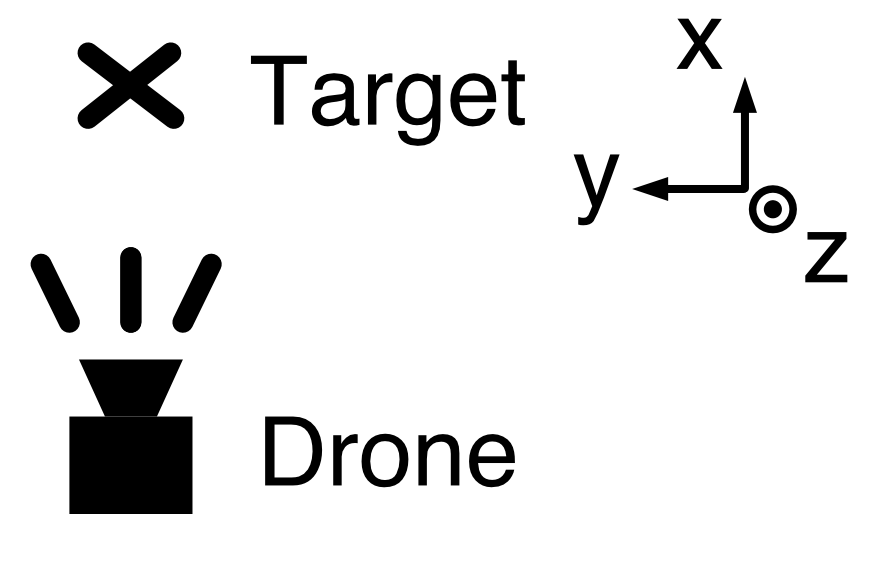
Localization performance is evaluated by flying the drone across the room at set distances from the target object. The drone flies across the room in regular increments, hovers for a brief amount of time and then flies to the next point, thus giving us insight on the performance while the drone was both moving and hovering. We compare the position of the target as computed by the vision system to the one provided by the motion capture system and compute the distance in between the positions as error metric.
IV-B2 Localization Results
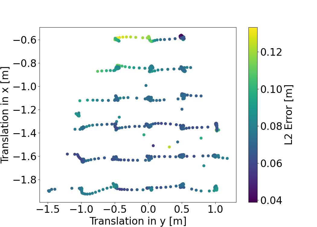
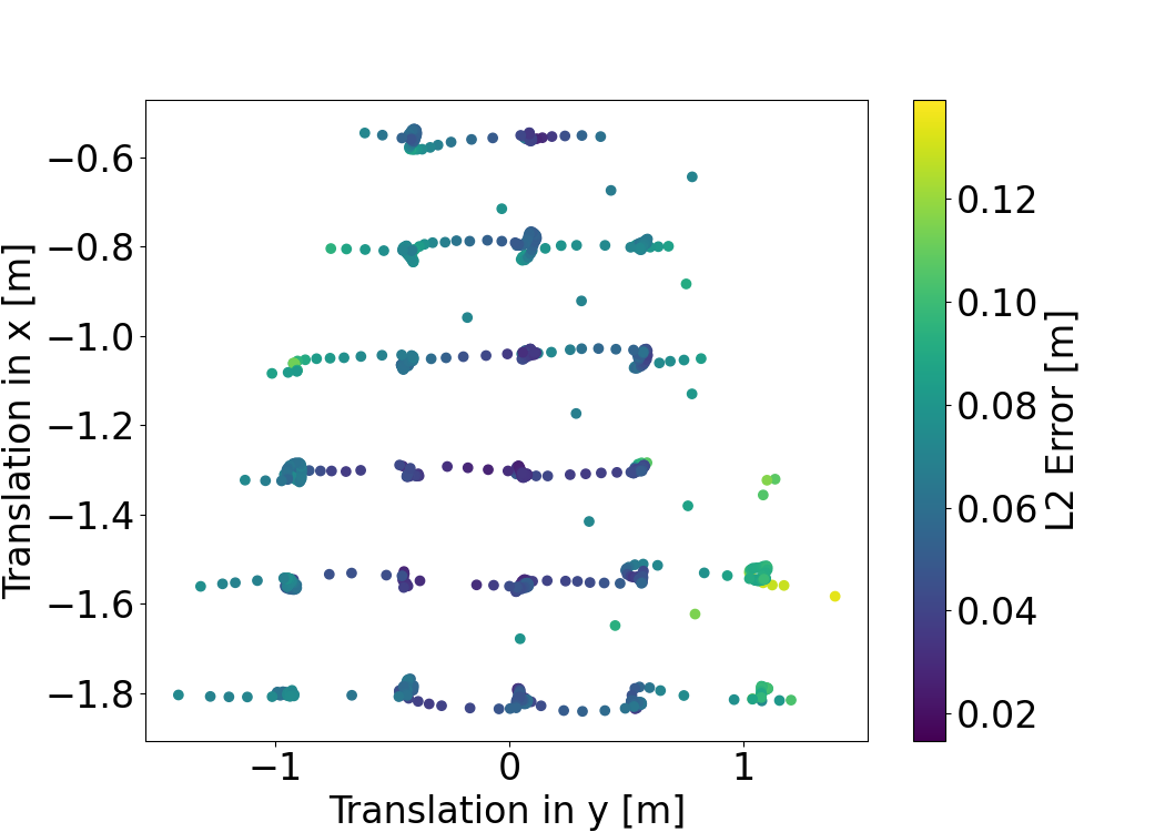
We show figures of our localization test results for the bottle and the bear in Figure 9 and Figure 10. Displaying the spatial distribution of the error, we can observe that the error increases as the object is at the edges of the camera frame. It is also visible that the error slightly increases in between the hovering points of the drone, which can likely be attributed to larger mismatch in the image timestamp and the pose of the drone when it is dynamically moving around.
IV-C Validation with Grasping Tests
Finally, we validate the grasping performance of our system. By comparing the grasping success rates when using the motion capture system for object localization and using our vision-based system for object localization, we can establish the percentage of localization errors that fall inside an acceptable range for a successful grasp.
We first explain the choice of test objects, then introduce our evaluation methodology, and finally present the test results.
IV-C1 Test Objects
We conducted the grasping test with the same teddy bear from the error analysis shown in Section IV-B and a slightly larger and heavier bottle shown in Figure 6. The choice falls on these objects since any objects that are to be grasped have to be in the COCO (Common Objects in Context) dataset, they have to fit in the gripper, and their weight has to be below 500 grams to be suitable for lifting by the drone. Furthermore, while we also tried other objects like a handbag, they were prone to be either easily blown away by the wind generated by the propellers of the drone or easily deformed by the wind. We refer to Appius et al. [6] for a showcase of the grasping abilities of RAPTOR with a wider variety of objects.
IV-C2 Evaluation Methodology
We placed both objects on top of a weight on a metal plate (shown in Figure 7) without any markers attached. This setup ensured a stable pose of both of our objects even with the drone flying close by. The stand was placed in a position where the camera would pick up on the teddy bear - about offset in x-direction and offset in y-direction. The drone executed the following mission plan:
-
1.
Fly to the center of the room and get a view of the object.
-
2.
Hover for 5 seconds and gather a first grasp estimate for the target object.
-
3.
Reposition to execute the swooping maneuver for the grasp in a straight line.
-
4.
Execute the swoop and grasp the object, then drop the object and land again.
We only stopped the drone to exchange the battery, otherwise, the testing circumstances remained equal for all tests. For each object, we completed a total of 36 grasping attempts.
IV-C3 Grasping Tests Results
For the teddy bear, we saw a success in 32 out of the 36 attempts, yielding a success rate of 89%. This success rate is a slightly worse performance compared to the baseline. The RAPTOR system as baseline previously used a marker-based stationary motion capture implementation on a similarly sized styrofoam object (shown in Figure 6) (100% grasping efficacy over 36 attempts).
Similarly, we saw for the bottle as test object 23 out of the 36 successful grasp attempts. This success rate of 64% slightly outperforms the motion capture implementation (61% over 36 attempts). Note that the new bottle used was about 2 centimeters larger in diameter than the bottle used in the localization experiments (as shown in Figure 6). We conclude that we do not have a significant loss in performance compared to a motion capture implementation when grasping objects while completely eliminating the necessity to equip the objects with markers.
If we define a localization sample from the vision system as having a relative acceptable error as being within a range small enough such that the resulting grasping efficacy compared to the motion capture system does not decrease, we can also make the following statements: for the teddy bear, 89% of localization samples with the vision system were in an acceptable range of the localization error whereas for the bottle, 100% of samples had an acceptable error. Results are shown in Table I. We relate the success rate of our vision-based approach to the success using the baseline.
| Object | Vision (ours) | Motion Capture (baseline) | Relative Acceptable Error Rate |
|---|---|---|---|
| Teddy Bear | 89% | 100% | 89% |
| PET Bottle | 64% | 61% | 100% |
The results indicate the potential of our marker-less vision-based system as an alternative for the previously used marker-based localization systems. In combination with vision-based localization techniques [40, 41] that can be deployed on quadcopters, the drone could be used outside a motion capture space.
V Conclusion
We have demonstrated our vision-based system for real-time scene segmentation and grasp planning and its capabilities as a replacement for motion-capture-based target localization solutions. Our learning-based system eliminates the need for objects to have any markers on them or be of distinctive previously known shapes. We have shown that our system can precisely localize objects for grasping and have validated the performance in real-world grasping tests with different objects on a state-of-the-art platform for aerial grasping, showing that there is nearly no loss in grasping success compared to a motion capture baseline and demonstrating a successful transfer of geometric grasp planning to an aerial platform. We detailed our system architecture including how we synchronized processes running at different speeds and deployed them on the RAPTOR platform. This work shows how we achieved real-time vision-based target object localization and grasping and serves as a foundation for future work that will extend our system’s capabilities and use case scenarios.
For future work, pushing the boundaries of the current system will be the focus of research efforts to come. Particularly, dynamic grasping in unstructured outdoor environments using visual-inertial odometry for self-localization and the ability to grasp larger, strongly asymmetric objects are the open challenges we see as most important. For enhanced grasping abilities, generating an estimate of the full three-dimensional point cloud of the object by learning-based methods could improve the grasping performance and allow more extensive grasp planning. Solving these challenges will be an important step towards giving robots a true understanding of the shape of objects and how to interact with these objects in any kind of environment. Interaction based on vision is something humans and animals have mastered long ago; giving robots a similar perception of space and objects through learning will be a major achievement for any kind of autonomously acting robotic systems.
References
- [1] S. Garrido-Jurado, R. Muñoz-Salinas, F. J. Madrid-Cuevas, and M. J. Marín-Jiménez, “Automatic generation and detection of highly reliable fiducial markers under occlusion,” Pattern Recognit., vol. 47, pp. 2280–2292, 2014.
- [2] “Intel realsense d455,” accessed: 2022-09-15. [Online]. Available: https://web.archive.org/*/https://www.intelrealsense.com/depth-camera-d455
- [3] K. He, G. Gkioxari, P. Dollár, and R. Girshick, “Mask r-cnn,” in 2017 IEEE International Conference on Computer Vision (ICCV), 2017, pp. 2980–2988.
- [4] Y. Wu, A. Kirillov, F. Massa, W.-Y. Lo, and R. Girshick, “Detectron2,” https://github.com/facebookresearch/detectron2, 2019.
- [5] Q.-Y. Zhou, J. Park, and V. Koltun, “Open3D: A modern library for 3D data processing,” arXiv:1801.09847, 2018.
- [6] A. Appius, E. Bauer, M. Blochlinger, A. Kalra, R. Oberson, A. Raayatsanati, P. Strauch, S. Suresh, M. von Salis, and R. K. Katzschmann, “Raptor: Rapid aerial pickup and transport of objects by robots,” ArXiv, vol. abs/2203.03018, 2022.
- [7] E. Olson, “Apriltag: A robust and flexible visual fiducial system,” 2011 IEEE International Conference on Robotics and Automation, pp. 3400–3407, 2011.
- [8] V. Lippiello, J. Cacace, A. Santamaria-Navarro, J. Andrade-Cetto, M. A. Trujillo, Y. Rodríguez, and A. Viguria, “Hybrid visual servoing with hierarchical task composition for aerial manipulation,” IEEE Robotics and Automation Letters, vol. 1, pp. 259–266, 2016.
- [9] L. R. Buonocore, J. Cacace, and V. Lippiello, “Hybrid visual servoing for aerial grasping with hierarchical task-priority control,” 2015 23rd Mediterranean Conference on Control and Automation (MED), pp. 617–623, 2015.
- [10] J. Fishman and L. Carlone, “Control and trajectory optimization for soft aerial manipulation,” 2021 IEEE Aerospace Conference (50100), pp. 1–17, 2021.
- [11] J. Fishman, S. Ubellacker, N. Hughes, and L. Carlone, “Dynamic grasping with a ”soft” drone: From theory to practice,” 2021 IEEE/RSJ International Conference on Intelligent Robots and Systems (IROS), pp. 4214–4221, 2021.
- [12] B. Luo, H. Chen, F. Quan, S. Zhang, and Y. hui Liu, “Natural feature-based visual servoing for grasping target with an aerial manipulator,” Journal of Bionic Engineering, vol. 17, pp. 215–228, 2020.
- [13] L. Lin, Y. Yang, H. Cheng, and X. Chen, “Autonomous vision-based aerial grasping for rotorcraft unmanned aerial vehicles,” Sensors (Basel, Switzerland), vol. 19, 2019.
- [14] P. Ramón-Soria, B. C. Arrue, and A. Ollero, “Grasp planning and visual servoing for an outdoors aerial dual manipulator,” Engineering, vol. 6, pp. 77–88, 2020.
- [15] P. J. Besl and N. D. McKay, “A method for registration of 3-d shapes,” IEEE Trans. Pattern Anal. Mach. Intell., vol. 14, pp. 239–256, 1992.
- [16] P. R. Soria, B. C. Arrue, and A. Ollero, “Detection, location and grasping objects using a stereo sensor on uav in outdoor environments,” Sensors (Basel, Switzerland), vol. 17, 2017.
- [17] G. LoweDavid, “Distinctive image features from scale-invariant keypoints,” International Journal of Computer Vision, 2004.
- [18] E. Rosten, R. B. Porter, and T. Drummond, “Faster and better: A machine learning approach to corner detection,” IEEE Transactions on Pattern Analysis and Machine Intelligence, vol. 32, pp. 105–119, 2008.
- [19] J. R. Thomas, G. Loianno, K. Daniilidis, and V. R. Kumar, “Visual servoing of quadrotors for perching by hanging from cylindrical objects,” IEEE Robotics and Automation Letters, vol. 1, pp. 57–64, 2016.
- [20] H. Seo, S. Kim, and H. J. Kim, “Aerial grasping of cylindrical object using visual servoing based on stochastic model predictive control,” 2017 IEEE International Conference on Robotics and Automation (ICRA), pp. 6362–6368, 2017.
- [21] B. S. Zapata-Impata, P. Gil, J. Pomares, and F. Torres, “Fast geometry-based computation of grasping points on three-dimensional point clouds,” International Journal of Advanced Robotic Systems, vol. 16, 2019.
- [22] R. Haschke, G. Walck, and H. J. Ritter, “Geometry-based grasping pipeline for bi-modal pick and place,” 2021 IEEE/RSJ International Conference on Intelligent Robots and Systems (IROS), pp. 4002–4008, 2021.
- [23] Y. Jiang, S. Moseson, and A. Saxena, “Efficient grasping from rgbd images: Learning using a new rectangle representation,” 2011 IEEE International Conference on Robotics and Automation, pp. 3304–3311, 2011.
- [24] A. Mousavian, C. Eppner, and D. Fox, “6-dof graspnet: Variational grasp generation for object manipulation,” 2019 IEEE/CVF International Conference on Computer Vision (ICCV), pp. 2901–2910, 2019.
- [25] S. Levine, C. Finn, T. Darrell, and P. Abbeel, “End-to-end training of deep visuomotor policies,” ArXiv, vol. abs/1504.00702, 2016.
- [26] K. He, G. Gkioxari, P. Dollár, and R. B. Girshick, “Mask r-cnn,” IEEE Transactions on Pattern Analysis and Machine Intelligence, vol. 42, pp. 386–397, 2017.
- [27] D. Bolya, C. Zhou, F. Xiao, and Y. J. Lee, “Yolact: Real-time instance segmentation,” 2019 IEEE/CVF International Conference on Computer Vision (ICCV), pp. 9156–9165, 2019.
- [28] C.-Y. Wang, A. Bochkovskiy, and H.-Y. M. Liao, “Yolov7: Trainable bag-of-freebies sets new state-of-the-art for real-time object detectors,” ArXiv, vol. abs/2207.02696, 2022.
- [29] G. Jocher, “YOLOv5 by Ultralytics,” 5 2020. [Online]. Available: https://github.com/ultralytics/yolov5
- [30] P. Foehn, E. Kaufmann, A. Romero, R. Pěnička, S. Sun, L. Bauersfeld, T. M. Laengle, G. Cioffi, Y. Song, A. Loquercio, and D. Scaramuzza, “Agilicious: Open-source and open-hardware agile quadrotor for vision-based flight,” Science Robotics, vol. 7, 2022.
- [31] “Nvidia jetson nano,” accessed: 2022-09-15. [Online]. Available: https://web.archive.org/*/https://www.nvidia.com/en-us/autonomous-machines/embedded-systems/jetson-nano/
- [32] “Pixhawk,” accessed: 2022-09-15. [Online]. Available: https://web.archive.org/*/https://pixhawk.org/
- [33] “Mavlink,” accessed: 2022-09-15. [Online]. Available: https://web.archive.org/*/https://mavlink.io/
- [34] S. Macenski, T. Foote, B. P. Gerkey, C. Lalancette, and W. Woodall, “Robot operating system 2: Design, architecture, and uses in the wild,” Science Robotics, vol. 7, 2022.
- [35] T. Kronauer, J. Pohlmann, M. Matthé, T. Smejkal, and G. P. Fettweis, “Latency overhead of ros2 for modular time-critical systems,” ArXiv, vol. abs/2101.02074, 2021.
- [36] “Zeromq,” accessed: 2022-09-15. [Online]. Available: https://github.com/zeromq/
- [37] “Protobuf,” accessed: 2022-09-15. [Online]. Available: https://github.com/protocolbuffers/protobuf
- [38] M. Coatsworth, J. Tran, and A. Ferworn, “A hybrid lossless and lossy compression scheme for streaming rgb-d data in real time,” 2014 IEEE International Symposium on Safety, Security, and Rescue Robotics (2014), pp. 1–6, 2014.
- [39] G. Bradski, “The OpenCV Library,” Dr. Dobb’s Journal of Software Tools, 2000.
- [40] C. Forster, Z. Zhang, M. Gassner, M. Werlberger, and D. Scaramuzza, “Svo: Semidirect visual odometry for monocular and multicamera systems,” IEEE Transactions on Robotics, vol. 33, no. 2, pp. 249–265, 2017.
- [41] R. Mur-Artal, J. M. M. Montiel, and J. D. Tardós, “Orb-slam: A versatile and accurate monocular slam system,” IEEE Transactions on Robotics, vol. 31, pp. 1147–1163, 2015.