Magneto-optical trapping in a near-surface borehole
Abstract
Borehole gravity sensing can be used in a number of applications to measure features around a well including rock-type change mapping and determination of reservoir porosity. Quantum technology gravity sensors based on atom interferometry have the ability to offer increased survey speeds and reduced need for calibration. While surface sensors have been demonstrated in real world environments, significant improvements in robustness and reductions to radial size, weight, and power consumption are required for such devices to be deployed in boreholes. To realise the first step towards the deployment of cold atom-based sensors down boreholes, we demonstrate a borehole-deployable magneto-optical trap, the core package of many cold atom-based systems. The enclosure containing the magneto-optical trap itself had an outer radius of () mm at its widest point and a length of () mm. This system was used to generate atom clouds at 1 m intervals in a 14 cm wide, 50 m deep borehole, to simulate an in-borehole gravity surveys are performed. During the survey the system generated on average clouds of (3.0 87Rb atoms with the standard deviation in atom number across the survey observed to be as low as .
1 Introduction
Gravity surveys are used to detect features through their density contrasts, and have an advantage over alternative techniques in that gravity is not attenuated by the intervening medium, such as borehole casing. In comparison with techniques such as ground penetrating radar or nuclear logging, this can allow for the detection of features at greater distances [1]. Additionally gravity sensing avoids the use of radioactive isotopes [2] mitigating security and health concerns. These benefits have led to gravity surveys being used in a number of environments to detect features of interest [3], including below the surface in boreholes. Borehole gravity sensing is used for a number of applications, including: remote sensing of gas and oil zones behind casing [4]; vertical density profiling for gravity map interpretation and for seismic modelling and analysis [5]; detection of geologic structures [6, 7]; determination of reservoir porosity for reserve estimates [8]; monitoring of reservoir fluid conditions for production evaluation, and rock-type change mapping [9, 10] for groundwater and engineering studies; Carbon Capture and Storage (CCS) monitoring [11, 12]; as well as tests of fundamental physics [13, 14].
Despite numerous applications for borehole gravity sensing, a major drawback is measurement time when compared to other remote sensing techniques [15]. This is primarily due to the need to average out micro-seismic vibrations and calibrate for the inherent drift in existing sensors, via repeat measurements of the same point between sets of measurements. This limits its widespread use as a measurement technique. Quantum technology gravity and gravity gradient sensors based on atom interferometry [16, 17] have the potential to overcome these issues [18]. Moreover, gravity gradient sensors have the additional benefit of negating issues arising from micro-seismic noise [19].
Quantum technology based on atom interferometry has proven to be a powerful method for precision gravity sensing [17, 18, 20, 21], with sensitivities of 4.2 ng/ having been achieved in existing sensors [22]. Within laboratories, atom interferometry has enabled precise measurements of the equivalence principle [23], the fine-structure constant [24, 25], and the gravitational constant [26]. The demonstrated performance of laboratory systems and their inherent low drift has resulted in the development of a number of transportable atom interferometry systems targeting multiple applications and operational conditions [18, 27, 28, 29, 30, 31, 32, 19, 33, 34, 35].
Before atom-interferometry based-gravity sensors can be deployed down boreholes, a number of challenges need to be overcome. Borehole sensors have strict requirements on size, weight, and power consumption (SWaP), particularly for the radial size of the sensor. Existing borehole sensors typically have a radial diameter of between 10 mm – 200 mm, usually set by the depth of operation. In addition to meeting the required SWaP, sensors need to be robust against environmental and operating conditions. Typically, the environmental conditions and operating requirements become more demanding the deeper the borehole. For example, in the deepest boreholes of up to 12 km [36], sensors can be required to operate at pressures of up to 1.4 kbar, temperatures of up to 200 ∘C and at angles from the vertical of up to 90∘. However for the majority of boreholes environmental conditions are much more hospitable, particularly in near surface boreholes.
In this article, for the first time, we demonstrate a compact magneto-optical trap (MOT). A MOT uses light that is detuned slightly below an atomic resonance in conjunction with a quadrupolar magnetic field, to cool and trap clouds of atoms [37]. The compact MOT system has the required SWaP and environmental robustness to be deployed in a borehole. This demonstrator was used to perform a simulated survey down a 14 cm diameter, 50 m deep, borehole where the water level was to within a few meters of the ground surface, to assess its robustness under trial conditions. During the deployment the system was able to, on average, produce clouds of ( 87Rb atoms. MOTs form a core part of a number of cold atom-based devices including atomic clocks [38], accelerometers [39] and magnetometers [40]. As such, achieving a MOT meeting the form factor and robustness for in-borehole operation is the first step towards achieving a borehole-deployable cold atom-based sensor.
2 Borehole gravity surveys
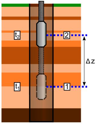
Typically, borehole gravity measurements are collected at discrete intervals by stopping a deployed gravity sensor at predetermined observation depths and performing a stationary measurement [41], before moving to the next observation depth, as illustrated in figure 1. From these measurements, the vertical gradient of gravity, , is determined for the interval of interest by measuring the gravity difference, , and the vertical distance between two consecutive stations, .
Existing borehole gravity sensors used to perform such measurements typically rely on spring-based technology similar to that used in surface-based gravimeters [41]. To allow for operation down boreholes the technology used in surface-based sensors has been miniaturized, equipped with self-leveling capabilities and packaged to fit in narrow diameter borehole tools. For example, the sensor discussed in reference [41] has a radial diameter of 57 mm, can be used to depths of 2,500 m and its self leveling capabilities allow it to be deployed in boreholes inclined up to from vertical. It is typically deployed by conducting wireline cable [41]. Atom interferometry based sensors will need to reach a similar or greater level of deployability to be a competitive tool across all of the applications in which gravity sensing is currently used.
To date, portable atom interferometry based gravity and gravity gradient sensors target surface-based applications and are consequently unsuitable for borehole deployment partly due to radial size and form factor. Several quantum technology-based gravity sensors comprise of a separate control system and sensor head [19, 29]. The control system typically contains the majority of electronics required to run the system, while the sensor head is the part of the system where the measurements take place. These two components are connected via an umbilical, carrying optical and electronic signals. An early implementation could require that in-borehole atom interferometers have a control system on the surface. While this approach will work for shallow boreholes, it is expected that at certain length of the umbilical, systematics associated with having long optical fibres become a limitation (i.e optical power attenuation). As such, a control system capable of being deployed down a borehole will likely be required for operation at much greater depths. Initial implementations of quantum sensors are likely to operate in a similar manner to the existing borehole gravity sensors, stopping at intervals to perform measurements, with the long-term goal of performing measurements while moving [42], such that it can be used as a continuous logging tool. It is also expected that future quantum gravity sensors in borehole would be able to determine the gradient directly [43, 44], reducing errors associated with relative positioning between measurements [41].
As such, the demonstrator constructed here was designed to have the package deployed downhole while the control system remains on the surface. The science package was designed to be deployable via a winch, which was stopped at predefined intervals along the depth of the borehole to perform measurements. This allowed for an assessment of the variability and robustness of the system performance, while performing a simulated but representative survey.

3 Experimental system
The demonstrator consists of two sub-units (see figure 2 a), a control system and a science package, with optical and electrical signals transferred through a 75 m umbilical.
The control system primarily consists of a laser system comprised of two Alter UK REMOTE external-cavity diode lasers (ECDLs) [45], each locked to different atomic transitions. The ECDL used to produce cooling light is offset locked [46] to the ECDL used to produce repump light, which is itself stabilised to a rubidium reference via saturated absorption spectroscopy [47, 48]. The repump is locked to the 87Rb transition and the cooling laser is offset locked 6.4 GHz from the repump, approximately 10 MHz detuned below the transition.
Optical isolators are placed directly after the output of both ECDLs, providing 35 dB isolation to mitigate unwanted back reflections impacting the frequency performance of the ECDLs. The laser system has a pre-aligned saturated absorption spectroscopy setup where all the optics are bonded in place to provide a robust locking signal to stabilise the repump laser frequency. Separately, a small amount of light from both the cooling and repump beams are split off and overlapped on a fast photodiode to provide a beatnote for the offset lock. Various optics distribute laser light to two fibre couplers where the cooling and repump are combined using a 2x2, 90:10 fibre splitter. The laser system can produce a maximum power of 35 mW of cooling and 5 mW of repump light, greater than the 12.8 mW cooling and 1.9 mW repump light input into the umbilical. The laser system is 250 mm x 300 mm x 80 mm in size, weighs 5 kg and uses robust mechanical mounting techniques to increase portability.
The light from this laser is delivered to the science package using a 75 m long polarisation-maintaining optical fibre. This fibre delivers the light to a telescope, which produces a circularly polarised beam with 16.6 mm 1/e2 diameter and an output power of approximately 8 mW, due to attenuation in the umbilical. This beam is collimated and shone directly into the vacuum chamber in which the four 5 mm 5 mm prisms, a quarter wave plate, and a mirror are used to create the six counter-propagating beams required to cool the atoms in all three degrees of freedom (see figure 2 b) [49]. Coils are used to create a quadrupole magnetic field with a linear gradient and null field at the centre of the trapping region. The atoms are loaded into the trap from background atomic vapour, produced under vacuum with a rubidium dispenser. The scattered light from the atom cloud is measured through fluorescence detection. Vacuum pressure is maintained by a 0.4 ls-1 ion pump. The vacuum system, telescope and photo-diode have a form factor of () mm (721) mm .
The science package is (420) mm long and is contained in a (890) mm long stainless steel waterproof enclosure (see figure 2 c), with an outer radius of (60) mm at its widest point and internal radius of (37) mm. The end of this enclosure consists of a solid stainless steel block to reduce buoyancy. This casing allows it to be deployed in cased or uncased boreholes and under waterlogged, muddy or dry borehole conditions. The science package is capable of surviving at temperatures of 60 ∘C, limited by the glass transition temperature of a few 3D printed polylactic acid parts. Replacing these with aluminium would enable operation at higher temperatures. The science package is expected to be waterproof to pressures of bar. The science package does not require centralisation.
4 Deployment campaign
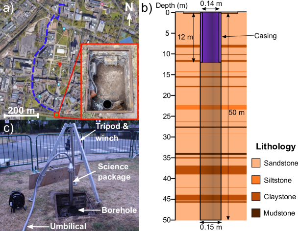
The system was transported in a medium-sized van, a short distance from the lab to the University of Birmingham campus borehole test site [50, 51] for deployment down a borehole as shown in Figure 3 a. During transport the system was unpowered. The borehole itself is 50 m deep and cased to a depth of 12 m with an internal diameter of 14 cm in the cased section (see figure 3 b). The groundwater level was () m below the ground surface level at the time of the survey, determined via the use of a water level meter.
Once at the site, the science package was attached to a cable via the eye holes on the top of the package and lowered into the borehole using a winch and tripod (see figure 3 c). At intervals of (1) m below the surface the system was stopped and 5 MOT loading curves were taken. On average about 2 minutes were spent at each depth to record data, limited by the data capture of the oscilloscope used. Moving the system between depths took approximately 4 minutes, limited by the speed of the winch used.
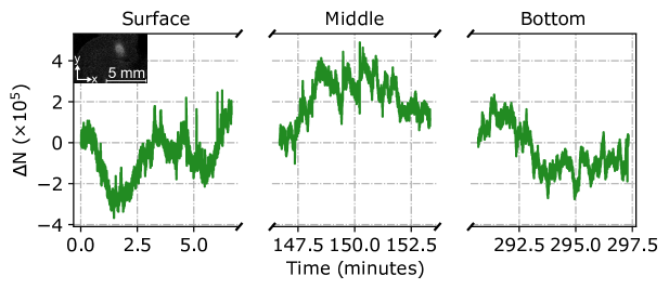
During the survey the stability of the number of atoms in the MOT was measured for 400 s on the surface as well as at the middle, (25.34) m and bottom, (49.34 0.02) m of the borehole. The variation in atom number () relative to the start each of time period is shown in figure 4. The standard deviations at the surface, middle and bottom positions were , and respectively, suggesting that the MOT stability on short time scales in the borehole and on the surface were comparable. The atom number over the whole deployment had a standard deviation of , suggesting that the variation in atom number on short and long time scales was similar.
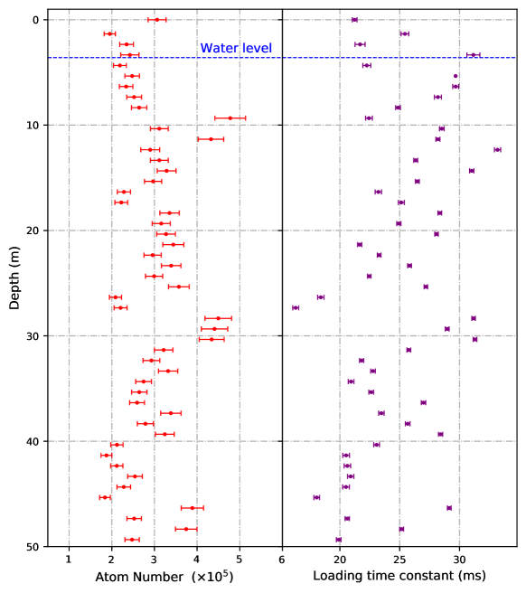
The atom number and loading time constant averaged over 5 curves at each depth can be seen in figure 5. The loading time constant over the course of the deployment had a standard deviation of 5.00 ms, demonstrating a good level of repeatability. The average atom number achieved in the system over the course of the deployment was (, with an average loading time constant of () ms. After reaching a depth of (49.34) m and completing all data acquisition, the system was brought back to the surface. The MOT was maintained throughout the trial and was robust to all of the moving and stopping, with no statistically significant effect on the atom cloud observed when becoming submerged under water or exiting the cased part of the borehole. During the trial the pressure in the vacuum chamber varied between mbar and mbar estimated from the ion pump. This level of variation is typical of performance seen during operation in the lab.
5 Conclusions and outlook
The high-precision and low-drift measurements offered by atom interferometry-based gravity sensors, once realised in borehole-deployable packages, have the potential to open up new sensing capabilities, particularly for long-term monitoring applications such as CCS and hydrological monitoring. To push cold atom-based sensors towards the SWaP profile and robustness that is required for deployment and operation in boreholes, the first borehole-deployable cold atom system has been developed and trialed.
The system was demonstrated to be capable of generating clouds of laser-cooled 87Rb atoms in a system package of (890) mm (120) mm diameter. The system successfully operated down a 50 m deep borehole, generating atom clouds with an average of (3.0 atoms. The standard deviation in atom number performance across the survey was as low as . The performance in terms of number of atoms in the trap and atom number stability were comparable to the device performance on the surface and comparable to MOTs used in some existing cold atom sensors [31, 27, 40].
To upgrade the demonstrator shown here to a full sensor capable of gravity measurements, several extensions to the system (i.e additional functionality in the laser, magnetic shielding) that meet the requirements for operation down a borehole are necessary. These requirements include meeting sufficiently small SWaP and robustness for deployment (e.g. operation while tilted from the vertical), both of which are active research areas. Examples of innovations which could be utilised to produce SWaP optimised sensors for borehole deployment include SWaP optimised 3D printed components [52, 53, 54] and passively pumped vacuum cells [55, 56, 57] to allow for operation in shallow boreholes. Further miniaturisation is required to remove the need for a surface based control system and allow for deployment in deeper boreholes, i.e. compact laser systems [58, 59, 60].
Acknowledgments
We acknowledge support from EPSRC through grants EP/M013294/1 and EP/T001046/1 and innovate UK through 133991 and 133989, as part of the UK National Quantum Technologies Programme. We would like to acknowledge significant support from John Tellam in regards to planning and carrying out the trial. We would like to acknowledge Alter UK for providing the packaged ECDLs, as well as technical support from the University of Birmingham Engineering and Physical Sciences workshop.
Data availability statement
The data that support the findings of this study are available upon reasonable request from the authors.
Statement of contribution
The design and development of the demonstrator was performed by J.V, S.H, K.M, K.W, C.C, A.S, F.H, J.W, B.S, L.E, Ma.H, G.W and Mi.H. The survey design and measurements were contributed by J.V, K.W, F.H, J.W, C.C, A.S and S.R. Data processing was carried out by K.W and J.V. J.V, Mi.H, and K.B. conceived and coordinated the experiment. J.V. and K.W. wrote the manuscript. All authors contributed to the review and improvement of the manuscript.
References
References
- [1] D. Boddice, N. Metje, and G. Tuckwell, “Capability assessment and challenges for quantum technology gravity sensors for near surface terrestrial geophysical surveying,” Journal of Applied Geophysics, vol. 146, pp. 149–159, 2017.
- [2] W. R. Mills, D. C. Stromswold, and L. S. Allen, “Advances in nuclear oil well logging,” Nuclear Geophysics, vol. 5, no. 3, pp. 209–227, 1991.
- [3] J. D. Fairhead and M. E. Odegard, “Advances in gravity survey resolution,” The Leading Edge, vol. 21, no. 1, pp. 36–37, 2002.
- [4] Y. Cho, Y. Cao, Y. Zagayevskiy, T. Wong, and Y. Munoz, “Kriging-based monitoring of reservoir gas saturation distribution using time-lapse multicomponent borehole gravity measurements: Case study, Hastings Field,” Journal of Petroleum Science and Engineering, vol. 190, p. 107054, 2020.
- [5] L. R. Lines, H. Tan, and A. K. Schultz, “Cross-borehole analysis of velocity and density,” Geoexploration, vol. 28, no. 3, pp. 183–191, 1991. Borehole Geophysics.
- [6] L. A. Beyer and F. G. Clutsom, “Borehole gravity survey in the Dry Piney oil and gas field, Big Piney-La Barge area, Sublette County, Wyoming,” U.S. Geol. Surv., Oil Gas Invest., Chart; (United States), 1 1978.
- [7] A. G. Nekut, “Borehole gravity gradiometry,” GEOPHYSICS, vol. 54, no. 2, pp. 225–234, 1989.
- [8] L. A. Beyer and F. Clutsom, “Density and porosity of oil reservoirs and overlying formations from borehole gravity measurements, Gebo Oil Field, Hot Springs County, Wyoming,” 1978.
- [9] R. B. Halley and J. W. Schmoker, “High-Porosity Cenozoic Carbonate Rocks of South Florida: Progressive Loss of Porosity with Depth,” AAPG Bulletin, vol. 67, pp. 191–200, 02 1983.
- [10] T. LaFehr, “Rock density from borehole gravity surveys,” Geophysics, vol. 48, no. 3, pp. 341–356, 1983.
- [11] D. Appriou, A. Bonneville, Q. Zhou, and E. Gasperikova, “Time-lapse gravity monitoring of CO2 migration based on numerical modeling of a faulted storage complex,” International Journal of Greenhouse Gas Control, vol. 95, p. 102956, 2020.
- [12] K. Dodds, R. Krahenbuhl, A. Reitz, Y. Li, and S. Hovorka, “Evaluating time-lapse borehole gravity for CO2 plume detection at SECARB Cranfield,” International Journal of Greenhouse Gas Control, vol. 18, pp. 421–429, 2013.
- [13] J. Thomas and P. Vogel, “Testing the inverse-square law of gravity in boreholes at the Nevada Test Site,” Phys. Rev. Lett., vol. 65, pp. 1173–1176, Sep 1990.
- [14] M. E. Ander, M. A. Zumberge, T. Lautzenhiser, R. L. Parker, C. L. V. Aiken, M. R. Gorman, M. M. Nieto, A. P. R. Cooper, J. F. Ferguson, E. Fisher, G. A. McMechan, G. Sasagawa, J. M. Stevenson, G. Backus, A. D. Chave, J. Greer, P. Hammer, B. L. Hansen, J. A. Hildebrand, J. R. Kelty, C. Sidles, and J. Wirtz, “Test of Newton’s inverse-square law in the Greenland ice cap,” Phys. Rev. Lett., vol. 62, pp. 985–988, Feb 1989.
- [15] A. Hinton, M. Perea-Ortiz, J. Winch, J. Briggs, S. Freer, D. Moustoukas, S. Powell-Gill, C. Squire, A. Lamb, C. Rammeloo, B. Stray, G. Voulazeris, L. Zhu, A. Kaushik, Y.-H. Lien, A. Niggebaum, A. Rodgers, A. Stabrawa, D. Boddice, S. R. Plant, G. W. Tuckwell, K. Bongs, N. Metje, and M. Holynski, “A portable magneto-optical trap with prospects for atom interferometry in civil engineering,” Philosophical Transactions of the Royal Society A: Mathematical, Physical and Engineering Sciences, vol. 375, no. 2099, p. 20160238, 2017.
- [16] M. Kasevich and S. Chu, “Atomic interferometry using stimulated raman transitions,” Phys. Rev. Lett., vol. 67, pp. 181–184, Jul 1991.
- [17] Peters, Achim, Chung, K. Yeow, S. Chu, and Steven, “Measurement of gravitational acceleration by dropping atoms,” Nature, vol. 400, pp. 849–, 08 1999.
- [18] K. Bongs, M. Holynski, J. Vovrosh, P. Bouyer, G. Condon, E. Rasel, C. Schubert, W. P. Schleich, and A. Roura, “Taking atom interferometric quantum sensors from the laboratory to real-world applications,” Nat Rev Phys, vol. 1, no. 12, p. 731–739, 2019.
- [19] B. Stray, A. Lamb, A. Kaushik, J. Vovrosh, A. Rodgers, J. Winch, F. Hayati, D. Boddice, A. Stabrawa, A. Niggebaum, M. Langlois, Y.-H. Lien, S. Lellouch, S. Roshanmanesh, K. Ridley, G. d. Villiers, G. Brown, Cross, G. Tuckwell, A. Faramarzi, N. Metje, K. Bongs, and M. Holynski, “Quantum sensing for gravitational cartography,” Nature, vol. 602, pp. 590–594, 2022.
- [20] S. M. Dickerson, J. M. Hogan, A. Sugarbaker, D. M. S. Johnson, and M. A. Kasevich, “Multiaxis inertial sensing with long-time point source atom interferometry,” Phys. Rev. Lett., vol. 111, p. 083001, Aug 2013.
- [21] A. Peters, K. Y. Chung, and S. Chu, “High-precision gravity measurements using atom interferometry,” Metrologia, vol. 38, pp. 25–61, feb 2001.
- [22] Z.-K. Hu, B.-L. Sun, X.-C. Duan, M.-K. Zhou, L.-L. Chen, S. Zhan, Q.-Z. Zhang, and J. Luo, “Demonstration of an ultrahigh-sensitivity atom-interferometry absolute gravimeter,” Phys. Rev. A, vol. 88, p. 043610, Oct 2013.
- [23] P. Asenbaum, C. Overstreet, M. Kim, J. Curti, and M. A. Kasevich, “Atom-interferometric test of the equivalence principle at the level,” Phys. Rev. Lett., vol. 125, p. 191101, Nov 2020.
- [24] L. Morel, Z. Yao, P. Cladé, and S. Guellati-Khélifa, “Determination of the fine-structure constant with an accuracy of 81 parts per trillion,” Nature, vol. 588, pp. 61–65, Dec. 2020.
- [25] R. H. Parker, C. Yu, W. Zhong, B. Estey, and H. Müller, “Measurement of the fine-structure constant as a test of the standard model,” Science (New York, N.Y.), vol. 360, p. 191—195, April 2018.
- [26] G. Rosi, F. Sorrentino, L. Cacciapuoti, M. Prevedelli, and G. M. Tino, “Precision measurement of the Newtonian gravitational constant using cold atoms,” Nature, vol. 510, pp. 518–521, 2014.
- [27] Y. Bidel, N. Zahzam, C. Blanchard, A. Bonnin, M. Cadoret, A. Bresson, D. Rouxel, and M. Lequentrec-Lalancette, “Absolute marine gravimetry with matter-wave interferometry,” Nature Communications, vol. 9, 2018.
- [28] D. Becker, M. D. Lachmann, S. T. Seidel, H. Ahlers, A. N. Dinkelaker, J. Grosse, O. Hellmig, H. Müntinga, V. Schkolnik, T. Wendrich, A. Wenzlawski, B. Weps, R. Corgier, T. Franz, N. Gaaloul, W. Herr, D. Lüdtke, M. Popp, S. Amri, H. Duncker, M. Erbe, A. Kohfeldt, A. Kubelka-Lange, C. Braxmaier, E. Charron, W. Ertmer, M. Krutzik, C. Lämmerzahl, A. Peters, W. P. Schleich, K. Sengstock, R. Walser, A. Wicht, P. Windpassinger, and E. M. Rasel, “Space-borne Bose–Einstein condensation for precision interferometry,” Nature, vol. 562, 2018.
- [29] V. Menoret, P. Vermeulen, N. L. Moigne, S. Bonvalot, P. Bouyer, A. Landragin, and B. Desruelle, “Gravity measurements below with a transportable absolute quantum gravimeter,” Sci. Rep., vol. 8, no. 12300, 2018.
- [30] X. Wu, Z. Pagel, B. S. Malek, T. H. Nguyen, F. Zi, D. S. Scheirer, and H. Müller, “Gravity surveys using a mobile atom interferometer,” Science Advances, vol. 5, no. 9, 2019.
- [31] Y. Bidel, N. Zahzam, A. Bresson, C. Blanchard, M. Cadoret, A. V. Olesen, and R. Forsberg, “Absolute airborne gravimetry with a cold atom sensor,” Journal of Geodesy, vol. 94, 2020.
- [32] J. Guo, S. Ma, C. Zhou, J. Liu, B. Wang, D. Pan, and A. H. Mao, “Vibration compensation for a vehicle-mounted atom gravimeter,” 2021.
- [33] L. Earl, J. Vovrosh, M. Wright, D. Roberts, J. Winch, M. Perea-Ortiz, A. Lamb, F. Hayati, P. Griffin, N. Metje, K. Bongs, and M. Holynski, “Demonstration of a compact magneto-optical trap on an unstaffed aerial vehicle,” Atoms, vol. 10, no. 1, 2022.
- [34] H. Wang, K. Wang, Y. Xu, Y. Tang, B. Wu, B. Cheng, L. Wu, Y. Zhou, K. Weng, D. Zhu, P. Chen, K. Zhang, and Q. Lin, “A truck-borne system based on cold atom gravimeter for measuring the absolute gravity in the field,” Sensors, vol. 22, no. 16, 2022.
- [35] S. Templier, P. Cheiney, Q. d’Armagnac de Castanet, B. Gouraud, H. Porte, F. Napolitano, P. Bouyer, B. Battelier, and B. Barrett, “Tracking the vector acceleration with a hybrid quantum accelerometer triad,” Science Advances, vol. 8, no. 45, p. eadd3854, 2022.
- [36] Y. A. Kozlovsky and N. Adrianov, The superdeep well of the Kola Peninsula. Springer, 1987.
- [37] A. M. Steane, M. Chowdhury, and C. J. Foot, “Radiation force in the magneto-optical trap,” J. Opt. Soc. Am. B, vol. 9, pp. 2142–2158, Dec 1992.
- [38] S. A. Diddams, T. Udem, J. Bergquist, E. Curtis, R. Drullinger, L. Hollberg, W. M. Itano, W. Lee, C. Oates, K. Vogel, and D. Wineland, “An optical clock based on a single trapped 199Hg+ ion,” Science, vol. 293, no. 5531, pp. 825–828, 2001.
- [39] F. A. Narducci, A. T. Black, and J. H. Burke, “Advances toward fieldable atom interferometers,” Advances in Physics: X, vol. 7, no. 1, p. 1946426, 2022.
- [40] N. Behbood, F. Martin Ciurana, G. Colangelo, M. Napolitano, M. W. Mitchell, and R. J. Sewell, “Real-time vector field tracking with a cold-atom magnetometer,” Applied Physics Letters, vol. 102, no. 17, p. 173504, 2013.
- [41] C. Nind, J. MacQueen, R. Wasylechko, M. Chemam, and C. Nackers, “GRAVILOG -an update on the development and use of borehole gravity for mining exploration,” pp. 1–5, 2013.
- [42] B. Adams, C. Macrae, M. Entezami, K. Ridley, A. Kubba, Y.-H. Lien, S. Kinge, and K. Bongs, “The development of a high data rate atom interferometric gravimeter (hidrag) for gravity map matching navigation,” in 2021 IEEE International Symposium on Inertial Sensors and Systems (INERTIAL), pp. 1–4, 2021.
- [43] M. J. Snadden, J. M. McGuirk, P. Bouyer, K. G. Haritos, and M. A. Kasevich, “Measurement of the earth’s gravity gradient with an atom interferometer-based gravity gradiometer,” Phys. Rev. Lett., vol. 81, pp. 971–974, Aug 1998.
- [44] J. M. McGuirk, G. T. Foster, J. B. Fixler, M. J. Snadden, and M. A. Kasevich, “Sensitive absolute-gravity gradiometry using atom interferometry,” Phys. Rev. A, vol. 65, p. 033608, Feb 2002.
- [45] W. Dorward, S. T. Lee, D. Bremner, S. Robertson, B. Jones, C. Carson, and L. McKnight, “The application of telecoms-style packaging techniques to narrow linewidth laser modules for quantum technologies,” in Components and Packaging for Laser Systems V, vol. 10899 of Society of Photo-Optical Instrumentation Engineers (SPIE) Conference Series, p. 1089908, Mar. 2019.
- [46] U. Schünemann, H. Engler, R. Grimm, M. Weidemüller, and M. Zielonkowski, “Simple scheme for tunable frequency offset locking of two lasers,” Review of Scientific Instruments, vol. 70, no. 1, pp. 242–243, 1999.
- [47] K. I. Lee, J. A. Kim, H. R. Noh, and W. Jhe, “Single-beam atom trap in a pyramidal and conical hollow mirror,” Opt. Lett., vol. 21, pp. 1177–1179, Aug 1996.
- [48] K. B. MacAdam, A. Steinbach, and C. Wieman, “A narrow‐band tunable diode laser system with grating feedback, and a saturated absorption spectrometer for Cs and Rb,” American Journal of Physics, vol. 60, no. 12, pp. 1098–1111, 1992.
- [49] J. Vovrosh, L. Earl, H. Thomas, J. Winch, B. Stray, K. Ridley, M. Langlois, K. Bongs, and M. Holynski, “Reduction of background scattered light in vacuum systems for cold atoms experiments,” AIP Advances, vol. 10, no. 10, p. 105125, 2020.
- [50] J. E. Bouch, E. Hough, S. J. Kemp, J. A. McKervey, G. Williams, and R. B. Gresswell, “Sedimentary and diagenetic environments of the wildmoor sandstone formation (uk) : implications for groundwater and contaminant transport, and sand production,” in Fluid flow and solute movements in sandstones : the onshore UK Permo-Triassic red bed sequence (R. Barker and J. Tellam, eds.), vol. 263 of Geological Society Special Publications, pp. 129–153, London, UK: Geological Society of London, 2006.
- [51] M. S. Riley, J. H. Tellam, R. B. Greswell, V. Durand, and M. F. Aller, “Convergent tracer tests in multilayered aquifers: The importance of vertical flow in the injection borehole,” Water Resources Research, vol. 47, no. 7, 2011.
- [52] J. Vovrosh, G. Voulazeris, P. G. Petrov, J. Zou, Y. Gaber, L. Benn, D. Woolger, M. M. Attallah, V. Boyer, K. Bongs, and M. Holynski, “Additive manufacturing of magnetic shielding and ultra-high vacuum flange for cold atom sensors,” Sci. Rep., vol. 8, 2018.
- [53] N. Cooper, L. Coles, S. Everton, I. Maskery, R. Campion, S. Madkhaly, C. Morley, J. O’Shea, W. Evans, R. Saint, P. Krüger, F. Oručević, C. Tuck, R. Wildman, T. Fromhold, and L. Hackermüller, “Additively manufactured ultra-high vacuum chamber for portable quantum technologies,” Addit. Manuf., vol. 40, p. 101898, 2021.
- [54] S. Madkhaly, L. Coles, C. Morley, C. Colquhoun, T. Fromhold, N. Cooper, and L. Hackermüller, “Performance-optimized components for quantum technologies via additive manufacturing,” PRX Quantum, vol. 2, p. 030326, Aug 2021.
- [55] B. J. Little, G. W. Hoth, J. Christensen, C. Walker, D. J. De Smet, G. W. Biedermann, J. Lee, and P. D. D. Schwindt, “A passively pumped vacuum package sustaining cold atoms for more than 200 days,” AVS Quantum Science, vol. 3, no. 3, p. 035001, 2021.
- [56] J. Rushton, M. Aldous, and M. Himsworth, “Contributed review: The feasibility of a fully miniaturized magneto-optical trap for portable ultracold quantum technology,” Review of Scientific Instruments, vol. 85, no. 12, p. 121501, 2014.
- [57] O. S. Burrow, P. F. Osborn, E. Boughton, F. Mirando, D. P. Burt, P. F. Griffin, A. S. Arnold, and E. Riis, “Stand-alone vacuum cell for compact ultracold quantum technologies,” Applied Physics Letters, vol. 119, no. 12, p. 124002, 2021.
- [58] F. Theron, Y. Bidel, E. Dieu, N. Zahzam, M. Cadoret, and A. Bresson, “Frequency-doubled telecom fiber laser for a cold atom interferometer using optical lattices,” Optics Communications, vol. 393, pp. 152–155, 2017.
- [59] Q. Luo, H. Zhang, K. Zhang, X.-C. Duan, Z.-K. Hu, L.-L. Chen, and M.-K. Zhou, “A compact laser system for a portable atom interferometry gravimeter,” Review of Scientific Instruments, vol. 90, no. 4, p. 043104, 2019.
- [60] X. Wu, F. Zi, J. Dudley, R. J. Bilotta, P. Canoza, and H. Müller, “Multiaxis atom interferometry with a single-diode laser and a pyramidal magneto-optical trap,” Optica, vol. 4, no. 12, pp. 1545–1551, 2017.
- [61] T. Kovachy, P. Asenbaum, C. Overstreet, C. Donnelly, S. Dickerson, A. Sugarbaker, J. Hogan, and M. Kasevich, “Quantum superposition at the half-metre scale,” Nature, vol. 528, no. 7583, pp. 530–533, 2015.
- [62] L. Salvi, N. Poli, V. Vuletić, and G. M. Tino, “Squeezing on momentum states for atom interferometry,” Phys. Rev. Lett., vol. 120, p. 033601, Jan 2018.
- [63] A. Sugarbaker, S. M. Dickerson, J. M. Hogan, D. M. S. Johnson, and M. A. Kasevich, “Enhanced atom interferometer readout through the application of phase shear,” Phys. Rev. Lett., vol. 111, p. 113002, Sep 2013.
- [64] D. Yankelev, C. Avinadav, N. Davidson, and O. Firstenberg, “Atom interferometry with thousand-fold increase in dynamic range,” Science Advances, vol. 6, no. 45, p. eabd0650, 2020.
- [65] P. Berg, S. Abend, G. Tackmann, C. Schubert, E. Giese, W. P. Schleich, F. A. Narducci, W. Ertmer, and E. M. Rasel, “Composite-light-pulse technique for high-precision atom interferometry,” Phys. Rev. Lett., vol. 114, p. 063002, Feb 2015.
- [66] N. Mielec, M. Altorio, R. Sapam, D. Horville, D. Holleville, L. A. Sidorenkov, A. Landragin, and R. Geiger, “Atom interferometry with top-hat laser beams,” Applied Physics Letters, vol. 113, no. 16, p. 161108, 2018.
- [67] P. J. Hobson, J. Vovrosh, B. Stray, M. Packer, J. Winch, N. Holmes, F. Hayati, K. McGovern, R. Bowtell, M. J. Brookes, K. Bongs, T. M. Fromhold, and M. Holynski, “Bespoke magnetic feld design for a magnetically shielded cold atom interferometer,” Sci Rep, vol. 12, p. 10520, 2022.
- [68] H. Shang, D. Pan, X. Zhang, X. Xue, T. Shi, and J. Chen, “Ultrastable laser referenced on velocity-grating atom interferometry,” Phys. Rev. A, vol. 105, p. L051101, May 2022.