In-situ amplification of spin echoes within a kinetic inductance parametric amplifier
Abstract
The use of superconducting micro-resonators in combination with quantum-limited Josephson parametric amplifiers has in recent years lead to more than four orders of magnitude improvement in the sensitivity of pulsed Electron Spin Resonance (ESR) measurements. So far, the microwave resonators and amplifiers have been designed as separate components, largely due to the incompatibility of Josephson junction-based devices with even moderate magnetic fields. This has led to complex spectrometers that operate under strict environments, creating technical barriers for the widespread adoption of the technique. Here we circumvent this issue by inductively coupling an ensemble of spins directly to a weakly nonlinear microwave resonator, which is engineered from a magnetic field-resilient thin superconducting film. We perform pulsed ESR measurements with a pL effective mode volume and amplify the resulting spin signal using the same device, ultimately achieving a sensitivity of spins in a single-shot Hahn echo measurement at a temperature of 400 mK. We demonstrate the combined functionalities at fields as large as 254 mT, highlighting the technique’s potential for application under more conventional ESR operating conditions.
I Introduction
Electron Spin Resonance (ESR) spectroscopy is a technique used throughout Physics, Biology, Chemistry and Medicine to study materials through their paramagnetic properties [1]. To detect ESR, conventional spectrometers use a cavity to capture the weak microwave signal that is induced by the transverse magnetization of an ensemble of spins precessing in an external magnetic field. The magnitude of this signal is determined by the number of resonant spins coupled to the cavity (), the spin-cavity coupling strength () and the quality factor () of the cavity. The coupling strength depends on the degree of confinement of the magnetic energy in the microwave mode, , where is the magnetic mode volume [2]. Conventional ESR spectrometers utilize three-dimensional microwave cavities where , with the wavelength of the resonant mode. An alternative approach is to use micro-resonator circuits, where the modes are confined in quasi-one-dimensional structures, such that and is considerably enhanced [3, 4]. Constructing these mirco-resonator circuits from superconducting materials also allows them to achieve high quality factors, which further enhances the spin sensitivity [3, 5].
The superconducting circuit resonator is just one tool from the field of circuit Quantum Electrodynamics (cQED) that has recently been applied to ESR. Josephson Parametric Amplifiers (JPAs) [6] have also been integrated into custom ESR spectrometers and used to push detection sensitivities to the quantum limit [7, 8], where the noise in the measurement of a spin ensemble is set by vacuum fluctuations of the electromagnetic field. The combination of high- superconducting microwave resonators and JPAs has ultimately resulted in sensitivities as low as 120 spins for a single Hahn echo measured at 10 mK, corresponding to an absolute sensitivity of 12 spins/ [9].
Another approach taken to improve ESR measurement sensitivity has been to couple the spin ensemble directly to non-linear circuits. An early example of this involved coupling an ensemble of NV-centers in diamond to a superconducting transmon qubit, achieving a sensitivity of spins/ [10]. This was recently improved to 20 spins/ using a flux-qubit read out via an on-chip Josephson bifurcation amplifier [11]. However, both of these approaches operate in a mode more analogous to continuous wave ESR spectroscopy. The efforts also mirror recent directions in the superconducting qubit community to engineer high efficiency measurements by reducing or eliminating the insertion loss between the system being measured and the first cryogenic amplifier [12, 13].
Despite these successes, previous works have all relied on technologies utilizing Josephson junctions, which are not magnetic field-resilient. This restricts the use of on-chip detection methods to low magnetic fields. Higher magnetic fields can be applied when using JPAs off-chip, where they are contained in magnetically-shielded boxes and connected to the ESR cavity via coaxial cables and microwave circulators. The disadvantage of this approach is that the extra components introduce additional insertion loss, which inevitably attenuates the spin signals before they are amplified. Moreover, JPAs typically display gain compression for input powers dBm [14], which leads to signal distortion and limits the power that can be detected in pulsed ESR experiments.
In this work we demonstrate that these limitations can be overcome by using a Kinetic Inductance Parametric Amplifier (KIPA) [15] coupled directly to an ensemble of spins. The KIPA is a weakly non-linear micro-resonator engineered from the high kinetic inductance superconductor niobium titanium nitride (NbTiN), which is a material known to produce high- and magnetic field-resilient resonators [16, 17]. The weak non-linearity of the KIPA allows it to act as both the ESR cavity and first-stage amplifier, where spin echo signals are amplified in-situ via three wave mixing with an applied pump tone. Compared to using a low-noise cryogenic transistor amplifier as the first stage amplifier, we demonstrate an enhancement to the signal to noise ratio of 7.5 at a magnetic field of 6.8 mT and 3.8 at 250 mT, corresponding to a more than order of magnitude reduction in measurement times.
II Results
II.1 Device Design and Characterization
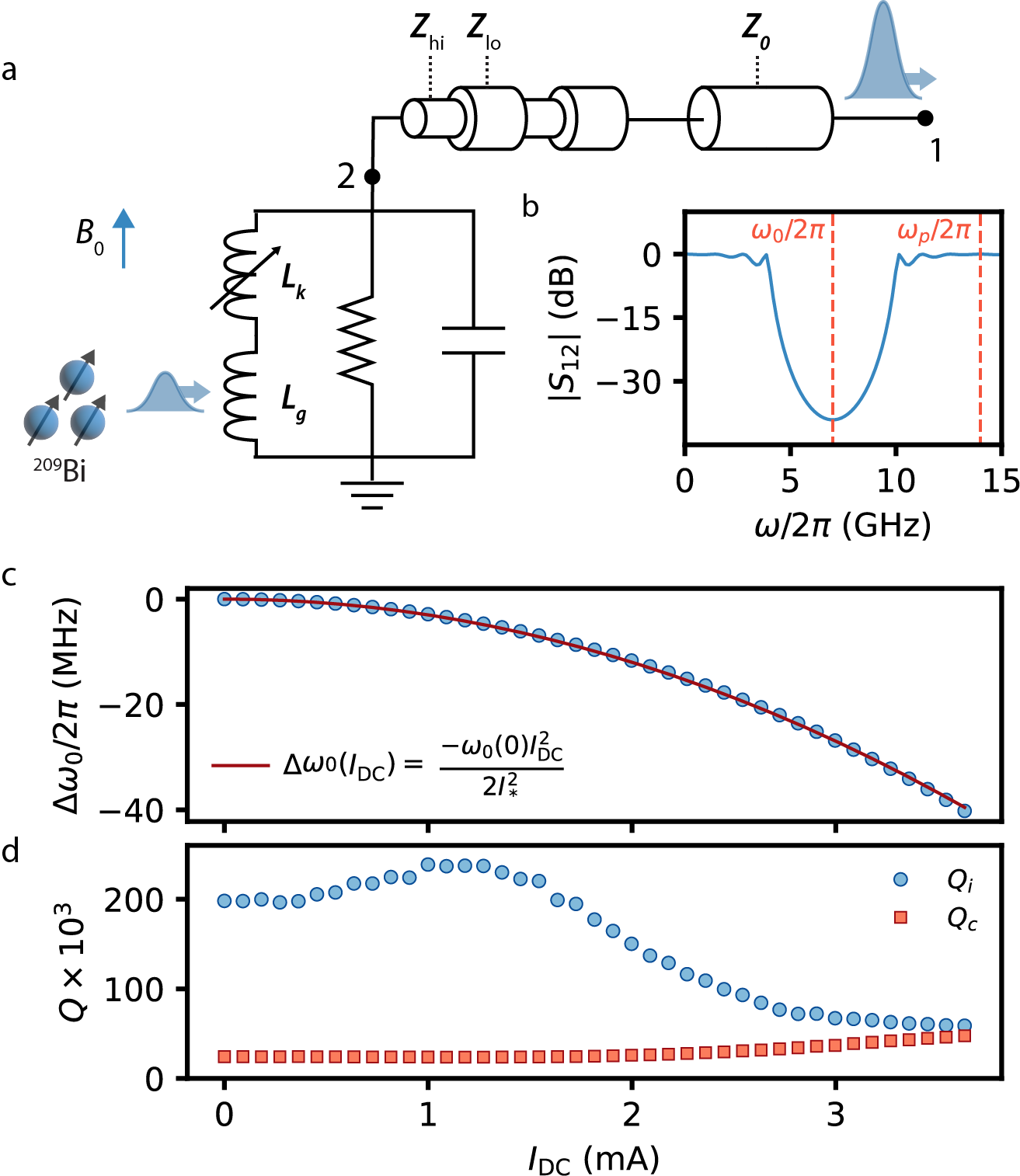
The device utilized in this work is based on a Kinetic Inductance Parametric Amplifier [15] and consists of a Coplanar Waveguide (CPW) resonator positioned at the end of a Stepped Impedance Filter (SIF), as depicted in Fig. 1a. The SIF is constructed from a series of eight impedance transformers with alternating high- () and low-impedance () (see Supplementary Materials for detailed design specifications). The filter is analogous to an optical Bragg mirror and has been used to create Purcell filters for superconducting qubits [18] and 1D-photonic crystals [19]. We use the SIF to confine the resonator’s mode while maintaining a galvanic connection to it; this enables the resonance frequency () to be tuned by a DC-current () [20, 21, 22] and facilitates amplification via three wave mixing (3WM) when a pump with frequency is introduced [23, 15]. The predicted frequency-dependent transmission of a SIF can be calculated from ABCD matrices [24] and is plotted according to our design in Fig. 1b; it shows a deep stopband centered on which serves to isolate the resonant mode from the measurement port. Notably, the filter has passbands at DC and at , so that both and the pump can be efficiently passed to the resonator.
The device is fabricated from a 50 nm thick film of NbTiN on an isotopically-enriched 28Si substrate that has been ion implanted with bismuth donors at a concentration of over a depth of approximately . The width of the resonator (i.e. the final segment) center conductor is m with m gaps to ground and is designed to have a fundamental resonance at GHz with an impedance of . The film exhibits a large kinetic inductance due to the inertia of the Cooper pairs, which displays a weak non-linear dependence on the total current according to [25]:
| (1) |
where for our NbTiN film (see Supplementary Materials for details) and is a constant related to the critical current [15]. This non-linearity allows the resonant frequency to be tuned through the application of a DC current and facilitates amplification. The spins couple to the magnetic field produced by the device, or equivalently its geometric inductance . It is therefore important to balance the amount of kinetic and geometric inductance present to ensure a sufficient non-linearity for performing amplification without substantially reducing the coupling to the spins (a detailed discussion on this is presented in the Supplementary Materials).
We use a Vector Network Analyzer (VNA) to measure the response of the device in reflection () without amplification and determine the experimental value of to be 7.233 GHz at mA. We also determine the internal quality factor () and coupling quality factor () by fitting the combined amplitude and phase response [26] and display the dependence of the fit results in Figs. 1c-d. The device can be tuned over a range of 40 MHz by applying up to mA, before the superconducting film transitions to the normal state. We expect a quadratic dependence of the change in resonance frequency with the applied DC current , which allows us to extract mA for this device. decreases monotonically for mA and grows by a factor of two; the combined effect is that the device approaches critical coupling () as is raised.
II.2 Pulsed ESR Measurements
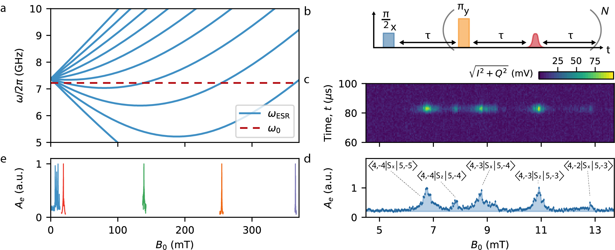
Our measurements are performed at a temperature of mK, where the 209Bi donors bind one additional valence electron compared to the surrounding Si atoms. The donor-bound electron and its nucleus are coupled via the contact hyperfine interaction, , where GHz [27] and () represents the electron (nuclear) spin operator. At fields mT, the contact hyperfine interaction is of comparable strength to the Zeeman interaction, , where GHz/T and MHz/T. Here the eigenstates of the spin Hamiltonian are best described by the total spin and its projection onto , . The twenty electron-nuclear states are divided into an upper manifold of eleven states with and a lower manifold of nine states with . The ESR-allowed transitions, which are driven through the spin operator, are calculated and displayed in Fig. 2a, where we plot the frequency of the transitions as a function of the magnetic field.
The static magnetic field is applied in the plane of the device and parallel to the long-axis of the resonator. This alignment is chosen so that the magnetic field produced by the resonator which drives spin resonance is perpendicular to for the spins located underneath the resonator, in order to probe the ESR transitions. To perform ESR, we tune so that (horizontal dashed line in Fig. 2a).
We detect the spins using a Carr-Purcell-Meiboom-Gill (CPMG) pulse sequence (Fig. 2b). Due to the long spin coherence times of 209Bi donors in isotopically enriched 28Si [28], we are able to repeatedly refocus the ensemble, collecting a spin echo each time we do so. We use refocusing pulses and average the echo signals to increase the signal-to-noise-ratio (SNR) of our measurement [29]. The result over a small field range is shown in Fig. 2c, where we plot the amplitude of the homodyne-demodulated signal, , as a function of . In Fig. 2d we also plot the integrated echo signal , where is the duration of the spin echo signal. By comparing the measured spectrum to an exact diagonalization of the Hamiltonian , we can identify the transitions present in this field sweep. Three of the transitions are coupled by the operator. These are the typical ESR transitions that were expected for the orientation of the resonator and the external magnetic field. Two of the transitions, however, are coupled by the spin operator. In the basis these correspond to transitions of the type and are driven by a longitudinal magnetic field (i.e. when is parallel to ). Though they are forbidden at high field, these transitions can be observed at low field due to the hyperfine coupling, [30]. This suggests that the resonant mode of our device is not fully confined to the last section. Finite element simulations confirm this (see Supplementary Materials) and show that at there is an appreciable field in the last segment of the SIF, which is oriented perpendicular to the resonator (see Supplementary Materials for a full device schematic) and where for spins located underneath the inner conductor of the CPW.
In addition to the five transitions measured at mT, we demonstrate the ability to measure each transition out to mT (Fig. 2e). Aside from the use of NbTiN as the superconducting material and the in-plane alignment of , we did not implement any specific features to enhance our device’s compatibility with magnetic fields, such as the inclusion of vortex pinning sites [17]. By converting the magnetic field to the equivalent ESR frequency of a free electron, we see that this range of fields encompasses the X-band frequency range ( GHz) common for commercial ESR spectrometers.
II.3 In-Situ Amplification of Spin Echoes
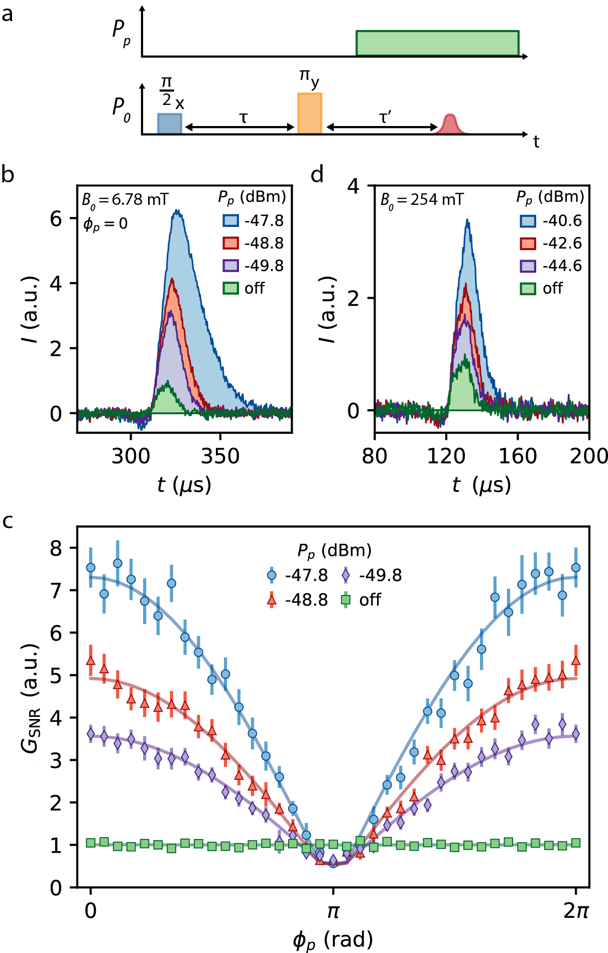
We now seek to use the weak non-linearity of the NbTiN film to perform in-situ amplification of the spin echo signals. A pump tone is applied to the device at a frequency of and amplification occurs as energy transfers from the pump to the spin echo signal at . The quadratic dependence of the kinetic inductance with current (see Eq. 1) naturally lends itself to a four wave mixing (4WM) process, where energy conservation requires , with corresponding to the ‘idler’ frequency – a tone produced during amplification. The application of a DC current lowers the order of the non-linearity [31, 23, 15] and enables three wave mixing processes, where energy conservation dictates . 3WM is preferable in amplification as it provides a large spectral separation between the pump and signal, allowing the pump to be filtered out of the detection chain. In addition, for kinetic inductance amplifiers 3WM is a more efficient process than 4WM, requiring lower pump powers for equivalent gains [23]. To amplify the spin echoes in-situ via 3WM, we first DC current bias the device with mA. Next, we apply a standard Hahn echo pulse sequence with the addition of a pump tone at the frequency and power , which is sent s following the trailing edge of the refocusing pulse (Fig. 3a). The device therefore functions as a resonator during the delivery of the spin control pulses and as a resonant parametric amplifier when the spin echoes are detected. For a pump frequency precisely twice the signal frequency (as used here), the signal and idler tones become degenerate and the gain depends on the relative phase between the signal and pump [15]. In Fig. 3b we compare spin echoes measured at mT on the transition. The echoes are aligned along the signal quadrature and presented for several different . The pump phase is tuned at each to maximize the gain and therefore spin echo amplitude. For dBm, the maximum echo amplitude is greater than times larger than that of an equivalent measurement with the pump turned off, where the first stage amplifier corresponds to a cryogenic low noise high electron mobility transistor (HEMT) amplifier (see Supplementary Materials for setup details). Interestingly, the duration of the echo also lengthens when is increased. We attribute this to the finite Gain-Bandwidth Product (GBP) of the KIPA that is common to many resonant parametric amplifiers, which in our measurement extends the length of time it takes for the amplified intracavity field to decay.
II.4 Signal to Noise Ratio
We define the amplitude SNR of the Hahn echo measurements as:
| (2) |
where the and subscripts refer the the experimental pulse sequence (which produces a spin echo) and a blank pulse sequence (which gives a measure of the noise), respectively. For the blank sequence, we omit the refocusing pulse from the Hahn echo sequence so that no spin echo is produced. The amplitude SNR is therefore the ratio of the mean amplitude of the spin echo and the root-mean-square (RMS) of the noise.
In our experiments the duration of the spin echo depends on , so to calculate the SNR we keep the window fixed to the duration of the shortest echo, corresponding to the measurement with the pump off (e.g. s in Fig. 3b). This ensures that the bandwidth of the noise is equal when we compare the SNR for measurements taken with different . The improvement to the amplitude SNR when parametrically pumping the device is then given by:
| (3) |
In Fig. 3c we demonstrate that is phase dependent, displaying a period of with the pump phase . This is evidence that the amplifier indeed acts in degenerate mode. For these measurements we align the maximum amplitudes of the different traces at , where we find at the highest pump power dBm. At this power we also measure , demonstrating that the spin echo signal is deamplified for certain phases.
In Fig. 3d we show similar measurements taken at mT, corresponding to the spin transition. Due to a gradual decline of as we increase , we choose to work with mA where GHz, and . At this field we manage to enhance the amplitude of the spin echo signal by up to a factor of relative to a measurement without the pump applied, corresponding to . Notably, this enhancement is achieved without explicitly controlling for . The SNR of the spin signal at this transition was smaller than at 6.78 mT, requiring us to increase the number of measurement averages. Due to the limited hold time of our pumped 3He cryostat, this prevented us from measuring as a function of . Instead, we kept the microwave sources phase locked but randomized between repetitions, such that the we report is effectively the average of . This SNR enhancement could therefore be improved by a factor of 2 with appropriate choice of pump phase.
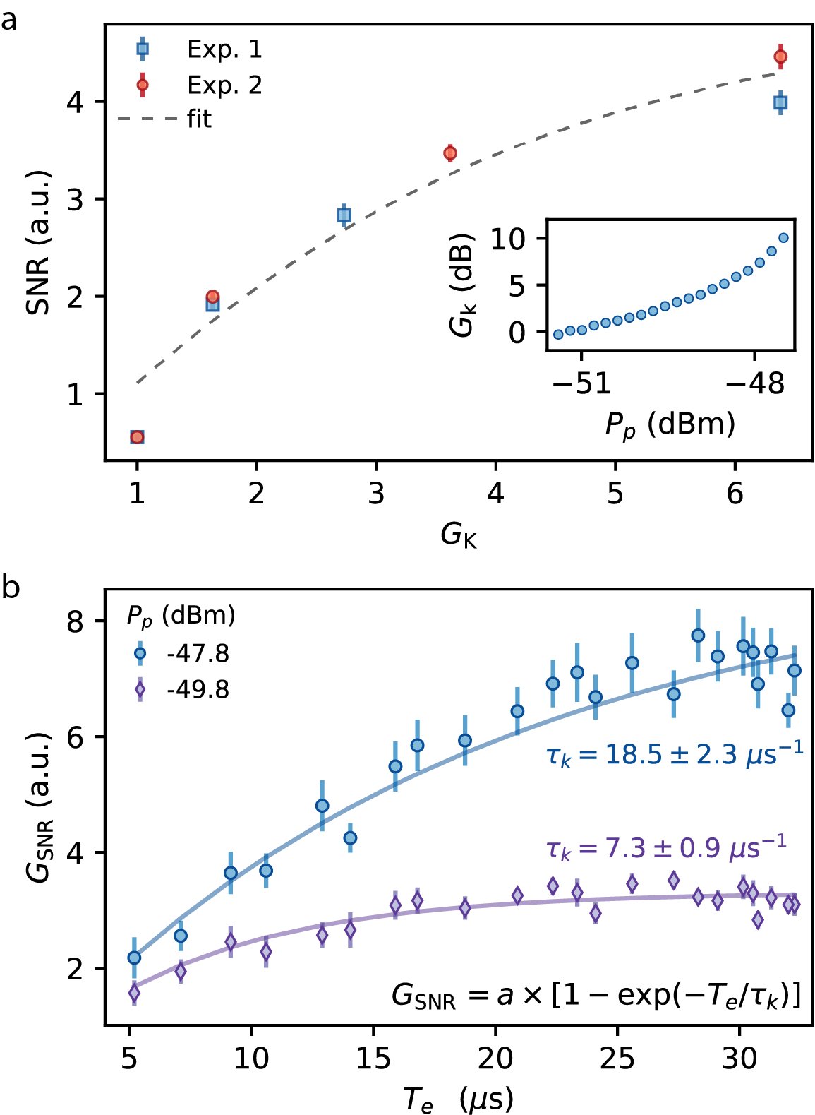
Next we investigate the dependence of on the amplitude gain of the amplifier (, Fig. 4a). is measured using a spectrum analyzer to assess the degenerate gain of a coherent signal with frequency reflected off the input of the KIPA and with chosen to maximize the gain (inset of Fig. 4a). We see that initially grows rapidly with , but begins to saturate at high . This can be explained by considering the three contributions to the total noise: noise on the spin echo signal itself (), e.g. vacuum, thermal and spontaneous emission noise, noise added by the KIPA (), and noise added by the components following the KIPA (). As we show using a model derived from cavity input-output theory in the Supplementary Materials, the SNR will grow with so long as . In our measurements, is dominated by insertion loss and the noise added by the cryogenic HEMT amplifier. The fit shown in Fig. 4a is based on our model and allows us to estimate the ratio of the system noise to the noise on the spin echo signal and the parametric amplifier added noise (see Supplementary Materials). We find that , which agrees with our estimates for the system noise photons per quadrature and for photons per quadrature (see Supplementary Materials). We note that we were not able to reach the high-gain limit in the present experiments. This occurs when is large enough such that , whereafter becomes independent of . When raising beyond we observed a hysteretic onset of parametric self-oscillations, which is the focus of a future study.
To explore the effects of the constant GBP of the KIPA, we perform an experiment where we amplify the spin echoes while varying , which we achieve by varying the duration of the tipping and refocusing pulses in a Hahn echo sequence. For long the bandwidth of the spin signal is smaller than the bandwidth of the KIPA and the entire echo signal is amplified. However, as is made shorter, the bandwidth of the spin signal can exceed the amplification bandwidth of the device, which reduces . Since the device has a fixed GBP we expect higher gains to produce smaller bandwidths. In Fig. 4b we compare measured for two different and find both experiments are well-described by the function where and are constants. From the fits we find and , where the subscript corresponds to the measurement with dBm ( dBm). The close agreement of these two ratios confirms that the GBP is constant for the two experiments, since an increase in echo amplitude is associated with a corresponding increase in the echo duration required to saturate the SNR gain.
II.5 Spin Sensitivity
The sensitivity of ESR measurements is often reported as the minimum number of spins () required to achieve an SNR of unity for the detection of a single spin echo. By combining finite element modelling of the electromagnetic field distributions in the KIPA with the bismuth ion-implantation profile, we estimate the total number of donors within the magnetic field of the resonant mode of the KIPA to be approximately (see Supplementary Materials). Most of these donors do not contribute to the spin echo signals as they (i) don’t populate the spin transitions probed, or (ii) are not excited by the selective pulses used in the Hahn echo sequence, or (iii) they do not rotate by the correct angles in the pulse sequences as a result of the inhomogeneous coupling of the spin ensemble to the resonator. See the Supplementary Materials for a detailed discussion and numerical estimates for each of these factors. Accounting for these effects, we estimate that the number of spins that contribute to the spin echo signals in our measurements is approximately . Using the SNRs measured in Fig. 3, we find when the pump is off, which improves up to by performing in-situ amplification of the spin echoes.
III Discussion
The enhancement observed in the spin sensitivity and SNR when amplifying with the KIPA can be attributed to an approximate 20 times reduction in the system noise temperature, which results from using a low-noise parametric amplifier and eliminating the insertion loss between our micro-resonator and amplifier. The success of this approach is evident when one compares the maximum to previous studies using JPAs separated from the micro-resonator and measured at 20 mK ( [7] and [8]); we achieve a similar improvement to the SNR in our measurements despite the fact that we operate at a higher temperature (400 mK) where the noise exceeds the quantum limit.
There are several avenues for improving the SNR achieved here. Cooling the device down below 100 mK would reduce both the thermal noise on the signal and the excess noise added by the KIPA. In addition, the low temperature would increase the spin polarization, which is in our current measurements, leading to an an overall improvement to the SNR by at least a factor of five. The non-linearity of the NbTiN film could also be optimized to maximize the measurement SNR. Decreasing the amount of kinetic inductance relative to the geometric inductance would enhance the spin to resonator coupling strength and the total number of spins that contribute to the echo signals, at the expense of requiring larger pump powers. We estimate that reducing the kinetic inductance fraction from 0.8 in the present device to 0.4 would boost the SNR by a factor of 2-3, and require only a modest increase ( dB) in pump power to maintain the gains achieved here (see Supplementary Materials for further discussion).
Owing to the large critical temperature of NbTiN ( K), the KIPA can readily be operated at higher temperatures ( K), such as those accessible in pumped Helium-4 X-band ESR spectrometers. Indeed, NbTiN kinetic inductance amplifiers have recently been shown to operate at temperatures up to 4 K [32]. Combining high temperature operation with the high magnetic field compatibility demonstrated here, this device could translate the high-sensitivities achieved in bespoke quantum-limited ESR spectrometers to more conventional ESR operating conditions and systems. Along with recent studies of four-wave mixing parametric amplifiers made from NbN [33] and NbTiN [34], our demonstration here of a magnetic field-resilient superconducting parametric amplifier is not only promising for measurements of spin ensembles but a broad class of quantum experiments that require magnetic fields [35].
IV Materials and Methods
Device and measurement setup
The device is fabricated from a nm film of NbTiN on isotopically enriched 28Si (500 ppm 29Si). The 209Bi-donors are implanted uniformly across the entire substrate with a concentration of over a depth of m. All measurements were performed at mK using a pumped 3He cryostat and a homemade spectrometer. Further details on the device design and measurement setup are provided in the Supplementary Materials.
Data processing
The measurements shown in Figs. 3b,c were collected over an hr period (approaching the maximum hold time for the pumped 3He cryostat). For each repetition of the experiment the settings of and were selected in pseudo-random order, with the control experiment for each setting performed immediately after each measurement. For each repetition we recorded the average of thirty shots for each setting of , , and their corresponding control sequences. A total of seven repetitions was completed so that the data shown in Fig. 3b,c corresponds to 210 shots total per data point. The pulse sequences were executed with a 1 Hz frequency, which is the same order of magnitude as (see Supplementary Materials). The experiments collected in Fig. 3d,e are comprised of a total of 5000 shots of the pulse sequence, where was randomized for each measurement.
The SNR and are calculated from post-processed data. From the raw data, we subtract a constant offset from both the and quadratures, originating from components in the detection chain (amplifiers, mixers, digitizer etc). We then down-sample the data from the native ns resolution of the digitizer to ns and use a MHz digital low-pass filter to reduce the noise. Next, we rotate the data in the -plane such that the echo is aligned along the -quadrature (by minimizing ). For the phase-sensitive experiments we correct for phase drift by fitting the normalized integrals with the phenomenological function . We note that the phase offsets acquired from the fits of the measurements with spin echoes are also applied to the corresponding control experiments to ensure that any imbalance in the gain of the and detection channels is accounted for. The data shown in Fig. 3c corresponds to the mean and standard error of the mean of the seven repetitions.
The data shown in Fig. 4a is from the same experiment as Fig. 3b,c where , and an equivalent measurement taken on another day. The SNR reported in Fig. 4a has been re-scaled to that of a single shot as , where is the SNR found from the mean of shots of the Hahn echo pulse sequence. Experiment 1 (Experiment 2) used () shots. The SNR for Experiment 2 was found to be smaller than for Experiment 1, which is likely due to a small drift in or the resonator’s frequency. To account for this, we scale the data in Fig. 4a by a factor of 1.33 so that the SNR of Experiment 2 with the pump off matches the SNR of Experiment 1 with the pump off. The unscaled-SNR and corresponding for both experiments are summarized in the Supplementary Materials.
To extend for the measurements shown in Fig. 4b we varied the duration of the and pulses in a Hahn echo sequence between s and s. was then found using a threshold applied to the mean of the spin signal measured with the pump off.
V Acknowledgments
J.J.P. acknowledges support from an Australian Research Council Discovery Early Career Research Award (DE190101397). J.J.P. and A.M. acknowledge support from the Australian Research Council Discovery Program (DP210103769). A.M. is supported by the Australian Department of Industry, Innovation and Science (Grant No. AUS-MURI000002). T.S. was supported by the Office of Fusion Energy Sciences, U.S. Department of Energy, under Contract No. DE-AC02-05CH11231. W.V. and J.S.S. acknowledge financial support from Sydney Quantum Academy, Sydney, NSW, Australia. This research has been supported by an Australian Government Research Training Program (RTP) Scholarship. The authors acknowledge support from the NSW Node of the Australian National Fabrication Facility. We acknowledge the AFAiiR node of the NCRIS Heavy Ion Capability for access to ion-implantation facilities at EME, ANU. We thank Robin Cantor and STAR Cryoelectronics for sputtering the NbTiN film.
VI Author contributions
W.V. and M.S. performed the experiments. W.V. analyzed the data. M.S. and J.J.P. designed the device. M.S. fabricated the device. J.S.S. performed device simulations. T.S. provided the isotopically enriched silicon substrate and B.C.J. and J.C.M. performed the 209Bi implantation. D.P. built the measurement setup. J.J.P. and A.M. supervised the project. W.V. and J.J.P. wrote the manuscript with input from all authors.
VII Additional information
The authors declare no competing financial interests. Online supplementary information accompanies this paper. Correspondence and requests for materials should be addressed to J.J.P.
References
- [1] Arthur Schweiger and Gunnar Jeschke. Principles of pulse electron paramagnetic resonance. Oxford University Press, New York, 2001.
- [2] Serge Haroche and Jean-Michel Raimond. Exploring the Quantum: Atoms, Cavities and Photons. Oxford University Press, New York, 2006.
- [3] John JL Morton and Patrice Bertet. Storing quantum information in spins and high-sensitivity esr. Journal of Magnetic Resonance, 287:128–139, 2018.
- [4] Nandita Abhyankar, Amit Agrawal, Pragya Shrestha, Russell Maier, Robert D McMichael, Jason Campbell, and Veronika Szalai. Scalable microresonators for room-temperature detection of electron spin resonance from dilute, sub-nanoliter volume solids. Science advances, 6(44):eabb0620, 2020.
- [5] Yaron Artzi, Yakir Yishay, Marco Fanciulli, Moamen Jbara, and Aharon Blank. Superconducting micro-resonators for electron spin resonance-the good, the bad, and the future. Journal of Magnetic Resonance, 334:107102, 2022.
- [6] T. Yamamoto, K. Inomata, M. Watanabe, K. Matsuba, T. Miyazaki, W. D. Oliver, Y. Nakamura, and J. S. Tsai. Flux-driven Josephson parametric amplifier. Applied Physics Letters, 93(4):1–4, 2008.
- [7] A. Bienfait, J. J. Pla, Y. Kubo, M. Stern, X. Zhou, C. C. Lo, C. D. Weis, T. Schenkel, M. L.W. Thewalt, D. Vion, D. Esteve, B. Julsgaard, K. Mølmer, J. J.L. Morton, and P. Bertet. Reaching the quantum limit of sensitivity in electron spin resonance. Nature Nanotechnology, 11(3):253–257, 2015.
- [8] C. Eichler, A. J. Sigillito, S. A. Lyon, and J. R. Petta. Electron Spin Resonance at the Level of 104 Spins Using Low Impedance Superconducting Resonators. Physical Review Letters, 118(3):037701, 2017.
- [9] Vishal Ranjan, Sebastian Probst, Bartolo Albanese, Thomas Schenkel, Denis Vion, Daniel Esteve, John Morton, and Patrice Bertet. Electron Spin Resonance spectroscopy with femtoliter detection volume. Applied Physics Letters, 116:184002, 2020.
- [10] Y. Kubo, I. Diniz, C. Grezes, T. Umeda, J. Isoya, H. Sumiya, T. Yamamoto, H. Abe, S. Onoda, T. Ohshima, V. Jacques, A. Dréau, J. F. Roch, A. Auffeves, D. Vion, D. Esteve, and P. Bertet. Electron spin resonance detected by a superconducting qubit. Physical Review B - Condensed Matter and Materials Physics, 86(6):1–6, 2012.
- [11] Rangga P. Budoyo, Kosuke Kakuyanagi, Hiraku Toida, Yuichiro Matsuzaki, and Shiro Saito. Electron spin resonance with up to 20 spin sensitivity measured using a superconducting flux qubit. Applied Physics Letters, 116:194001, 2020.
- [12] Eric I. Rosenthal, Christian M.F. Schneider, Maxime Malnou, Ziyi Zhao, Felix Leditzky, Benjamin J. Chapman, Waltraut Wustmann, Xizheng Ma, Daniel A. Palken, Maximilian F. Zanner, Leila R. Vale, Gene C. Hilton, Jiansong Gao, Graeme Smith, Gerhard Kirchmair, and K. W. Lehnert. Efficient and Low-Backaction Quantum Measurement Using a Chip-Scale Detector. Physical Review Letters, 126(9):90503, 2021.
- [13] F. Lecocq, L. Ranzani, G. A. Peterson, K. Cicak, X. Y. Jin, R. W. Simmonds, J. D. Teufel, and J. Aumentado. Efficient Qubit Measurement with a Nonreciprocal Microwave Amplifier. Physical Review Letters, 126:020502, 2021.
- [14] Luca Planat, Rémy Dassonneville, Javier Puertas Martínez, Farshad Foroughi, Olivier Buisson, Wiebke Hasch-Guichard, Cécile Naud, R. Vijay, Kater Murch, and Nicolas Roch. Understanding the Saturation Power of Josephson Parametric Amplifiers Made from SQUID Arrays. Physical Review Applied, 11(3):1, 2019.
- [15] Daniel J Parker, Mykhailo Savytskyi, Wyatt Vine, Arne Laucht, Timothy Duty, Andrea Morello, Arne L Grimsmo, and Jarryd J Pla. Degenerate Parametric Amplification via Three-Wave Mixing Using Kinetic Inductance. Physical Review Applied, 17:034064, 2022.
- [16] N Samkharadze, A Bruno, P Scarlino, G Zheng, D P Divincenzo, L Dicarlo, and L M K Vandersypen. High-Kinetic-Inductance Superconducting Nanowire Resonators for Circuit QED in a Magnetic Field. Physical Review Applied, 5(4):1–7, 2016.
- [17] J.G. Kroll, F. Borsoi, K.L. van der Enden, W. Uilhoorn, D. de Jong, M. Quintero-Pérez, D.J. van Woerkom, A. Bruno, S.R. Plissard, D. Car, E.P.A.M. Bakkers, M.C. Cassidy, and L.P. Kouwenhoven. Magnetic-Field-Resilient Superconducting Coplanar-Waveguide Resonators for Hybrid Circuit Quantum Electrodynamics Experiments. Physical Review Applied, 11(6):064053, 2019.
- [18] Nicholas T. Bronn, Yanbing Liu, Jared B. Hertzberg, Antonio D. Córcoles, Andrew A. Houck, Jay M. Gambetta, and Jerry M. Chow. Broadband filters for abatement of spontaneous emission in circuit quantum electrodynamics. Applied Physics Letters, 107:172601, 2015.
- [19] Yanbing Liu and Andrew A. Houck. Quantum electrodynamics near a photonic bandgap. Nature Physics, 13(1):48–52, 2017.
- [20] Anthony J. Annunziata, Daniel F. Santavicca, Luigi Frunzio, Gianluigi Catelani, Michael J. Rooks, Aviad Frydman, and Daniel E. Prober. Tunable superconducting nanoinductors. Nanotechnology, 21(44), 2010.
- [21] A. T. Asfaw, A. J. Sigillito, A. M. Tyryshkin, T. Schenkel, and S. A. Lyon. Multi-frequency spin manipulation using rapidly tunable superconducting coplanar waveguide microresonators. Applied Physics Letters, 111(3), 2017.
- [22] Anthony J. Sigillito, Alexei M. Tyryshkin, Thomas Schenkel, Andrew A. Houck, and Stephen A. Lyon. All-electric control of donor nuclear spin qubits in silicon. Nature Nanotechnology, 12(10):958–962, 2017.
- [23] M. R. Vissers, R. P. Erickson, H. S. Ku, Leila Vale, Xian Wu, G. C. Hilton, and D. P. Pappas. Low-noise kinetic inductance traveling-wave amplifier using three-wave mixing. Applied Physics Letters, 108(1), 2016.
- [24] David M. Pozar. Microwave Engineering, 4th Edition. John Wiley &Sons, Inc, 4th editio edition, 2012.
- [25] Jonas Zmuidzinas. Superconducting Microresonators: Physics and Applications. Annual Review of Condensed Matter Physics, 3(1):169–214, 2012.
- [26] S. Probst, F. B. Song, P. A. Bushev, A. V. Ustinov, and M. Weides. Efficient and robust analysis of complex scattering data under noise in microwave resonators. Review of Scientific Instruments, 86(2), 2015.
- [27] M. H. Mohammady, G. W. Morley, and T. S. Monteiro. Bismuth qubits in silicon: The role of EPR cancellation resonances. Physical Review Letters, 105(6):2–5, 2010.
- [28] Gary Wolfowicz, Alexei M. Tyryshkin, Richard E. George, Helge Riemann, Nikolai V. Abrosimov, Peter Becker, Hans Joachim Pohl, Mike L.W. Thewalt, Stephen A. Lyon, and John J.L. Morton. Atomic clock transitions in silicon-based spin qubits. Nature Nanotechnology, 8(8):561–564, 2013.
- [29] A. Bienfait, J. J. Pla, Y. Kubo, X. Zhou, M. Stern, C. C. Lo, C. D. Weis, T. Schenkel, D. Vion, D. Esteve, J. J.L. Morton, and P. Bertet. Controlling spin relaxation with a cavity. Nature, 531(7592):74–77, 2016.
- [30] J. J. Pla, A. Bienfait, G. Pica, J. Mansir, F. A. Mohiyaddin, Z. Zeng, Y. M. Niquet, A. Morello, T. Schenkel, J. J.L. Morton, and P. Bertet. Strain-Induced Spin-Resonance Shifts in Silicon Devices. Physical Review Applied, 9(4):44014, 2018.
- [31] M Malnou, MR Vissers, JD Wheeler, J Aumentado, J Hubmayr, JN Ullom, and J Gao. Three-wave mixing kinetic inductance traveling-wave amplifier with near-quantum-limited noise performance. PRX Quantum, 2(1):010302, 2021.
- [32] M Malnou, J Aumentado, MR Vissers, JD Wheeler, J Hubmayr, JN Ullom, and J Gao. Performance of a kinetic inductance traveling-wave parametric amplifier at 4 kelvin: Toward an alternative to semiconductor amplifiers. Physical Review Applied, 17(4):044009, 2022.
- [33] Mingrui Xu, Risheng Cheng, Yufeng Wu, Gangqiang Liu, and Hong X. Tang. Magnetic field-resilient quantum-limited parametric amplifier. arXiv, page 2209.13652, 2022.
- [34] M Khalifa and J Salfi. Nonlinearity and Parametric Amplification of Superconducting Nanowire Resonators in Magnetic Field. arXiv, page 2209.14523, 2022.
- [35] A A Clerk, K W Lehnert, P Bertet, J R Petta, and Y Nakamura. Hybrid quantum systems with circuit quantum electrodynamics. Nature Physics, 16:257–267, 2020.