Controlling the motional quality factor of a diamagnetically levitated graphite plate
Abstract
Researchers seek methods to levitate matter for a wide variety of purposes, ranging from exploring fundamental problems in science, through to developing new sensors and mechanical actuators. Many levitation techniques require active driving and most can only be applied to objects smaller than a few micrometers. Diamagnetic levitation has the strong advantage of being the only form of levitation which is passive, requiring no energy input, while also supporting massive objects. Known diamagnetic materials which are electrical insulators are only weakly diamagnetic, and require large magnetic field gradients to levitate. Strong diamagnetic materials which are electrical conductors, such as graphite, exhibit eddy damping, restricting motional freedom and reducing their potential for sensing applications. In this work we describe a method to engineer the eddy damping while retaining the force characteristics provided by the diamagnetic material. We study, both experimentally and theoretically, the motional damping of a magnetically levitated graphite plate in high vacuum and demonstrate that one can control the eddy damping by patterning the plate with through-slots which interrupt the eddy currents. We find we can control the motional quality factor over a wide range with excellent agreement between the experiment and numerical simulations.
The levitation of matter has a variety of applications ranging from quantum science and technology through to industrial development of levitated actuators, motors, and robots. Typically to levitate or trap an object requires a source of power, e.g. optical trapping uses strong laser fields, while dynamic electric fields can hold charged objects in Paul or Penning traps. These so-called “active” systems suffer from various types of noise, and thereby motional heating. In contrast “passive” diamagnetic levitation, which requires no active driving or energy input, has the potential for very low noise, low heating, levitation and motional control. Moreover, macroscopic objects can easily be supported and manipulated [1]. For this reason diamagnetic levitation has recently attracted much attention and since its original exposition [2, 3, 4], it is now firmly regarded as one of the main techniques in levitodynamics [5, 6, 33].
Levitation can be used to explore many fundamental questions, including testing ideas in thermodynamics [7] and alternative theories of quantum mechanics [8], and searching for new types of forces in nature [9, 10, 11]. Tabletop experiments have been proposed which explore the relationship between quantum theory and gravity [12, 13, 14, 15, 16, 17]. Another major application of levitodynamics is the development of novel sensors, including inertial sensors [18, 19, 20, 21, 22, 23], detecting gravitational waves [24] and dark matter/energy [25], magnetometry [26], measuring mass [27], and light pressure sensing [28]. It is only in levitated systems (using optical trapping) that a macroscopic quantum superposition has ever been achieved [29, 30, 31, 32]. Within levitodynamics, graphite plates are gaining increasing attention as a highly promising platform. These have already been used to experimentally test theories of dark matter [25], and may outperform other types of levitated systems [53].
Besides quantum science, another important area of levitodynamics is the development of levitated actuators, motors, and robots. This mostly uses magnetic levitation, due to its ability to support large mass loads against gravity. An example includes the development of miniature robots which move on a planar surface and can be controlled via localised currents [34, 35, 36, 37, 38]. Researchers have recently developed photo-thermal methods to actuate the motion of a diamagnetically levitated graphite plate, which has led to a large interest in developing photo-activated 2D positioners [39, 40, 41, 42, 41, 43, 44, 45, 46]. We particularly note recent works using diamagnetic levitated graphite for optical energy harvesting [47], and a multiple-degree-of-freedom nanopositioner [48].
Diamagnetic materials which are electrical insulators, including diamond, polymers, some glasses, and many organic materials [49, 50, 51], tend to be only very weakly diamagnetic. For diamagnetic levitation of macroscopic masses, for example those used in actuators, the ideal material is Highly Oriented Pyrolytic Graphite (HOPG). The magnetic susceptibility of HOPG is highly aniostropic, with the direction of strongest diamagnetic susceptibility normal to the slab face [52, 1]. However, HOPG is an excellent conductor, and thus eddy currents are induced as it moves through magnetic fields. These damp the motion, reducing the quality factor of the motional mode, and producing heat leading to thermal noise.
For applications such as robots and actuators it may not be necessary to completely eliminate eddy damping, which may even be useful in some schemes. For other applications however, such as motional sensors, it is desirable to completely remove the eddy damping. In electrical transformers, engineers reduce eddy losses either by interrupting the currents with layers of laminated material, or by making the core of the transformer out of a highly resistive ferrite magnetic material. The latter route was recently adapted to the diamagnetic levitation of graphite [53], where micrometer-scale graphite particles were encapsulated in an electrically insulating resin. Eddy currents and the associated damping were significantly reduced, leading to quality factors of . At the same time however, this results in a lowering of the diamagnetic lift. The filling fraction of graphite within the resin cannot be too high without compromising structural integrity, and random orientation of the particles within the resin lowers the effective magnetic susceptibility.
In our work we seek to control eddy damping using a method more similar to the lamination technique in electrical transformers. We consider the diamagnetic levitation of a solid slab of HOPG, which we then pattern with very narrow through-cut slots, the purpose of which is to interrupt the path of eddy currents. We machine several samples with increasing slot densities. We hypothesise that as we modify the density of slotted interruptions to the eddy currents, then these currents will be modified, and so too will the associated eddy damping. The advantage of this method to control the eddy damping is that one retains virtually all the diamagnetic lift of the original HOPG slab, as the through-slots are very narrow.
In the following we outline the experiment, analysis, and simulation of the levitodynamics of the slotted graphite plates. We find that the through-cut slots allow us to systematically control the motional quality factor in a highly predictable manner, with excellent agreement between theory and experiment.
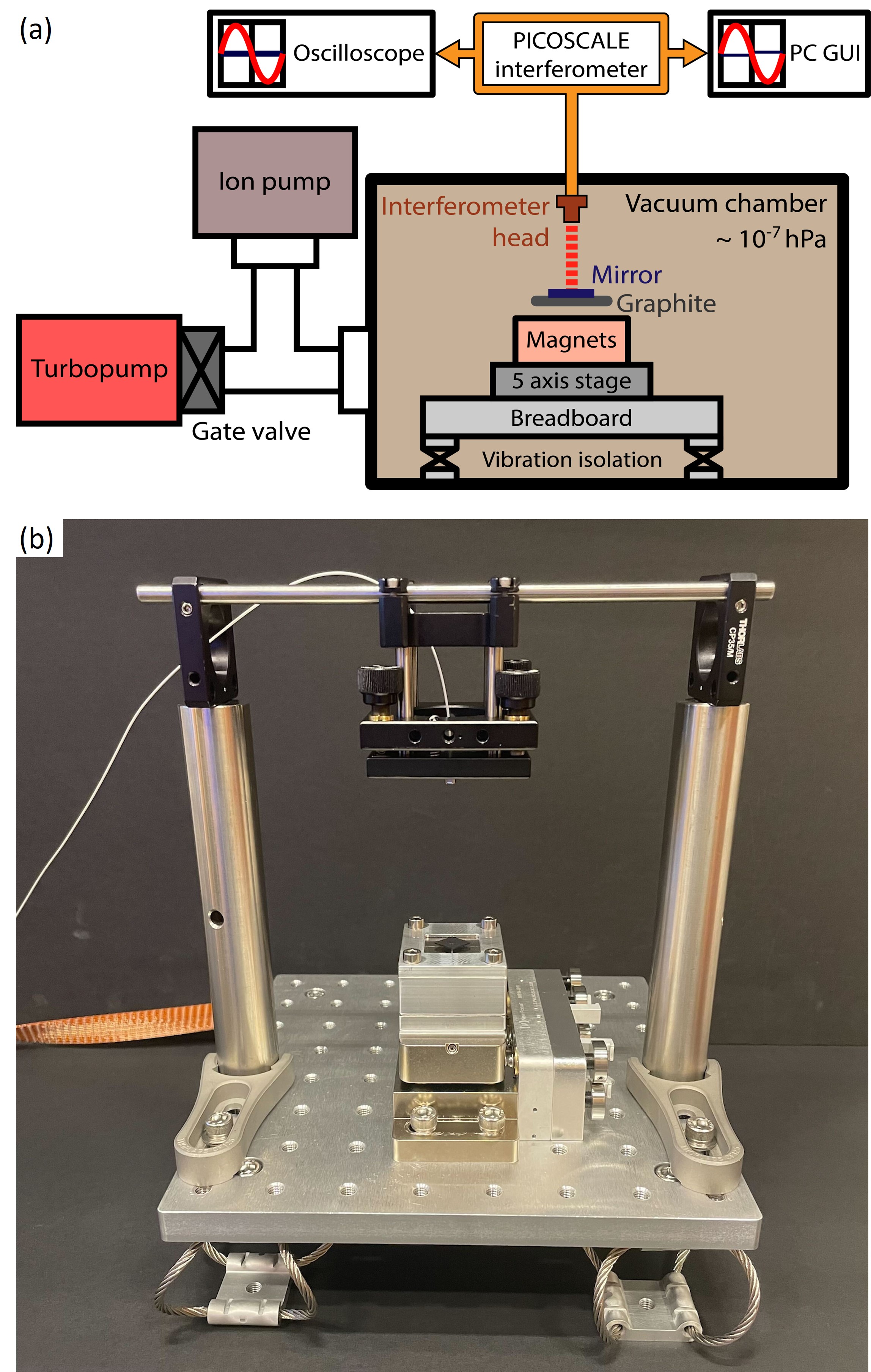
A sketch of the experimental setup is presented in Fig. 1. A plate of pyrolytic graphite is levitated by four NdFeB magnets placed in an alternating polarity checkerboard pattern. The magnets are rigidly held within a holder which is fixed to a five axis vacuum-compatible motorised stage. The magnet/motor platform is mounted on a small optical breadboard which in turn sits on four vibration isolation supports. The position of the graphite sample is monitored by an interferometric displacement sensor. This displacement sensor is based on a compact Michelson interferometer, and enables high precision measurements in real time with a resolution of picometers at a high bandwidth.
The whole structure is positioned in a vacuum chamber, which is evacuated by a system consisting of a turbopump, an ion pump, and associated roughing pump. During the measurement periods the turbopump is switched off to avoid unwanted mechanical vibrations, while the ion-pump operates continuously to maintain high vacuum (). The vacuum chamber and ion pump are supported by a damped and vibration isolated optical table, while the turbopump is supported by a separate vibration damped and isolated platform.
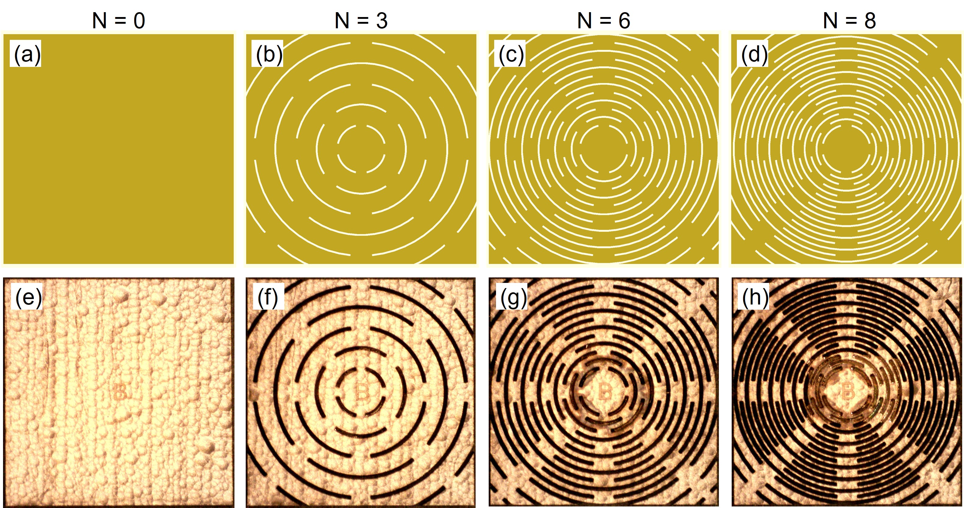
The experiment aims to increase the motional quality factor of a diamagnetically levitated slab of pyrolytic graphite. Four samples were machined from a single piece of graphite, to ensure they all possessed similar electric and magnetic properties. The thickness of each sample was approximately , however this was not uniform since the graphite surface was very coarse. Each plate had a pattern of ring-like slits machined into it whose purpose was to interrupt the eddy currents, and hence lower the resulting eddy damping forces. These slits were created by femtosecond laser machining. The slit designs, and photographs of the machined samples, are shown in Fig. 2. A small mirror was then glued onto the centre of each piece, to allow an interferometer to measure vertical displacement.
Each graphite sample was levitated for a period of twenty minutes, and its vertical position recorded using the interferometer. The resulting power spectral density was then analysed as described below. Further details of the setup are given in the Supplementary Material §1.
Due to its positioning, the interferometer is most sensitive to vertical motion of the plate. Using the normal mode simulation methods outlined above we find, and in agreement with Chen et al. [1], motion corresponding to three motional modes: vertical oscillation along the -axis, and torsion about the - and -axes. These are all expected to have frequencies of around 17Hz.
As the graphite plate moves, the magnetic field it experiences, and hence the magnitude and direction of the force on the plate, vary in a complex manner. This will cause a nontrivial coupling between all of the motional modes. For simplicity, we will approximate the three vertical modes as a single effective mode of a one-dimensional oscillator. This oscillator is primarily damped by eddy currents, induced by motion of the plate through the magnetic field. As we discuss in the Supplementary Material §3, damping due to air should be negligible at the pressures we consider.
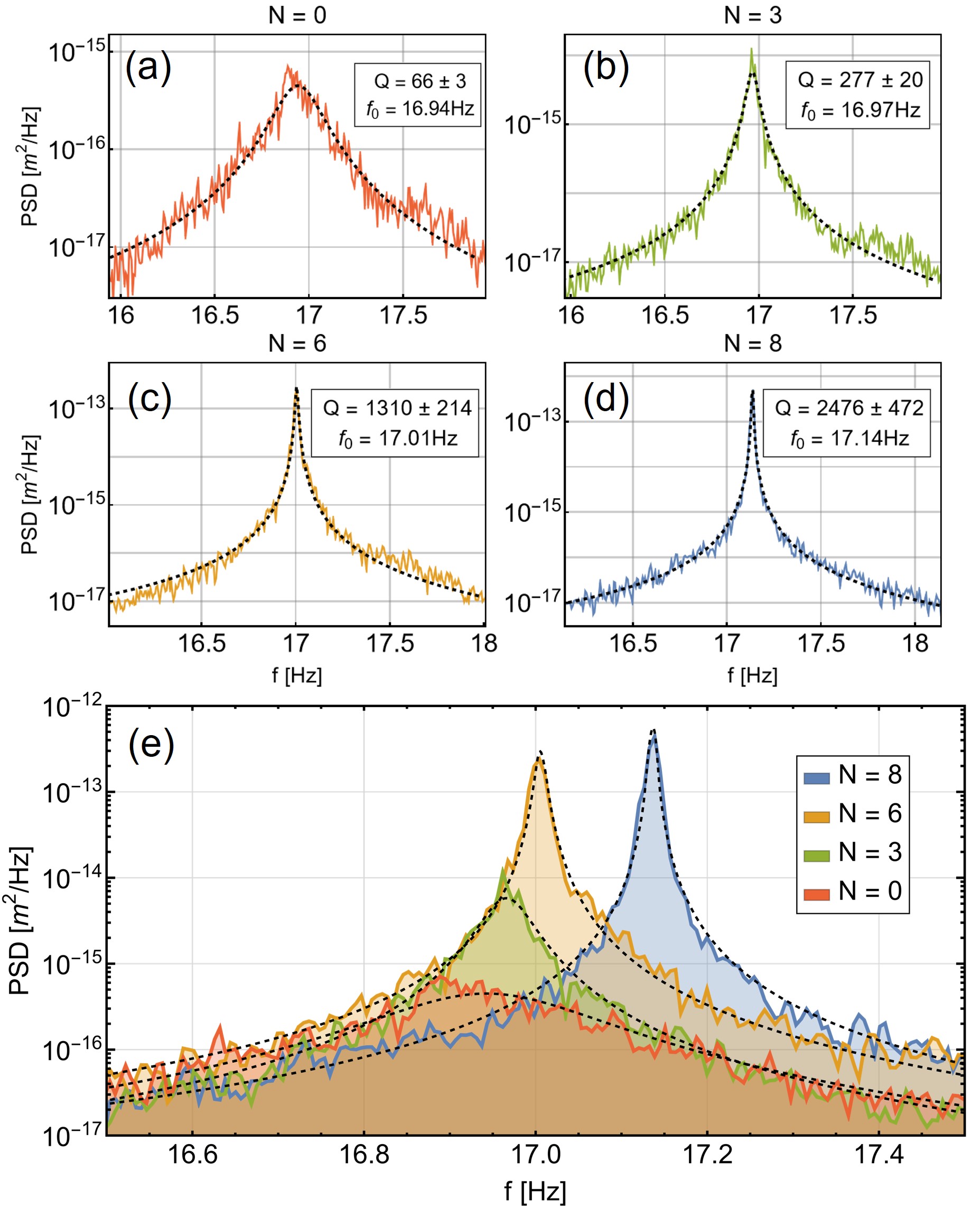
The power spectral density for a harmonic oscillator is given in §10 of Ref. 54, and discussed further in our Supplementary Material §3. The power spectral densities for the experimental data traces were fitted to the theoretical values, allowing us to extract the effective damping rates and natural frequencies , from which we could calculate the quality factor of each oscillator. These are shown in Fig. 3.
As expected, the oscillation frequencies were all approximately 17Hz. As the number of slots increases, there is a slight upwards shift in . This is most likely due to the slots removing material from the graphite plate, leading to a decrease in levitation height, and hence change in the magnetic trapping force. In total, the rings are able to increase the oscillator quality factor by a factor of approximately forty.
To understand the frequencies observed in the power spectral density, we simulated the motional modes for the plate. These modes are determined by the forces and torques experienced as it moves through the inhomogenous magnetic field above the magnet array. As discussed in the Supplementary Material §2, there are six modes in total. Three of them, oscillations in the horizontal plane or rotation about the vertical axis, have frequencies bunched around . The other three involve vertical motion, namely vertical oscillation and tilting about the horizontal axes, and are predicted to have frequencies around . It is these vertical modes that our interferometric setup will be most sensitive to.
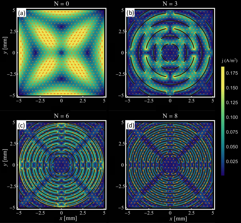
To estimate the increase in quality factor due to the slits, we simulated the eddy currents in each of the graphite plates in Fig. 2. The currents are induced by an effective electric potential which depends on the geometry of the plate and its motion through the external magnetic field [55, 56, 57, 1]. This current then exerts a force on the plate due to the magnetic field, which can be integrated to find the induced eddy damping. We developed both a two-dimensional model in Mathematica, and three-dimensional COMSOL simulation, the details of which are described in Supplementary Material §4.
The two-dimensional model used the finite element method in Mathematica 13.0 to simulate the currents. Moving from to , the total current was found to have decreased by an order of magnitude. Around the edges of a slit very large currents could occur, however as these occur in infinitesimal areas they do not contribute significantly to eddy damping.
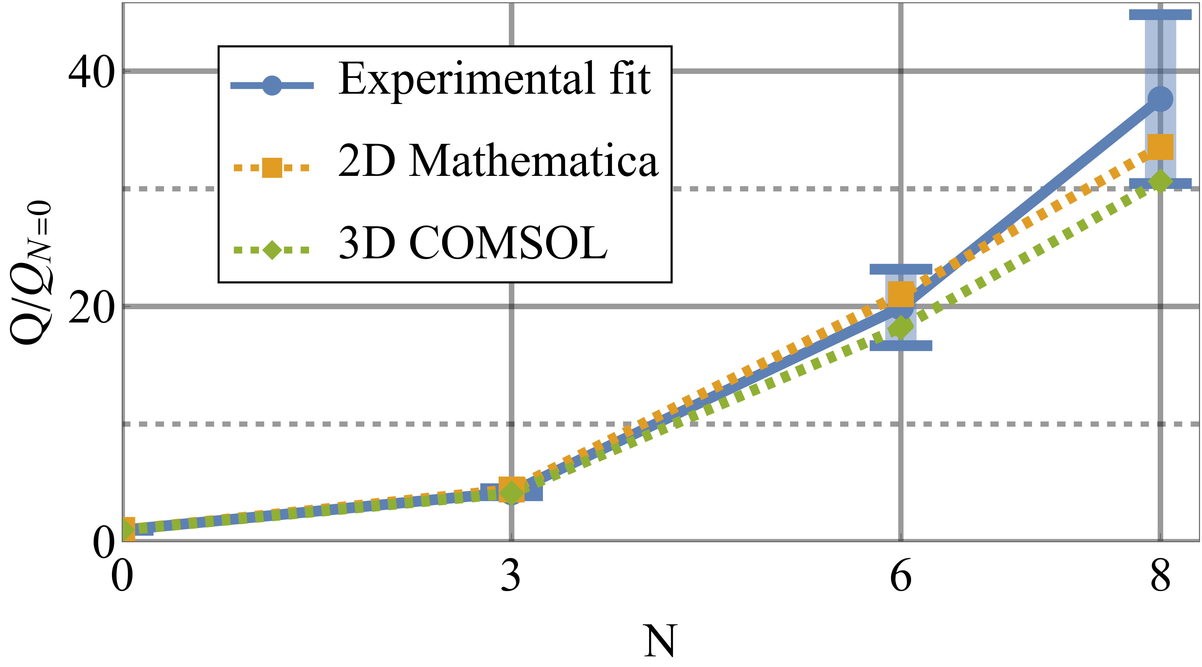
At low pressures, eddy currents are solely responsible for motional damping of the plate. The quality factor of a mode is inversely proportional to the damping rate: , for sample with mass . Hence we can predict the ratio of quality factors of the different plates, by calculating the ratios of their corresponding values and masses. These are shown in Fig. 4. We can see that the simulated values agree well with experiment. The sample does appear to have a slightly larger quality factor than predicted, which as we will discuss later is most likely due to the machined slots being wider than the design.
We also built a three-dimensional model using the commercial FEM package COMSOL. The eddy currents are plotted in Fig. 5 (these do not significantly differ from those generated in Mathematica). Using this we were able to predict the absolute values of the quality factors , rather than simply their ratios. The results of the COMSOL simulation are also plotted in Fig. 4, agreeing with the results from the experiment and Mathematica.
The motional quality factor of the graphite plates was measured to increase as more slots were cut into the surface. This increase was consistent with both the two-dimensional Mathematica and three-dimensional COMSOL simulations of the eddy current damping. This indicates that the increase in quality factor is indeed due to suppression of eddy currents. Overall currents were suppressed by an order of magnitude, corresponding to an increase in quality factor of forty.
In Fig. 4 we can see that for , the simulated quality factors are slightly lower than the experimental value. We attribute this primarily to a discrepancy between the designed slot patterns, and what is created by the femtosecond laser cutting. In Fig. 2, the slot patterns of the laser-cut samples are clearly wider than the CAD designs. Moreover, the machining process carves V-shaped slits which remove more graphite than expected, an effect which is is more pronounced at high slit density. Wider slots yield less eddy currents and thus reduced eddy damping, leading to higher quality factors in the actual samples than what is predicted by our models.
Graphite is one of the strongest diamagnetic materials known, and has great potential for use in levitated technologies. However, due to its high electrical conductivity it exhibits strong eddy damping. The ability to engineer this damping while retaining a strong diamagnetic susceptibility will permit researchers in a wide range of disciplines the ability to apply such conducting diamagnetic materials to situations where fast motional control is required. We show that by patterning the graphite plate with through-slots we can interrupt the eddy currents in a controlled manner, and gain detailed control over the eddy damping while retaining the strong diamagnetic lift. In this study we have not optimized the slotted pattern, and it is an interesting question whether one can produce designs which remove the least material, maintain the structural integrity of the plate, and control the eddy damping to the maximal extent.
Acknowledgements
This work was supported by the Okinawa Institute of Science and Technology Graduate University, Japan and Macquarie University, Sydney, Australia. The authors acknowledge technical assistance from E. Elerabi and P. Kennedy from the OIST Engineering Section. The graphite slab machining work was performed in part at the OptoFab node of the Australian National Fabrication Facility (ANFF) utilising Commonwealth and NSW State Government funding.
I Data Availability Statement
The data and simulation codes that support the findings of this study are available from the corresponding author upon reasonable request.
References
- Chen et al. [2020] X. Chen, A. Keşkekler, F. Alijani, and P. G. Steeneken, Rigid body dynamics of diamagnetically levitating graphite resonators, Applied Physics Letters 116, 243505 (2020).
- Berry and Geim [1997] M. V. Berry and A. K. Geim, Of flying frogs and levitrons, European Journal of Physics 18, 307 (1997).
- Simon and Geim [2000] M. D. Simon and A. K. Geim, Diamagnetic levitation: Flying frogs and floating magnets (invited), Journal of Applied Physics 87, 6200 (2000).
- Simon et al. [2001] M. D. Simon, L. O. Heflinger, and A. K. Geim, Diamagnetically stabilized magnet levitation, American Journal of Physics 69, 702 (2001).
- Gonzalez-Ballestero et al. [2021] C. Gonzalez-Ballestero, M. Aspelmeyer, L. Novotny, R. Quidant, and O. Romero-Isart, Levitodynamics: Levitation and control of microscopic objects in vacuum, Science 374, eabg3027 (2021).
- Gao et al. [2021] Q. Gao, H. Yan, H. Zou, W. Li, Z. Peng, G. Meng, and W. Zhang, Magnetic levitation using diamagnetism: Mechanism, applications and prospects, Science China Technological Sciences 64, 44 (2021).
- Gieseler and Millen [2018] J. Gieseler and J. Millen, Levitated Nanoparticles for Microscopic Thermodynamics—A Review, Entropy 20, 326 (2018).
- Pontin et al. [2020] A. Pontin, N. P. Bullier, M. Toroš, and P. F. Barker, Ultranarrow-linewidth levitated nano-oscillator for testing dissipative wave-function collapse, Physical Review Research 2, 023349 (2020).
- Moore and Geraci [2021] D. C. Moore and A. A. Geraci, Searching for new physics using optically levitated sensors, Quantum Science and Technology 6, 014008 (2021).
- Xiong et al. [2021] F. Xiong, T. Wu, Y. Leng, R. Li, C.-K. Duan, X. Kong, P. Huang, Z. Li, Y. Gao, X. Rong, and J. Du, Searching spin-mass interaction using a diamagnetic levitated magnetic-resonance force sensor, Physical Review Research 3, 013205 (2021).
- Timberlake et al. [2021] C. Timberlake, A. Vinante, F. Shankar, A. Lapi, and H. Ulbricht, Probing modified gravity with magnetically levitated resonators, Physical Review D 104, L101101 (2021).
- Bose et al. [2017] S. Bose, A. Mazumdar, G. W. Morley, H. Ulbricht, M. Toroš, M. Paternostro, A. A. Geraci, P. F. Barker, M. S. Kim, and G. Milburn, Spin Entanglement Witness for Quantum Gravity, Physical Review Letters 119, 240401 (2017).
- Marletto and Vedral [2017] C. Marletto and V. Vedral, Gravitationally Induced Entanglement between Two Massive Particles is Sufficient Evidence of Quantum Effects in Gravity, Physical Review Letters 119, 240402 (2017).
- Christodoulou and Rovelli [2019] M. Christodoulou and C. Rovelli, On the possibility of laboratory evidence for quantum superposition of geometries, Physics Letters, Section B: Nuclear, Elementary Particle and High-Energy Physics 792, 64 (2019).
- Carlesso et al. [2019] M. Carlesso, A. Bassi, M. Paternostro, and H. Ulbricht, Testing the gravitational field generated by a quantum superposition, New Journal of Physics 21, 093052 (2019).
- Nguyen and Bernards [2020] H. C. Nguyen and F. Bernards, Entanglement dynamics of two mesoscopic objects with gravitational interaction, European Physical Journal D 74, 2 (2020).
- Marshman et al. [2022] R. J. Marshman, A. Mazumdar, R. Folman, and S. Bose, Constructing nano-object quantum superpositions with a Stern-Gerlach interferometer, Physical Review Research 4, 023087 (2022).
- Garmire et al. [2007] D. Garmire, H. Choo, R. Kant, S. Govindjee, C. H. Séquin, R. S. Muller, and J. Demmel, Diamagnetically levitated MEMS accelerometers, in TRANSDUCERS and EUROSENSORS ’07 - 4th International Conference on Solid-State Sensors, Actuators and Microsystems (2007) pp. 1203–1206.
- Hempston et al. [2017] D. Hempston, J. Vovrosh, M. Toroš, G. Winstone, M. Rashid, and H. Ulbricht, Force sensing with an optically levitated charged nanoparticle, Applied Physics Letters 111, 133111 (2017).
- Prat-Camps et al. [2017] J. Prat-Camps, C. Teo, C. C. Rusconi, W. Wieczorek, and O. Romero-Isart, Ultrasensitive Inertial and Force Sensors with Diamagnetically Levitated Magnets, Physical Review Applied 8, 034002 (2017).
- Timberlake et al. [2019] C. Timberlake, G. Gasbarri, A. Vinante, A. Setter, and H. Ulbricht, Acceleration sensing with magnetically levitated oscillators above a superconductor, Applied Physics Letters 115, 224101 (2019).
- Monteiro et al. [2020] F. Monteiro, W. Li, G. Afek, C. L. Li, M. Mossman, and D. C. Moore, Force and acceleration sensing with optically levitated nanogram masses at microkelvin temperatures, Physical Review A 101, 53835 (2020).
- Lewandowski et al. [2021a] C. W. Lewandowski, T. D. Knowles, Z. B. Etienne, and B. D’Urso, High-Sensitivity Accelerometry with a Feedback-Cooled Magnetically Levitated Microsphere, Physical Review Applied 15, 014050 (2021a).
- Arvanitaki and Geraci [2013] A. Arvanitaki and A. A. Geraci, Detecting High-Frequency Gravitational Waves with Optically Levitated Sensors, Physical Review Letters 110, 071105 (2013).
- Yin et al. [2022] P. Yin, R. Li, C. Yin, X. Xu, X. Bian, H. Xie, C.-K. Duan, P. Huang, J.-h. He, and J. Du, Experiments with levitated force sensor challenge theories of dark energy, Nature Physics 10.1038/s41567-022-01706-9 (2022).
- Kumar and Bhattacharya [2017] P. Kumar and M. Bhattacharya, Magnetometry via spin-mechanical coupling in levitated optomechanics, Optics Express 25, 19568 (2017).
- Chen et al. [2021] X. Chen, N. Kothari, A. Keşkekler, P. G. Steeneken, and F. Alijani, Diamagnetically levitating resonant weighing scale, Sensors and Actuators A: Physical 330, 112842 (2021).
- Vaskuri et al. [2021] A. K. Vaskuri, D. W. Rahn, P. A. Williams, and J. H. Lehman, Absolute radiation pressure detector using a diamagnetically levitating test mass, Optica 8, 1380 (2021).
- Tebbenjohanns et al. [2020] F. Tebbenjohanns, M. Frimmer, V. Jain, D. Windey, and L. Novotny, Motional Sideband Asymmetry of a Nanoparticle Optically Levitated in Free Space, Physical Review Letters 124, 13603 (2020).
- Delić et al. [2020] U. Delić, M. Reisenbauer, K. Dare, D. Grass, V. Vuletić, N. Kiesel, and M. Aspelmeyer, Cooling of a levitated nanoparticle to the motional quantum ground state, Science 367, 892 (2020).
- Magrini et al. [2021] L. Magrini, P. Rosenzweig, C. Bach, A. Deutschmann-Olek, S. G. Hofer, S. Hong, N. Kiesel, A. Kugi, and M. Aspelmeyer, Real-time optimal quantum control of mechanical motion at room temperature, Nature 595, 373 (2021).
- Tebbenjohanns et al. [2021] F. Tebbenjohanns, M. L. Mattana, M. Rossi, M. Frimmer, and L. Novotny, Quantum control of a nanoparticle optically levitated in cryogenic free space, Nature 595, 378 (2021).
- Millen and Stickler [2020] J. Millen and B. A. Stickler, Quantum experiments with microscale particles, Contemporary Physics 61, 155 (2020).
- Pelrine et al. [2012] R. Pelrine, A. Wong-Foy, B. McCoy, D. Holeman, R. Mahoney, G. Myers, J. Herson, and T. Low, Diamagnetically levitated robots: An approach to massively parallel robotic systems with unusual motion properties, Proceedings - IEEE International Conference on Robotics and Automation , 739 (2012).
- Pelrine et al. [2016] R. Pelrine, A. Hsu, A. Wong-Foy, B. McCoy, and C. Cowan, Optimal control of diamagnetically levitated milli robots using automated search patterns, in 2016 International Conference on Manipulation, Automation and Robotics at Small Scales (MARSS) (IEEE, 2016) pp. 1–6.
- Hsu et al. [2017] A. Hsu, C. Cowan, W. Chu, B. McCoy, A. Wong-Foy, R. Pelrine, C. Velez, D. Arnold, J. Lake, J. Ballard, and J. Randall, Automated 2D micro-assembly using diamagnetically levitated milli-robots, in 2017 International Conference on Manipulation, Automation and Robotics at Small Scales (MARSS) (IEEE, 2017) pp. 1–6.
- Pelrine et al. [2019] R. Pelrine, A. Hsu, and A. Wong-Foy, Methods and Results for Rotation of Diamagnetic Robots Using Translational Designs, in 2019 International Conference on Manipulation, Automation and Robotics at Small Scales (MARSS) (IEEE, 2019) pp. 1–6.
- Kuthan et al. [2020] J. Kuthan, M. Jurik, M. Vitek, and F. Mach, Collective Planar Actuation of Miniature Magnetic Robots Towards Individual Robot Operation, in 2020 International Conference on Manipulation, Automation and Robotics at Small Scales (MARSS) (IEEE, 2020) pp. 1–6.
- Kobayashi and Abe [2012] M. Kobayashi and J. Abe, Optical motion control of maglev graphite, Journal of the American Chemical Society 134, 20593 (2012).
- Han et al. [2018] B. Han, Y.-L. Zhang, Q.-D. Chen, and H.-B. Sun, Carbon-Based Photothermal Actuators, Advanced Functional Materials 28, 1802235 (2018).
- Yang et al. [2019] M. Yang, Z. Yuan, J. Liu, Z. Fang, L. Fang, D. Yu, and Q. Li, Photoresponsive Actuators Built from Carbon-Based Soft Materials, Advanced Optical Materials 7, 1900069 (2019).
- Young et al. [2019] J. Young, H. Biggs, S. Yee, and H. Elbidweihy, Optical control and manipulation of diamagnetically levitated pyrolytic graphite, AIP Advances 9, 10.1063/1.5129886 (2019).
- Ewall-Wice et al. [2019] M. Ewall-Wice, S. Yee, K. DeLawder, S. R. Montgomery, P. J. Joyce, C. Brownell, and H. ElBidweihy, Optomechanical Actuation of Diamagnetically Levitated Pyrolytic Graphite, IEEE Transactions on Magnetics 55, 1 (2019).
- Kim et al. [2020] J. H. Kim, J. Pyo, and T. Kim, Highly Mobile Levitating Soft Actuator Driven by Multistimuli-Responses, Advanced Materials Interfaces 7, 2001051 (2020).
- Huang et al. [2021] Y. Huang, Q. Yu, C. Su, J. Jiang, N. Chen, and H. Shao, Light-Responsive Soft Actuators: Mechanism, Materials, Fabrication, and Applications, Actuators 10, 298 (2021).
- Yee et al. [2021] S. Yee, L. Oney, T. Cosby, D. P. Durkin, and H. ElBidweihy, Photothermal actuation of levitated pyrolytic graphite revised, APL Materials 9, 101107 (2021).
- Shen et al. [2022] S. Shen, L. Wu, S. Yang, Q. Yang, J.-T. Liu, and Z. Wu, Optical energy harvesting in vibrate maglev graphite, Carbon 187, 266 (2022).
- Vikrant and Jayanth [2022] K. S. Vikrant and G. R. Jayanth, Diamagnetically levitated nanopositioners with large-range and multiple degrees of freedom, Nature Communications 13, 3334 (2022).
- Lewandowski et al. [2021b] C. W. Lewandowski, T. D. Knowles, Z. B. Etienne, and B. D’Urso, High-Sensitivity Accelerometry with a Feedback-Cooled Magnetically Levitated Microsphere, Physical Review Applied 15, 10.1103/PhysRevApplied.15.014050 (2021b).
- Nakashima [2020] R. Nakashima, Diamagnetic levitation of a milligram-scale silica using permanent magnets for the use in a macroscopic quantum measurement, Physics Letters A 384, 126592 (2020).
- Leng et al. [2021] Y. Leng, R. Li, X. Kong, H. Xie, D. Zheng, P. Yin, F. Xiong, T. Wu, C.-K. Duan, Y. Du, Z.-q. Yin, P. Huang, and J. Du, Mechanical Dissipation Below 1 Hz with a Cryogenic Diamagnetic Levitated Micro-Oscillator, Physical Review Applied 15, 024061 (2021).
- Niu et al. [2018] C. Niu, F. Lin, Z. M. Wang, J. Bao, and J. Hu, Graphene levitation and orientation control using a magnetic field, Journal of Applied Physics 123, 044302 (2018).
- Chen et al. [2022] X. Chen, S. K. Ammu, K. Masania, P. G. Steeneken, and F. Alijani, Diamagnetic Composites for High-Q Levitating Resonators, Advanced Science 2203619, 2203619 (2022).
- Wang and Uhlenbeck [1945] M. C. Wang and G. E. Uhlenbeck, On the theory of the Brownian motion II, Reviews of modern physics 17, 323 (1945).
- Kirpo et al. [2010] M. Kirpo, T. Boeck, and A. Thess, Eddy-current braking of a translating solid bar by a magnetic dipole, Pamm 10, 513 (2010).
- Votyakov and Thess [2012] E. V. Votyakov and A. Thess, Interaction of a magnetic dipole with a slowly moving electrically conducting plate, Journal of Engineering Mathematics 77, 147 (2012).
- Carlstedt et al. [2014] M. Carlstedt, K. Porzig, M. Ziolkowski, R. P. Uhlig, H. Brauer, and H. Toepfer, Comparison of Lorentz force eddy current testing and common eddy current testing-measurements and simulations, Studies in Applied Electromagnetics and Mechanics 39, 218 (2014).