Levitated Optomechanics with Meta-Atoms
Abstract
We propose to introduce additional control in levitated optomechanics by trapping a meta-atom, i.e. a subwavelength and high-permittivity dielectric particle supporting Mie resonances. In particular, we theoretically demonstrate that optical levitation and center-of-mass ground-state cooling of silicon nanoparticles in vacuum is not only experimentally feasible but it offers enhanced performance over widely used silica particles, in terms of trap frequency, trap depth and optomechanical coupling rates. Moreover, we show that, by adjusting the detuning of the trapping laser with respect to the particle’s resonance, the sign of the polarizability becomes negative, enabling levitation in the minimum of laser intensity e.g. at the nodes of a standing wave. The latter opens the door to trapping nanoparticles in the optical near-field combining red and blue-detuned frequencies, in analogy to two-level atoms, which is of interest for generating strong coupling to photonic nanostructures and short-distance force sensing.
Optical trapping and motional control of polarizable sub-micron objects in vacuum has become a very active research field [1, 2]. Recently, the motion of an optically levitated silica nanoparticle has been cooled to the quantum ground state, either using passive feedback cooling via coherent scattering into a cavity [3, 4, 5], or via active feedback cooling [6, 7, 8] with shot-noise limited optical detection. In addition, the optical dipole-dipole interaction between two silica nanoparticles trapped in vacuum in two separate optical tweezers has been measured [9], which opens the door to study many-particle physics in vacuum [10, 11, 12, 13, 2, 14, 15, 16]. Optical trapping and control in vacuum of more complex particles supporting internal resonances has thus far been considered unattainable due to laser absorption, and have been solely studied by using low frequency electric [17, 18, 19, 20] or magnetic fields [21, 22, 23, 20, 24, 25, 26, 27, 28]. In contrast to optical manipulation, magnetic and electric platforms are less advanced and face additional challenges in terms of motional control in the quantum regime [2].
In this Letter, we analyze the use of Mie resonances supported by silicon nanoparticles [29] for optical levitation in vacuum [30]. We demonstrate that the resonances enable larger trap frequencies and trap depths compared to silica nanoparticles. Remarkably, we also evidence that silicon nanoparticles of few hundred nanometers behave, from the optomechanical standpoint, as a meta-atom whose polarizability changes sign across the resonance. In analogy with two-level atoms, this enables trapping the particle in regions of minimum laser intensity [31, 32, 33, 34]. The frequency-dependent sign of the polarizability is foreseen to enable trapping of silicon particles near a surface by using two-color near-field traps [35, 36]. The latter is of interest to couple particle’s motion to optical microcavities [37] or other integrated photonic systems [38, 39, 40]. In the context of optical interaction of many particles, optical resonances pave the way to engineer stronger and more complex types of interactions beyond dipole-dipole interaction. Last but not least, in the context of levitated optomechanics, we theoretically show how to achieve motional ground-state cooling of optically resonant nanoparticles and discuss its distinctive features, including larger cooling rates and even the possibility to enter the strong optomechanical coupling regime in free space [41, 42, 3].
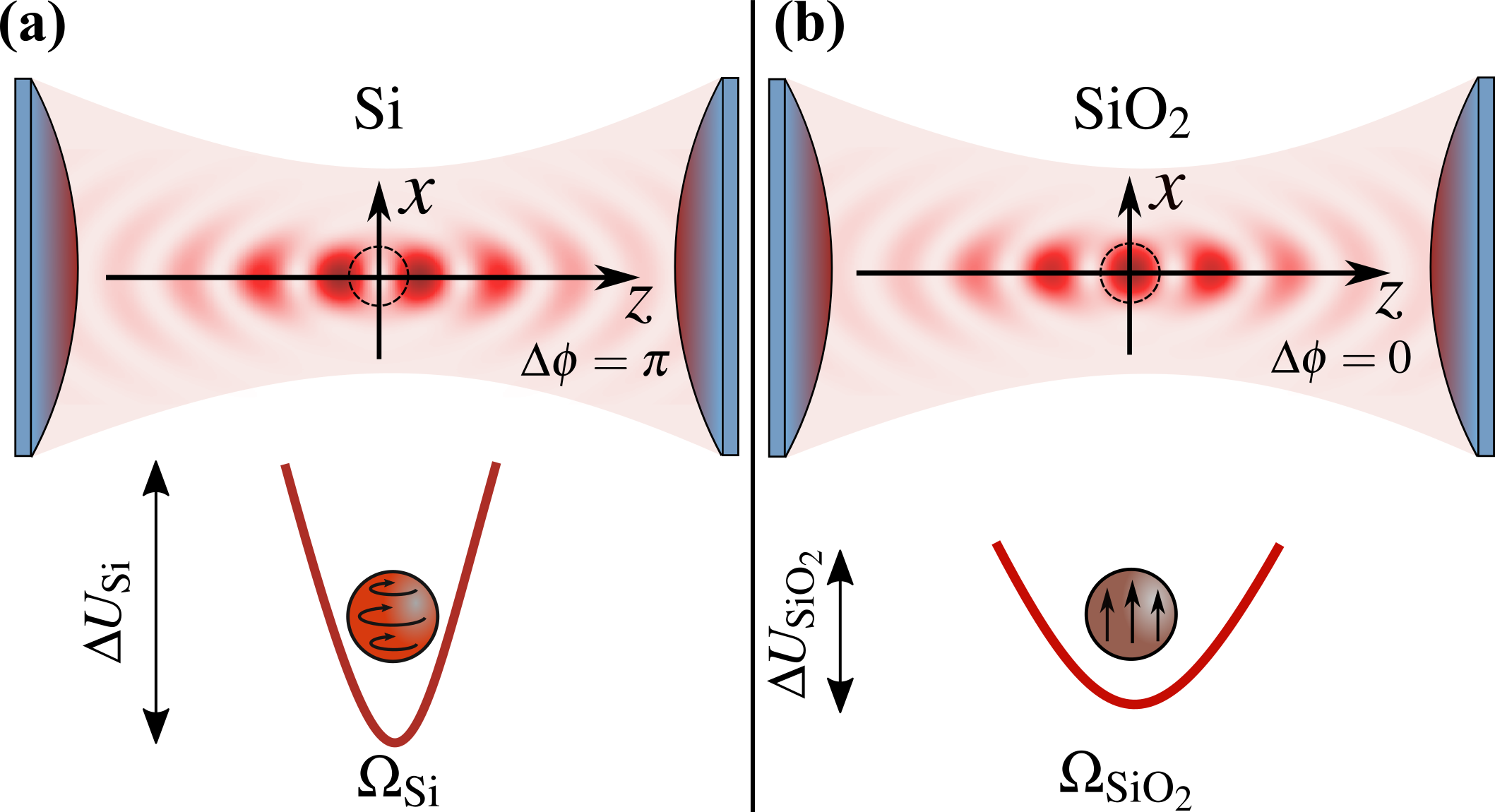
Let us consider a spherical silicon (Si) particle of radius , mass , and homogeneous refractive index , interacting with laser light in ultra-high vacuum. We consider a standing wave pattern along the -axis that is formed by two polarized and counter-propagating focused laser beams of equal wavelength , and with a relative phase [43, 44, 45, 46] (Fig. 1). The case and corresponds to the optical configuration with constructive interference and destructive interference at the focal point, respectively. Due to the symmetry of the illumination, the scattering forces experienced by the particle cancel out such that trapping conditions are fully determined by both field intensity gradients and particle polarizability. Unlike subwavelength silica (SiO2) nanoparticles that behave as non-resonant dipole scatterers, a subwavelength Si nanoparticle supports multipolar Mie resonances [29] whose spectral features depend on the real part of the dielectric constant and the ratio . The enhanced nanoparticle polarizability at a given Mie resonance is expected to substantially increase the total force experienced by the particle, and thereby to increase trap depth and trap frequencies compared to a SiO2 nanoparticle (Fig. 1). Furthermore, as discussed later, Mie resonances offer an opportunity to control the sign of the force by an appropriate detuning between the Mie resonance and the frequency of the trapping laser, thereby enabling to trap particles at a dark spot (Fig. 1a).
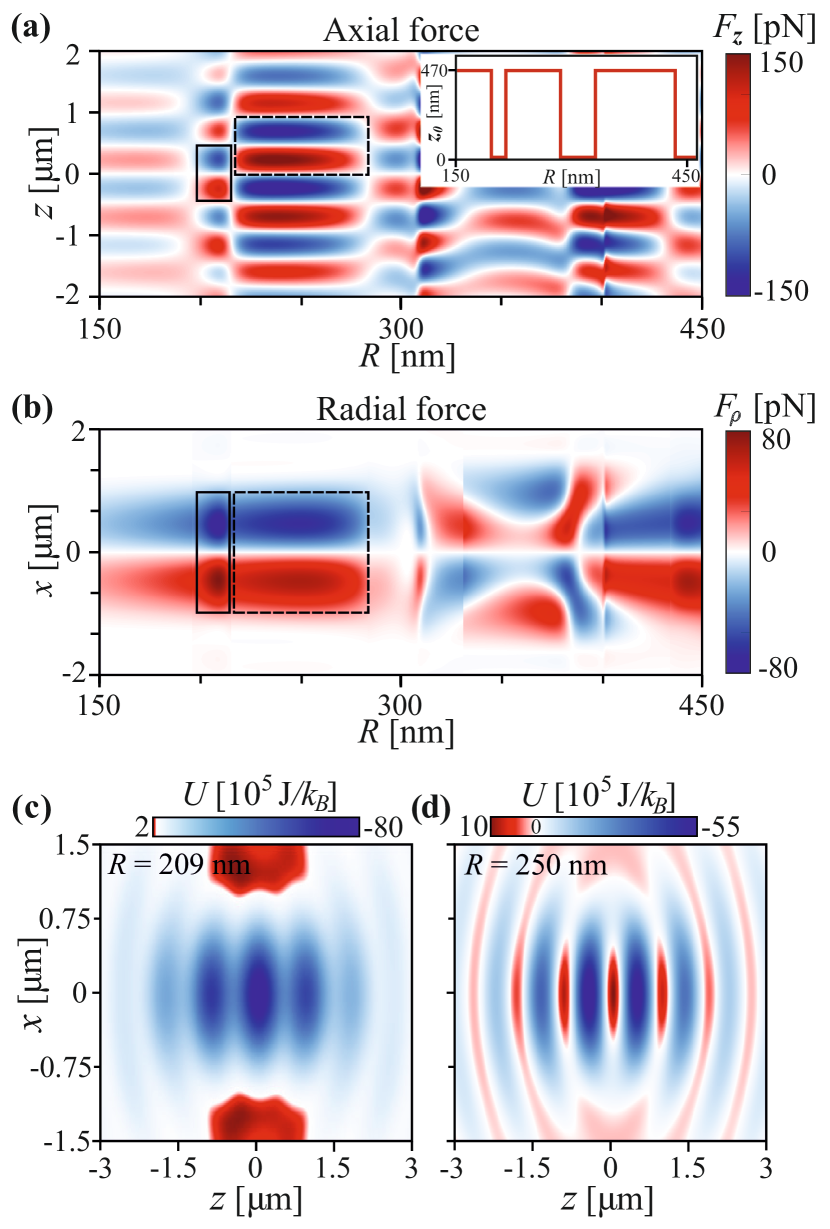
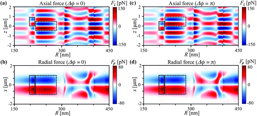
To test these hypotheses, we use the optical tweezers computational toolbox (OTT) [47] to calculate the total optical force on a Si nanoparticle with center-of-mass position in the standing-wave configuration described above. We set the focal point of the standing wave at (Fig. 1). Hereafter, we make use of the paraxial approximation such that the optical force acting on a particle placed near the focus has cylindrical symmetry [48]. Hence, the total force is characterized by a force term along the standing-wave axis, denoted by , and a force term perpendicular to the optical axis, denoted by . In Fig. 2a we plot as a function of radius and axial distance for (dark focal spot) and using the experimental parameters given in Table 1. Note that, changes its sign multiple times both as a function of due to the standing wave profile and, remarkably, as a function of radius as the trapping wavelength swipes across the different Mie resonances. Similar sign flips are observed for the radial force as a function of radius and radial distance , see Fig. 2b. For (bright focal spot) the axial force displays opposite attractive and repulsive regions while the radial force remains unchanged, see [49]. Overall three-dimensional trapping can be achieved in the dark, where, in absence of the particle, light destructively interferes. As seen from the map of the optical potential displayed in Fig. 2c and d, the axial trapping position occurs either at the focal dark point for radii in the range and in a neighbouring bright spot for radii in the range (these radii ranges are highlighted by the black boxes in Fig. 2a and b). Hereafter, we will exclusively consider optical trapping at the focal point , which requires using either (dark trapping) or (bright trapping) configuration depending on the particle size.
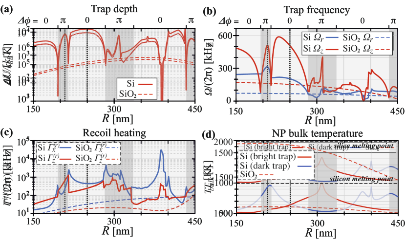
In particle trapping, both the trap depth and the trap frequencies and are key parameters to quantify the quality of the trap. The trap depth is defined as the kinetic motional energy required for the particle to escape. The trap frequencies and are defined when the optical potential is expanded around its minimum (in our case, near the focus), namely . In levitated optomechanics, the mechanical trap frequency along a given axis sets an important timescale for the dynamics. In the quantum regime, the trap frequency is required to be larger than the decoherence rate caused by any noise source other than laser recoil heating. Maximizing trap frequencies is thus desirable for bringing the motion of a particle into the quantum regime. In Fig. 3a we plot and in Fig. 3b and as a function of radius for a particle trapped at (the upper horizontal axis shows whether the dark or bright configuration is required). For comparison, we also display with the dashed line the case of a SiO2 nanoparticle for the bright configuration , which is the only possibility to trap a non-resonant dielectric particle. In contrast to what is observed for SiO2, and display for Si complex dependence with regions of both enhancement and diminution. The maximum trap depth is achieved for nm in the dark trapping and for nm in the bright trapping (black dotted lines), with trap depths approximately 25 times greater than for SiO2. Both axial and radial mechanical frequencies also display enhanced values, which can be more than 5 times larger than those of a SiO2 nanoparticle. Let us remark that the complex features of Fig. 3a and b correlate to the different electric and magnetic modes supported by the particle [50], as we show in [49].
| Parameters | Description |
|---|---|
| = 1550 nm | laser wavelength |
| P = 50 mW | laser power per beam |
| NA = 0.8 | numerical aperture |
| refractive index of Si [51] | |
| refractive index of Si [52] | |
| mass density of Si | |
| mass density of Si |
While so far we have focused on conservative dynamics, namely on the optical potential, the interaction of a dielectric particle with laser light also induces dissipative motional dynamics, i.e. laser light recoil heating [53, 54, 55]. Recoil heating induces a linear in time increase of center-of-mass energy due to the backaction caused by the scattered light that carries information about the center-of-mass position. The recoil heating rate along the axis () is defined as , where . The expected value represents an ensemble average over trajectories. In the context of quantum ground-state cooling of the center-of-mass motion of a dielectric particle via optical detection, recoil heating is of paramount importance. Fig. 3 shows for Si (solid) and SiO2 (dashed) particles as a function of radius calculated using recent theoretical methods [55]. We observe a complex behaviour for Si particles, while SiO2 shows smooth trends expected for particles in the Rayleigh regime. In general, for Si exceeds SiO2 for nearly all radii by up to 3 orders of magnitude. This increase is more pronounced for the axial direction. On one hand, higher leads to increased decoherence rates at equal power levels. On the other hand, this enhancement implies that more scattered photons carrying information about the particle position are collected, which is advantageous for active feedback cooling, as discussed below. Last but not least, we observe configurations in which is comparable or even larger than the trap frequencies, which is a signal of the strong optomechanical coupling regime. The possibility to enter and exploit the strong optomechanical regime in free space (i.e. without cavities) will be further investigated elsewhere.
Another critical parameter that determines the experimental feasibility of trapping in vacuum is the internal heating of the particle by laser absorption. Thus, it is important to estimate the particle’s internal temperature in the different optical trapping configurations under consideration. in high vacuum is estimated by balancing the absorbed laser power and the power emitted by the nanoparticle, which can be calculated using Mie solutions [56, 57, 58], see [49] for more details. In Fig. 3d, we show for a Si nanoparticle (solid) in the bright trapping (red) and dark trapping (blue) configuration as a function of radius for the experimental numbers given in Table 1. We observe three local maxima in of the Si nanoparticle that align with excited Mie resonances of a different order, see [49]. We notice that maximal values of coincide with increased . While Si nanoparticles heat up more (around a factor of 2) than SiO2 nanoparticles (dashed line), the internal temperature is lower than the melting point of bulk Si (K).
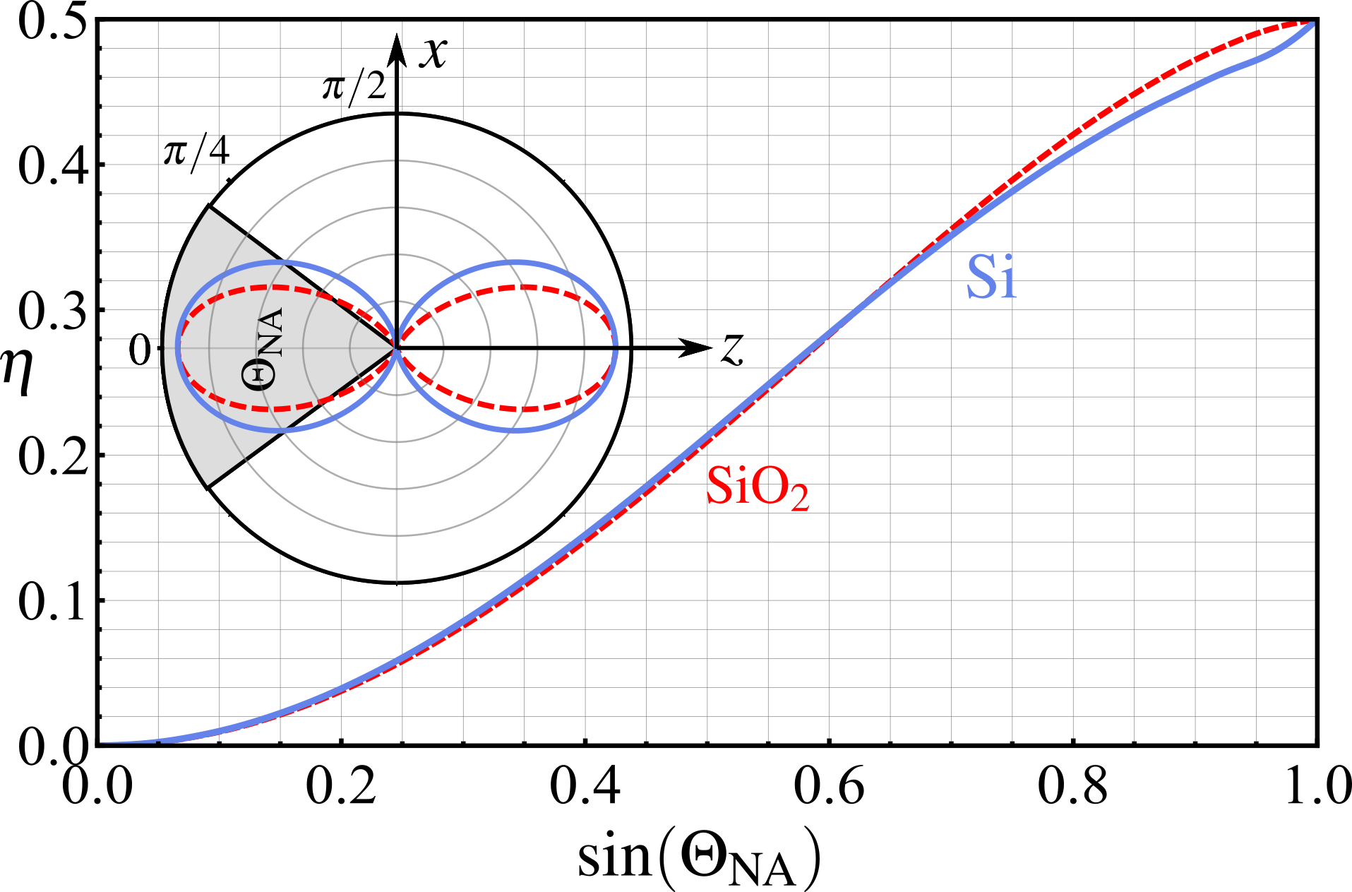
Let us now show that motional ground state cooling of a Si nanoparticle is experimentally feasible, especially in the dark trapping configuration. Assuming that laser recoil is the dominant source of motional heating, phonon occupation along a given axis, say the optical axis, , is only governed by the detection efficiency , with [59, 7, 6]. is the ratio of detected photons that are scattered from the particle by either increasing or decreasing the center-of-mass kinetic energy along the -axis. Hence, it is key to know the angular dependence of such scattered photons to evaluate the portion of them that can be detected and processed by the experimental configuration. This information is given by the so-called radiation patterns [59], calculated using recent theoretical methods [55]. Fig. S3 displays the radiation pattern associated with the motion along the -axis in the --plane for a Si nanoparticle in a dark (blue solid) and a SiO2 nanoparticle in a bright trap (red dashed), and equal radii . It illustrates that, under our conditions, scattered photons feature a very similar angular pattern. The grey shaded area illustrates the collected light fraction governed by the NA. For NA0.75, the reached detection efficiencies are equal for both scenarios, and for NA=0.8 the detection efficiency yields for Si and for . Hence, ground state cooling with is in reach, as already demonstrated for bright traps in [6, 7]. Let us emphasize that recoil heating for Si nanoparticles is up to 3 orders of magnitude larger than for SiO2 implying that ground-state cooling can be achieved either with 3 orders of magnitude faster time scale or with up to 3 orders of magnitude less laser power. In the regimes where the recoil heating rates are comparable or larger than the trapping frequencies, other cooling methods based on the use of light pulses could be employed [60].
In summary, we have shown how Mie resonances in silicon nanoparticles introduce an additional degree of control over the dynamics of levitated mechanical oscillators. First, the higher mechanical frequencies, trap depths, and recoil heating rates as compared to standard silica particles, contribute to increased motional quantum control of nanoparticles. Second, the sign change of the particle’s polarizability with the laser frequency enables trapping and center-of-mass ground-state cooling at a laser intensity minimum. We foresee that these unique properties of levitated meta-atoms will open new opportunities in levitodynamics [2], inspired by atom optics. In particular, multi-wavelength trapping should enable the accurate control of the distance to an interface [35], critical to the study of surface forces [61] and coupling to photonic structures [62]. Furthermore, parallel trapping of silicon meta-atoms, would allow the exploration of interactions beyond the dipole-dipole regime through higher order multipoles, such as electric or magnetic quadrupoles.
We acknowledge valuable discussions with Yuri Kivshar, Ivan Toftul and Massimiliano Rossi. S.L. acknowledges support of Priority 2030 Federal Academic Leadership Program. This research was supported by the European Research Council (ERC) under the grant Agreement No. [951234] (Q-Xtreme ERC-2020-SyG).
References
- Millen et al. [2020] J. Millen, T. S. Monteiro, R. Pettit, and A. N. Vamivakas, Optomechanics with levitated particles, Rep. Prog. Phys. 83, 026401 (2020).
- Gonzalez-Ballestero et al. [2021] C. Gonzalez-Ballestero, M. Aspelmeyer, L. Novotny, R. Quidant, and O. Romero-Isart, Levitodynamics: Levitation and control of microscopic objects in vacuum, Science 374 (2021).
- Delić et al. [2020] U. Delić, M. Reisenbauer, K. Dare, D. Grass, V. Vuletić, N. Kiesel, and M. Aspelmeyer, Cooling of a levitated nanoparticle to the motional quantum ground state, Science 367, 892 (2020).
- Ranfagni et al. [2022] A. Ranfagni, K. Børkje, F. Marino, and F. Marin, Two-dimensional quantum motion of a levitated nanosphere, Phys. Rev. Research 4, 033051 (2022).
- Piotrowski et al. [2023] J. Piotrowski, D. Windey, J. Vijayan, C. Gonzalez-Ballestero, A. de los Ríos Sommer, N. Meyer, R. Quidant, O. Romero-Isart, R. Reimann, and L. Novotny, Simultaneous ground-state cooling of two mechanical modes of a levitated nanoparticle, Nat. Phys. (2023).
- Tebbenjohanns et al. [2021] F. Tebbenjohanns, M. L. Mattana, M. Rossi, M. Frimmer, and L. Novotny, Quantum control of a nanoparticle optically levitated in cryogenic free space, Nature 595, 378 (2021).
- Magrini et al. [2021] L. Magrini, P. Rosenzweig, C. Bach, A. Deutschmann-Olek, S. G. Hofer, S. Hong, N. Kiesel, A. Kugi, and M. Aspelmeyer, Real-time optimal quantum control of mechanical motion at room temperature, Nature 595, 373 (2021).
- Kamba et al. [2022] M. Kamba, R. Shimizu, and K. Aikawa, Optical cold damping of neutral nanoparticles near the ground state in an optical lattice, Opt. Express 30, 26716 (2022).
- Rieser et al. [2022] J. Rieser, M. A. Ciampini, H. Rudolph, N. Kiesel, K. Hornberger, B. A. Stickler, M. Aspelmeyer, and U. Delić, Tunable light-induced dipole-dipole interaction between optically levitated nanoparticles, Science 377, 987 (2022).
- Burnham and McGloin [2006] D. R. Burnham and D. McGloin, Holographic optical trapping of aerosol droplets, Opt. Express 14, 4175 (2006).
- Dholakia and Zemánek [2010] K. Dholakia and P. Zemánek, Colloquium: Gripped by light: Optical binding, Rev. Mod. Phys. 82, 1767 (2010).
- Lechner et al. [2013] W. Lechner, S. J. M. Habraken, N. Kiesel, M. Aspelmeyer, and P. Zoller, Cavity optomechanics of levitated nanodumbbells: Nonequilibrium phases and self-assembly, Phys. Rev. Lett. 110, 143604 (2013).
- Liu et al. [2020] S. Liu, Z.-q. Yin, and T. Li, Prethermalization and nonreciprocal phonon transport in a levitated optomechanical array, Adv. Quantum Technol. 3, 1900099 (2020).
- Yan et al. [2022] J. Yan, X. Yu, Z. V. Han, T. Li, and J. Zhang, On-demand assembly of optically-levitated nanoparticle arrays in vacuum, arXiv:2207.03641 (2022).
- Verkerk et al. [1992] P. Verkerk, B. Lounis, C. Salomon, C. Cohen-Tannoudji, J.-Y. Courtois, and G. Grynberg, Dynamics and spatial order of cold cesium atoms in a periodic optical potential, Phys. Rev. Lett. 68, 3861 (1992).
- Jessen et al. [1992] P. S. Jessen, C. Gerz, P. D. Lett, W. D. Phillips, S. L. Rolston, R. J. C. Spreeuw, and C. I. Westbrook, Observation of quantized motion of rb atoms in an optical field, Phys. Rev. Lett. 69, 49 (1992).
- Fonseca et al. [2016] P. Fonseca, E. Aranas, J. Millen, T. Monteiro, and P. Barker, Nonlinear dynamics and strong cavity cooling of levitated nanoparticles, Phys. Rev. Lett. 117, 173602 (2016).
- Conangla et al. [2018] G. P. Conangla, A. W. Schell, R. A. Rica, and R. Quidant, Motion control and optical interrogation of a levitating single nitrogen vacancy in vacuum, Nano Letters 18, 3956 (2018).
- Conangla et al. [2020] G. P. Conangla, R. A. Rica, and R. Quidant, Extending vacuum trapping to absorbing objects with hybrid paul-optical traps, Nano Letters 20, 6018 (2020).
- Delord et al. [2020] T. Delord, P. Huillery, L. Nicolas, and G. Hétet, Spin-cooling of the motion of a trapped diamond, Nature 580, 56 (2020).
- Wang et al. [2019] T. Wang, S. Lourette, S. R. O’Kelley, M. Kayci, Y. Band, D. F. J. Kimball, A. O. Sushkov, and D. Budker, Dynamics of a ferromagnetic particle levitated over a superconductor, Phys. Rev. Appl. 11, 044041 (2019).
- Timberlake et al. [2019] C. Timberlake, G. Gasbarri, A. Vinante, A. Setter, and H. Ulbricht, Acceleration sensing with magnetically levitated oscillators above a superconductor, Appl. Phys. Lett. 115, 224101 (2019).
- Vinante et al. [2020] A. Vinante, P. Falferi, G. Gasbarri, A. Setter, C. Timberlake, and H. Ulbricht, Ultralow mechanical damping with meissner-levitated ferromagnetic microparticles, Phys. Rev. Appl. 13, 064027 (2020).
- Gieseler et al. [2020] J. Gieseler, A. Kabcenell, E. Rosenfeld, J. D. Schaefer, A. Safira, M. J. A. Schuetz, C. Gonzalez-Ballestero, C. C. Rusconi, O. Romero-Isart, and M. D. Lukin, Single-spin magnetomechanics with levitated micromagnets, Phys. Rev. Lett. 124, 163604 (2020).
- Lewandowski et al. [2021] C. W. Lewandowski, T. D. Knowles, Z. B. Etienne, and B. D’Urso, High-sensitivity accelerometry with a feedback-cooled magnetically levitated microsphere, Phys. Rev. Appl. 15, 014050 (2021).
- Latorre et al. [2022a] M. G. Latorre, A. Paradkar, D. Hambraeus, G. Higgins, and W. Wieczorek, A chip-based superconducting magnetic trap for levitating superconducting microparticles, IEEE Transactions on Applied Superconductivity 32, 1 (2022a).
- Latorre et al. [2022b] M. G. Latorre, G. Higgins, A. Paradkar, T. Bauch, and W. Wieczorek, Superconducting microsphere magnetically levitated in an anharmonic potential, arXiv:2210.13451 (2022b).
- Romero-Isart et al. [2012] O. Romero-Isart, L. Clemente, C. Navau, A. Sanchez, and J. I. Cirac, Quantum magnetomechanics with levitating superconducting microspheres, Phys. Rev. Lett. 109, 147205 (2012).
- Zhang et al. [2018] C. Zhang, Y. Xu, J. Liu, J. Li, J. Xiang, H. Li, J. Li, Q. Dai, S. Lan, and A. E. Miroshnichenko, Lighting up silicon nanoparticles with mie resonances, Nat. Comm. 9, 1 (2018).
- Ashkin and Dziedzic [1977] A. Ashkin and J. M. Dziedzic, Observation of resonances in the radiation pressure on dielectric spheres, Phys. Rev. Lett. 38, 1351 (1977).
- Grimm et al. [2000] R. Grimm, M. Weidemüller, and Y. B. Ovchinnikov, Optical Dipole Traps for Neutral Atoms, Advances In Atomic, Molecular, and Optical Physics, Vol. 42 (Academic Press, 2000) pp. 95–170.
- Kaplan et al. [2002] A. Kaplan, N. Friedman, and N. Davidson, Optimized single-beam dark optical trap, J. Opt. Soc. Am. B 19, 1233 (2002).
- Jaouadi et al. [2010] A. Jaouadi, N. Gaaloul, B. Viaris de Lesegno, M. Telmini, L. Pruvost, and E. Charron, Bose-einstein condensation in dark power-law laser traps, Phys. Rev. A 82, 023613 (2010).
- Juan et al. [2016] M. L. Juan, G. Molina-Terriza, T. Volz, and O. Romero-Isart, Near-field levitated quantum optomechanics with nanodiamonds, Phys. Rev. A 94, 023841 (2016).
- Le Kien et al. [2004] F. Le Kien, V. I. Balykin, and K. Hakuta, Atom trap and waveguide using a two-color evanescent light field around a subwavelength-diameter optical fiber, Phys. Rev. A 70, 063403 (2004).
- Vetsch et al. [2010] E. Vetsch, D. Reitz, G. Sagué, R. Schmidt, S. Dawkins, and A. Rauschenbeutel, Optical interface created by laser-cooled atoms trapped in the evanescent field surrounding an optical nanofiber, Phys. Rev. Lett. 104, 203603 (2010).
- Vahala [2003] K. J. Vahala, Optical microcavities, Nature 424, 839 (2003).
- Akahane et al. [2003] Y. Akahane, T. Asano, B.-S. Song, and S. Noda, High-q photonic nanocavity in a two-dimensional photonic crystal, Nature 425, 944 (2003).
- Deotare et al. [2009] P. B. Deotare, M. W. McCutcheon, I. W. Frank, M. Khan, and M. Lončar, High quality factor photonic crystal nanobeam cavities, Appl. Phys. Lett. 94, 121106 (2009).
- Magrini et al. [2018] L. Magrini, R. A. Norte, R. Riedinger, I. Marinković, D. Grass, U. Delić, S. Gröblacher, S. Hong, and M. Aspelmeyer, Near-field coupling of a levitated nanoparticle to a photonic crystal cavity, Optica 5, 1597 (2018).
- Ranfagni et al. [2021] A. Ranfagni, P. Vezio, M. Calamai, A. Chowdhury, F. Marino, and F. Marin, Vectorial polaritons in the quantum motion of a levitated nanosphere, Nature Physics 17, 1120 (2021).
- de los Ríos Sommer et al. [2021] A. de los Ríos Sommer, N. Meyer, and R. Quidant, Strong optomechanical coupling at room temperature by coherent scattering, Nat. Commun. 12, 1 (2021).
- Čižmár et al. [2005] T. Čižmár, V. Garcés-Chávez, K. Dholakia, and P. Zemánek, Optical conveyor belt for delivery of submicron objects, Appl. Phys. Lett. 86, 174101 (2005).
- Brzobohatỳ et al. [2013] O. Brzobohatỳ, V. Karásek, M. Šiler, L. Chvátal, T. Čižmár, and P. Zemánek, Experimental demonstration of optical transport, sorting and self-arrangement using a ‘tractor beam’, Nature Photonics 7, 123 (2013).
- Grass et al. [2016] D. Grass, J. Fesel, S. G. Hofer, N. Kiesel, and M. Aspelmeyer, Optical trapping and control of nanoparticles inside evacuated hollow core photonic crystal fibers, Appl. Phys. Lett. 108, 221103 (2016).
- Nikkhou et al. [2021] M. Nikkhou, Y. Hu, J. A. Sabin, and J. Millen, Direct and clean loading of nanoparticles into optical traps at millibar pressures, Photonics 8, 458 (2021).
- Nieminen et al. [2007] T. A. Nieminen, V. L. Loke, A. B. Stilgoe, G. Knöner, A. M. Brańczyk, N. R. Heckenberg, and H. Rubinsztein-Dunlop, Optical tweezers computational toolbox, J. Opt. A: Pure Appl. Opt. 9, S196 (2007).
- Novotny and Hecht [2012] L. Novotny and B. Hecht, Principles of nano-optics (Cambridge university press, 2012).
- [49] Supplementary material, which includes the references [63, 64, 65, 66, 67].
- Kivshar and Miroshnichenko [2017] Y. Kivshar and A. Miroshnichenko, Meta-optics with mie resonances, Optics and Photonics News 28, 24 (2017).
- Degallaix et al. [2013] J. Degallaix, R. Flaminio, D. Forest, M. Granata, C. Michel, L. Pinard, T. Bertrand, and G. Cagnoli, Bulk optical absorption of high resistivity silicon at 1550 nm, Opt. Lett. 38, 2047 (2013).
- Palik [1998] E. D. Palik, Handbook of optical constants of solids, Vol. 3 (Academic press, 1998).
- Jain et al. [2016] V. Jain, J. Gieseler, C. Moritz, C. Dellago, R. Quidant, and L. Novotny, Direct measurement of photon recoil from a levitated nanoparticle, Phys. Rev. Lett. 116, 243601 (2016).
- Gonzalez-Ballestero et al. [2019] C. Gonzalez-Ballestero, P. Maurer, D. Windey, L. Novotny, R. Reimann, and O. Romero-Isart, Theory for cavity cooling of levitated nanoparticles via coherent scattering: master equation approach, Phys. Rev. A 100, 013805 (2019).
- Maurer et al. [2022] P. Maurer, C. Gonzalez-Ballestero, and O. Romero-Isart, Quantum Theory of Light Interaction with a Dielectric Sphere: Towards 3D Ground-State Cooling, arXiv.2212.04838 (2022).
- Bohren and Huffman [2008] C. F. Bohren and D. R. Huffman, Absorption and scattering of light by small particles (John Wiley & Sons, 2008).
- Landström and Heszler [2004] L. Landström and P. Heszler, Analysis of blackbody-like radiation from laser-heated gas-phase tungsten nanoparticles, J. Phys. Chem. B 108, 6216 (2004).
- Bateman et al. [2014] J. Bateman, S. Nimmrichter, K. Hornberger, and H. Ulbricht, Near-field interferometry of a free-falling nanoparticle from a point-like source, Nat. Commun. 5, 1 (2014).
- Tebbenjohanns et al. [2019] F. Tebbenjohanns, M. Frimmer, and L. Novotny, Optimal position detection of a dipolar scatterer in a focused field, Phys. Rev. A 100, 043821 (2019).
- Bennett et al. [2016] J. S. Bennett, K. Khosla, L. S. Madsen, M. R. Vanner, H. Rubinsztein-Dunlop, and W. P. Bowen, A quantum optomechanical interface beyond the resolved sideband limit, New Journal of Physics 18, 053030 (2016).
- Geraci et al. [2010] A. A. Geraci, S. B. Papp, and J. Kitching, Short-range force detection using optically cooled levitated microspheres, Phys. Rev. Lett. 105, 101101 (2010).
- Forn-Díaz et al. [2019] P. Forn-Díaz, L. Lamata, E. Rico, J. Kono, and E. Solano, Ultrastrong coupling regimes of light-matter interaction, Rev. Mod. Phys. 91, 025005 (2019).
- Chen et al. [2011] J. Chen, J. Ng, Z. Lin, and C. T. Chan, Optical pulling force, Nat. Photonics 5, 531 (2011).
- Evlyukhin et al. [2016] A. B. Evlyukhin, T. Fischer, C. Reinhardt, and B. N. Chichkov, Optical theorem and multipole scattering of light by arbitrarily shaped nanoparticles, Phys. Rev. B 94, 205434 (2016).
- Farsund and Felderhof [1996] Ø. Farsund and B. Felderhof, Force, torque, and absorbed energy for a body of arbitrary shape and constitution in an electromagnetic radiation field, Phys. A: Stat. Mech. Appl. 227, 108 (1996).
- Schinke et al. [2015] C. Schinke, P. Christian Peest, J. Schmidt, R. Brendel, K. Bothe, M. R. Vogt, I. Kröger, S. Winter, A. Schirmacher, S. Lim, et al., Uncertainty analysis for the coefficient of band-to-band absorption of crystalline silicon, AIP Adv. 5, 067168 (2015).
- Chandler-Horowitz and Amirtharaj [2005] D. Chandler-Horowitz and P. M. Amirtharaj, High-accuracy, midinfrared ( ) refractive index values of silicon, J. Appl. Phys. 97, 123526 (2005).
Supplemental material
In section S1 of this supplementary material we show the intensity distributions of the two optical configurations we consider in the manuscript, showing both intensity maxima and minima at the trap origin. In section S2 we summarize the results on the total optical force for both optical configurations. In section S3 we discuss the link between the total effective polarizability influenced by Mie resonances and the optical force. In section S4 we examine the scattering and absorption cross sections of the nanoparticle. Finally, in section S5 we discuss the derivation of the internal temperature of the nanoparticle.
S1 Intensity profiles
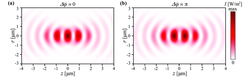
We consider two coherent, counter-propagating Gaussian beams of total power mW, laser wavelength nm and same transverse polarization. Each beam is focused along the optical axis by a high numerical aperture lens (NA=0.8) such that their two foci coincide and form a standing wave interference pattern with multiple intensity maxima and minima as depicted in Fig. S1. For a controlled phase difference between the two beams of (), an intensity maximum (minimum) forms at the origin .
S2 Exerted forces
We calculate the total optical force acting on the Si nanoparticle with the optical tweezers computational toolbox (OTT) [1]. The toolbox expands the Gaussian beam into the spherical harmonic basis and calculates the electric and magnetic fields scattered by the nanoparticle using Mie theory. Taking into account the incident and scattered light fields, is calculated via the Maxwell stress tensor approach. For the complex refractive index of Si at nm we consider [2] and interpolate for SiO2 [3].
Hereby, we consider two different trapping scenarios: First, an intensity maximum at the origin for (see Fig. S1a) giving rise to the optical forces displayed in Fig. S2a and b, and an intensity minimum at the origin for (see Fig. S1b) with optical forces as depicted in Fig. S2c and d. The axial force displays in both cases frequent sign changes with and . For the two different we find forces of opposite sign, as can be seen in Fig. S2a and c. This enables a dark trap center at the origin for . The radial force shows a similar frequent sign change with , but the force direction is the same for both . Due to the absence of interference in the radial direction, we observe at most one trap centre at ; except for radii in the range , where MR give rise to additional trap centers at . We attribute this effect to the interplay of several mulitpole MR at these particle sizes (see Fig. S3a). We extract as shown in Fig. 3a in the main text from the potential energy , where is the coordinate of the point where the potential is evaluated.
S3 Influence of the effective polarizability on trap characteristics
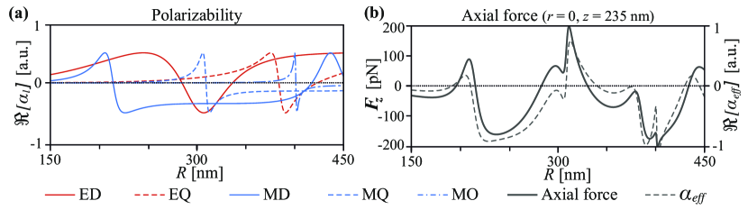
As pointed out in the manuscript, we attribute the modifications of , , , and at certain to the excitation of optical MR. We calculate polarizabilities associated with excitation of the MR of different order (corresponding to different electric and magnetic multipolar contributions) [4, 5]. The real part of those multipole polarizabilities are depicted in Fig. S3a. Here, MD (ED) is the magnetic (electric) dipole, MQ (EQ) is the magnetic (electric) quadrupole, and MO is the magnetic octupole. Note that the real part of the multipole polarizabilities is proportional to the imaginary part of the Mie scattering coefficients [5]. It is well-known that in the simplified dipole approximation, is proportional to . By cancelling the scattering force in counter-propagating beams, we suggest that the gradient force of is proportional to the real part of an effective polarizability which can be presented as a linear combination of multipole polarizabilities . To support our hypothesis, we approximate by a linear combination of [4] such that it fits the axial force , namely
| (S1) |
In Fig. S3b, we plot for as a function of the radius at the specific point , where reaches the maximum value (see Fig. S2a). Comparing (black solid) with (black dashed) in Fig. S3b, we find qualitative agreement in their behaviour with , enabling us to link qualitatively certain MR to optical force modifications. The discrepancies between (Fig. S3b, black solid) and (Fig. S3b, black dashed) are caused by the fact that the scattered electric field expanded into a series of contributes quadratically to [6], and the linear combination gives a limited approximation. For , the dominant terms are the ED (solid red curve), MD (solid blue curve), EQ (dashed red curve), MQ (dashed blue curve) and MO (dash dotted blue curve).
S4 Scattering and absorption cross section
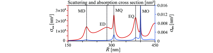
In Fig. S4 we show the scattering cross section and absorption cross section for a single plane wave propagating along the axis as a function of the nanoparticle radius . We observe that the cross section shares many features with in Fig. S3. The dashed lines highlight the individual MR. In particular, we recognize resonances at nm, nm, nm, nm and nm, where MD (ED) is the magnetic (electric) dipole, MQ (EQ) the magnetic (electric) quadrupole and MO the magnetic octupole. The absorption cross section is calculated using Mie theory as the difference between extinction cross section and scattering cross section [7], where
| (S2) | |||||
| (S3) |
and where is the wavenumber, and is the order of the electric and magnetic Mie coefficients [7].
S5 Nanoparticle internal temperature calculation
We determine the steady-state internal temperature of a nanoparticle in the laser field by minimizing the difference of absorbed laser power and the power emitted by the nanoparticle, that is
| (S4) |
where is the absorbed laser power, is the power spectral density of the absorbed environmental black body radiation at room temperature responsible for the nanoparticle heating and is the power spectral density of the nanoparticle emitted black body radiation responsible for cooling. The absorbed laser power is calculated by means of the optical tweezer toolbox (OTT) as the difference between the power leaving the system and the incident laser power . The incident power is equal to the power of the incoming co-polarized beams and expressed only through the incident electromagnetic field as mW. Here, the integration is taken on the plane perpendicular to the propagation directions. The outgoing power is obtained from the total field, i.e. a superposition of incident and scattered fields, and reads . The integration is performed on the closed surface surrounding the nanoparticle. The nanoparticle is placed at the origin (), and the phase difference between the counter-propagating of the beams takes on the values of and giving rise to the bright and dark trapping (Fig. S1a and b) respectively. The power spectral density of the black body radiation reads
| (S5) |
where denotes the speed of light in vacuum and denotes the Boltzmann constant. The absorption cross section depends on the complex refractive index of the nanoparticle. Thus becomes refractive index-dependent across the entire spectrum of the black body radiation. For the Si nanoparticle, we merge the refractive index spectra from Refs. [2, 8, 9], and for the SiO2 nanoparticle, we use the interpolated data from Ref. [3].
S6 Trap characterization for silicon and silica nanoparticles at identical recoil heating rates
In the following, we compare the trap performance when the recoil heating rates and experienced by Si and SiO2 nanoparticles are equal. We discussed in Fig. 3(c) of the main manuscript assuming W. Since and [10], we find overall that . This expression allows us to extract required to balance the recoil heating rates as .
Let us consider the dark (bright) trapping performance with nm ( nm) in the and direction. For nm, the respective recoil heating rates are equal at W and W, whereas for nm this happens at W and W. For all cases, exceeds W by orders of magnitude. For the following analysis, we select W.
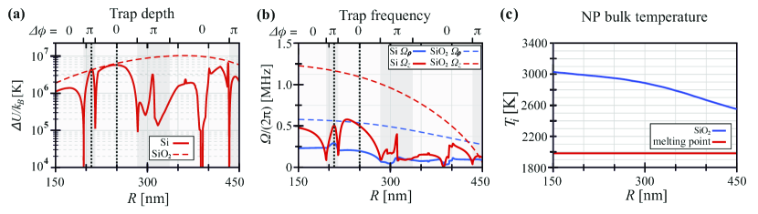
Figure S5 shows the trap depth , trap frequency and internal temperature as a function of . for each counter-propagating beam is fixed at 0.05 W and 2.7 W for Si and SiO2, respectively. Other parameters of the system remain the same as in the manuscript. Clearly, increasing raises both and of SiO2 to values significantly higher than those of Si (Figure S5(a,b)). However, of the SiO2 nanoparticle increases much beyond the melting point for such a high laser power. Note that, our internal temperature calculations consider only the linear optical losses of silica, disregarding the losses caused by optical non-linearities that arise at such high laser power levels.
References
- Nieminen et al. [2007] T. A. Nieminen, V. L. Loke, A. B. Stilgoe, G. Knöner, A. M. Brańczyk, N. R. Heckenberg, and H. Rubinsztein-Dunlop, J. Opt. A: Pure Appl. Opt. 9, S196 (2007).
- Degallaix et al. [2013] J. Degallaix, R. Flaminio, D. Forest, M. Granata, C. Michel, L. Pinard, T. Bertrand, and G. Cagnoli, Opt. Lett. 38, 2047 (2013).
- Palik [1998] E. D. Palik, Handbook of optical constants of solids, Vol. 3 (Academic press, 1998).
- Chen et al. [2011] J. Chen, J. Ng, Z. Lin, and C. T. Chan, Nat. Photonics 5, 531 (2011).
- Evlyukhin et al. [2016] A. B. Evlyukhin, T. Fischer, C. Reinhardt, and B. N. Chichkov, Phys. Rev. B 94, 205434 (2016).
- Farsund and Felderhof [1996] Ø. Farsund and B. Felderhof, Phys. A: Stat. Mech. Appl. 227, 108 (1996).
- Bohren and Huffman [2008] C. F. Bohren and D. R. Huffman, Absorption and scattering of light by small particles (John Wiley & Sons, 2008).
- Schinke et al. [2015] C. Schinke, P. Christian Peest, J. Schmidt, R. Brendel, K. Bothe, M. R. Vogt, I. Kröger, S. Winter, A. Schirmacher, S. Lim, et al., AIP Adv. 5, 067168 (2015).
- Chandler-Horowitz and Amirtharaj [2005] D. Chandler-Horowitz and P. M. Amirtharaj, J. Appl. Phys. 97, 123526 (2005).
- Gonzalez-Ballestero et al. [2019] C. Gonzalez-Ballestero, P. Maurer, D. Windey, L. Novotny, R. Reimann, and O. Romero-Isart, Phys. Rev. A 100, 013805 (2019).