Cloaking a qubit in a cavity
Abstract
Cavity quantum electrodynamics (QED) uses a cavity to engineer the mode structure of the vacuum electromagnetic field such as to enhance the interaction between light and matter. Exploiting these ideas in solid-state systems has lead to circuit QED which has emerged as a valuable tool to explore the rich physics of quantum optics and as a platform for quantum computation. Here we introduce a simple approach to further engineer the light-matter interaction in a driven cavity by controllably decoupling a qubit from the cavity’s photon population, effectively cloaking the qubit from the cavity. This is realized by driving the qubit with an external tone tailored to destructively interfere with the cavity field, leaving the qubit to interact with a cavity which appears to be in the vacuum state. Our experiment demonstrates how qubit cloaking can be exploited to cancel the ac-Stark shift and measurement-induced dephasing, and to accelerate qubit readout. In addition to qubit readout, applications of this method include qubit logical operations and the preparation of non-classical cavity states in circuit QED and other cavity-based setups.
Introduction
Cavity and circuit QED explore light-matter interaction at its most fundamental level, providing the tools to control the dynamical evolution of single atoms and photons in a deterministic fashion [1]. This has allowed circuit QED to emerge as a platform to explore the rich physics of quantum optics in novel parameter regimes and to become a leading architecture for quantum computing [2]. In this system, strong drives on the cavity are used to realize multi-qubit gates [3, 4], to stabilize quantum states of the cavity [5, 6, 7, 8], and for qubit readout [9, 2]. However, even under moderate cavity photon populations, cavity drives often lead to undesired effects such as qubit transitions [10] resulting in reduced readout fidelity [11], increased dephasing [4, 7], and imperfect quantum state stabilization [5, 6, 8]. Other consequences of cavity drives in the dispersive qubit-cavity regime are the qubit ac-Stark shift, which can result in unwanted phase accumulations [12], measurement-induced dephasing [13, 14], and Kerr nonlinearity [15].
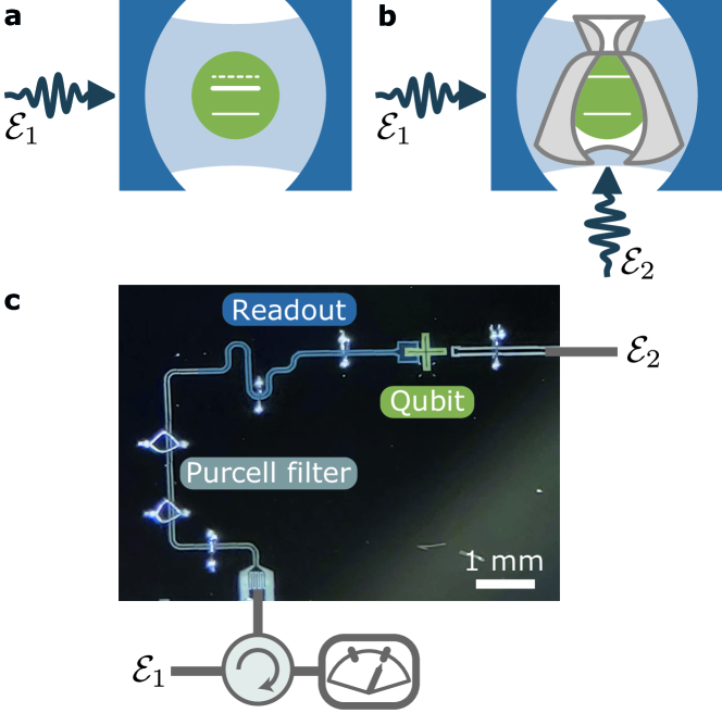
In this work, we introduce a simple approach to engineer light-matter interaction in a driven cavity and prevent some of these unwanted effects. We show how an appropriately tailored drive on the qubit can decouple the qubit state and the cavity’s photon population from one another, resulting in both systems interacting only through vacuum fluctuations of the cavity field. This qubit cloaking mechanism can be exploited to prepare non-classical states of the cavity field. Moreover, in the dispersive qubit-cavity regime, it results in the absence of ac-Stark shift and measurement-induced dephasing. This observation can be used to apply logical operations on the qubit in the presence of a cavity photon population, something which we exploit to accelerate qubit readout. Here, we experimentally demonstrate qubit cloaking using a transmon qubit [16] coupled to a coplanar waveguide resonator (Fig. 1.c).
Results
When loaded with a coherent state, the cavity field acts as an effective classical drive on the qubit. A simple intuition behind qubit cloaking is that an additional drive on the qubit can be designed to interfere destructively with this effective drive, resulting in an empty cavity from the perspective of the qubit. As an illustration of this concept, consider a transmon qubit coupled to a microwave cavity, see Fig. 1a,b for a schematic representation. Without driving, the system Hamiltonian reads [2]
| (1) |
with and the transmon charge and phase operators, the charging energy, the Josephson energy, the annihilation (creation) operator of the cavity mode of frequency , and the transverse coupling rate. The cavity drive is , where is the amplitude of the cavity drive at frequency with envelope . The cloaking is triggered by a cancelling drive on the transmon qubit, which leads to an additional term , such that the total system Hamiltonian is .
The appropriate choice of that cloaks the qubit from the cavity field is revealed by moving to a displaced frame using the transformation under which . Choosing has the effect of cancelling the cavity drive in the displaced Hamiltonian, resulting in an effectice drive on the qubit of the form owing to the qubit-cavity coupling. Therefore, taking the amplitude of the cancelling tone to be the opposite,
| (2) |
disables any drive term in the displaced frame, where the total Hamiltonian comes down to (see Supplementary Note 1 for more details [17])
| (3) |
In short, despite the presence of the drive populating the cavity with an average photon number , the qubit experiences the cavity as if it was in the vacuum state, only coupling to vacuum fluctuations of the cavity field. Note that no approximations have been made to arrive at this result which is valid irrespective of the qubit-cavity detuning and for arbitrary time-dependent drive amplitude and frequency . Beyond the transmon qubit, this result is valid for two-level systems and any nonlinear system linearly coupled to a cavity. The results are unchanged in the presence of qubit decay or dephasing, and the above derivation can exactly account for the finite decay rate of the cavity by making the change in the expression for . In the rotating-wave approximation and for a constant , the amplitude entering the expression for in Eq. 2 is in steady state. See Supplementary Note 1 [17] for details.
This approach relies on two distinct driving ports—one port dedicated to exciting the qubit or nonlinear mode and a second port for driving the cavity mode—and is directly applicable in several cavity-based platforms including semiconducting quantum dots coupled to microwave resonators [18, 19, 20, 21], electrons on solid neon [22], circuit quantum acoustodynamics [23], and trapped atoms in cavity QED [24]. While it is an exact and robust result, potential limitations of qubit cloaking are discussed in the Supplemental Note 3 [17].
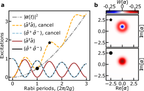
As a first example, we consider a situation where the qubit is resonant with the cavity, and model the transmon as a two-level system. In the absence of any drives, initializing the qubit in its first excited state and the cavity in the vacuum state leads to vacuum Rabi oscillations at the frequency [1], where is the Jaynes-Cummings coupling [2]. This is illustrated in Fig. 2a which shows the results (full black and red lines) of integration of the system’s master equation including cavity decay, see Supplementary Note 1 for details [17]. With the cavity drive and the cancelling tone present, the cavity population (orange dashed lines) increases following (dashed-dotted grey line) on top of which oscillations are observed. On the other hand, the qubit population (light blue dashed line) is identical to that observed in the absence of the drives. In other words, instead of collapse and revival which are expected in the presence of a coherent state in the cavity [25, 26], here the qubit undergoes oscillations at the vacuum Rabi frequency. The same conclusion holds when initializing the cavity mode in the Fock state and the qubit in the ground state (not shown). This is a clear illustration that under cloaking the qubit only couples to vacuum fluctuations of the cavity. In related work, Alsing et al. [27] have shown how a drive on the atom can suppress atomic fluorescence in the steady-state of a lossless cavity. In contrast, cloaking is an exact result which is valid at all times and in the presence of loss. Moreover, this approach can be used to prepare non-classical states of the cavity field. For example, displaced Fock states with arbitrary can be prepared by starting with the same initial state as in Fig. 2a, and waiting for half-integer Rabi periods under appropriate cavity drive amplitude and phase. The Wigner function of the displaced Fock state is plotted at 3/2 Rabi periods in Fig. 2b, and is compared to that of the coherent state at 1 Rabi period.
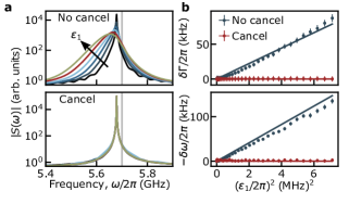
As a second example, consider the typical situation of a dispersive qubit readout where the frequency of the first drive is resonant with the cavity and the qubit-cavity detuning is large compared to such that the system is in the dispersive regime [1, 2]. In the absence of the cancellation tone, the cavity drive results in ac-Stark shift and broadening of the qubit [13, 14]. This is illustrated in the top panel of Fig. 3a which shows the numerically computed magnitude of the qubit’s absorption spectrum . For simplicity, this is obtained in the two-level approximation for the transmon where the absorption spectrum takes the form with the subscript indicating that the average is taken in steady-state. The different colored lines correspond to different cavity drive amplitudes . The vertical gray line indicates the bare qubit frequency. In contrast, the bottom panel of Fig. 3a shows the same quantity obtained with the cancellation tone present. In this case, the results for the different drive amplitudes collapse on each other. Because cloaking does not affect vacuum fluctuations, the Lamb shift (i.e. the offset from the bare qubit frequency) remains unchanged at all drive amplitudes. Moreover, the independence of the qubit linewidth on drive power indicates both the absence of measurement-induced dephasing and that Purcell decay remains at its zero-photon value [28, 29] under cloaking.
This prediction is experimentally tested on the device shown in Fig. 1c. It consists of a transmon qubit capacitively coupled to a microwave coplanar waveguide cavity which is driven through port 1 () via a Purcell filter acting as a bandpass filter at the cavity frequency. The cancellation drive () is applied to port 2, which is weakly capacitively coupled to the transmon. The readout frequency is and cavity decay rate . The transmon qubit is capacitively coupled to the cavity, with the full dispersive shift [2]. The qubit has a dressed frequency and coherence times and .
Using Ramsey interferometry, it is possible to determine the decoherence rate and the qubit frequency, and thus extract the increase in dephasing rate and the ac-Stark shift as a function of drive strength. The blue dots in Fig. 3b are obtained in the absence of cancellation drive and show the expected linear increase with drive power [13, 14]. The full lines are obtained from numerical integration of the system’s master equation including cavity loss and are used to calibrate the attenuation factor between the drive power at room temperature and for all experimental plots. The red dots correspond to the measured ac-Stark shift and increase in dephasing rate in the presence of the cancellation tone. As expected from the above discussion, with the properly tailored cancellation drive, they are both suppressed at all cavity drive powers. The cancellation drive follows the analytical expression Eq. 2 for but the attenuation and electrical delay of the line driving port 2 needs to be taken into account in order to relate the complex drive amplitude at room temperature to the driving strength . The prefactor relating the two is found experimentally by varying the phase and amplitude to minimize (see Supplementary Note 2 [17]). This technique thus provides a tool to calibrate the attenuation from room temperature to the qubit port.
The above results suggest a strategy to speed up the dispersive qubit readout. Several approaches have been explored to improve readout fidelity by speeding it up [30, 31, 32, 33, 34, 35, 36]. Here, we propose to use a two-step ‘arm and release’ approach. With the cavity in the vacuum state, the arming step consists in driving the cavity in the presence of the cancelling tone. Because the qubit is uncoupled from the cavity’s classical field, this causes a displacement of the cavity field by that is independent of the qubit-state. Thus during the pre-arming, the cavity can be stabilized in any coherent state without affecting the qubit. The release step can start at any time after the desired measurement photon population is reached: The cancellation tone is turned off, at which point the qubit couples to the cavity field resulting in a qubit-state dependent rotation of the latter in phase space under the dispersive qubit-cavity coupling. Homodyne or heterodyne detection then completes the qubit readout in the usual way [2].
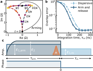
Crucially, upon release the two coherent states corresponding to the qubit ground and excited states separate as under longitudinal coupling at short times. Indeed, as illustrated in Fig. 4a, after the arming step these coherent states move away from each other in the phase space of the cavity mode (full lines), thus maximizing the qubit measurement rate [14, 36]. This is reminiscent of previous experiments [34, 33] where longitudinal-like separation is obtained with an initially empty cavity using an approach based on the dispersive approximation. In contrast, we emphasize that qubit cloaking can operate at arbitrary drive strength and qubit-cavity detuning. Figure 4a also shows the evolution in phase space of the amplitude of the readout cavity for the usual dispersive readout (dashed line), where there is initially poor separation between the qubit-state-dependent coherent states. Similarly to longitudinal readout [36], for the same steady-state photon population (see yellow dots corresponding to ), the state separation is significantly larger at short times in the arm-and-release approach than in the usual dispersive readout (see the coloured dots corresponding to times ).
The reduction in measurement time provided by the arm-and-release approach is illustrated in Fig. 4b which shows the measurement error versus integration time for the arm-and-release approach (full line) and the standard dispersive readout (dashed line) obtained using the device of Fig. 1c. In these experiments, the qubit is first prepared in the ground state using measurement-based feedback with the usual dispersive readout. As illustrated in Fig. 4c, to obtain the full line in panel b the cavity is then pre-armed with a drive of amplitude (full blue line) and a cancellation drive (dashed dark blue line) for a time . At the time labelled , the signal is then integrated for a time with a cavity drive . The arming cavity drive and the cancellation tone are omitted to obtain the dashed line in panel b. A pulse of width (orange dashed line) is applied or not at the end of the arming step to prepare the state or . Interestingly and as explained below, this can be done with high fidelity despite the cavity photon population. Finally, the measurement error is obtained by computing the overlap between the distribution of the accumulated heterodyne signal over repetitions of the experiment where the qubit is prepared either in or (see Supplementary Note 2 [17]). For a 196 ns integration time, we obtain an average fidelity where is the error probability to measure state when state was prepared, while is the error probability to measure state when state was prepared. The finite number of repetitions results in the uncertainty . The average error is mostly explained by wrong preparation of the ground state before the arming step (), imperfect pulse (), relaxation during measurement (), and finite Gaussian separation ().
In optimizing readout fidelity, it is important to account that the cavity responds at different frequencies in the absence or presence of the cancellation tone. Without cloaking, the qubit-state-dependent steady-states coherent state amplitude is , where is the dressed cavity frequency and is the dispersive qubit-cavity coupling for qubit state [2]. On the other hand, with cloaking the cavity responds as if there was no qubit with the steady-state value , where now is the bare cavity frequency. Depending on the application, such as optimizing the longitudinal-like nature of the readout, an optimal coherent state can be prepared by adequately choosing and during the arming phase, and changing these quantities as desired during the release phase; see Fig. 4c for the pulse sequence and phase used here for readout. The arming phase-space path shown in Fig. 4a is chosen to replicate our experiment, but it can be tailored. For example, a straight path is obtained by arming the cavity with a drive frequency .
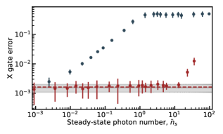
As an additional benefit, since the cloaked qubit does not undergo ac-Stark shift or measurement-induced dephasing (see Fig. 3), it is possible to apply qubit gates during the cavity arming step despite the presence of measurement photons in the cavity. As a result, the time needed to fill the cavity does not factor in the measurement time. To test this idea, we use randomized benchmarking [37, 38] on the device of Fig. 1c, and extract the gate error for a qubit -pulse (X gate) performed in the presence of a readout cavity drive, and in the absence or presence of the cancellation tone, see Fig. 5. As expected, in the absence of cancellation (blue dots) the gate error increases rapidly with the cavity drive amplitude and saturates at a gate error of 0.5, corresponding to the largest gate error which can be reported by randomized benchmarking [39]. In the presence of cancellation (red dots), the gate error remains at its coherence-limited value (full gray line) despite the presence of measurement photons in the readout cavity. The red dashed line corresponds to the result of numerical simulations accounting for the Purcell filter of the gate under cloaking, see Supplementary Note 1 [17]. Importantly, the qubit control drive is identical for all data points shown in Fig. 5. For large drive amplitudes, the X gate error under cloaking starts to increase (last three points in Fig. 5). This is explained by imperfect experimental calibration of the cancellation tone which can be affected by low-frequency drifts.
Discussion
Qubit cloaking can readily be implemented in current circuit QED experiments. This approach is valid irrespective of the driving frequency and waveshape, and applies to arbitrary qubit-cavity detuning. In the resonant regime, cloaking can be used to prepare non-classical states of the cavity [40, 41]. In the dispersive regime, cloaking can be used to speed-up qubit readout [42] something which, for example, can be used to shorten quantum error correction cycles in circuit QED-based devices [43, 44, 45]. At the heart of this acceleration is the fact that logical gates can be applied to the qubit while the cavity is armed for readout. Similar ideas can be exploited to speed up two-qubit gates that are assisted by a cavity drive, such as the resonator-induced phase gate [3] or to reduce measurement cross-talk errors in multiplexed readout [46]. Moreover, the possibility to cancel large ac-Stark shifts can be leveraged to avoid unwanted phase accumulations, such as in the preparation of bosonic codes states [12]. We expect that qubit cloaking will become a useful element in the toolbox of circuit QED, extending beyond the transmon qubit [47]. Furthermore, it is applicable to other cavity QED setups where a quantum system linearly couples to a cavity [18, 20, 21, 48, 23, 24].
Data Availability Statement
The data generated in this study have been deposited in the Figshare database [49].
References
- Haroche and Raimond [2006] S. Haroche and J.-M. Raimond, Exploring the Quantum: Atoms, Cavities, and Photons (Oxford University Press, Oxford, 2006).
- Blais et al. [2021] A. Blais, A. L. Grimsmo, S. M. Girvin, and A. Wallraff, Circuit quantum electrodynamics, Rev. Mod. Phys. 93, 025005 (2021).
- Paik et al. [2016] H. Paik, A. Mezzacapo, M. Sandberg, D. T. McClure, B. Abdo, A. D. Córcoles, O. Dial, D. F. Bogorin, B. L. T. Plourde, M. Steffen, A. W. Cross, J. M. Gambetta, and J. M. Chow, Experimental demonstration of a resonator-induced phase gate in a multiqubit circuit-QED system, Phys. Rev. Lett. 117, 250502 (2016).
- Lu et al. [2022] M. Lu, J.-L. Ville, J. Cohen, A. Petrescu, S. Schreppler, L. Chen, C. Jünger, C. Pelletti, A. Marchenkov, A. Banerjee, W. P. Livingston, J. M. Kreikebaum, D. I. Santiago, A. Blais, and I. Siddiqi, Multipartite entanglement in rabi-driven superconducting qubits, PRX Quantum 3, 040322 (2022).
- Leghtas et al. [2015] Z. Leghtas, S. Touzard, I. M. Pop, A. Kou, B. Vlastakis, A. Petrenko, K. M. Sliwa, A. Narla, S. Shankar, M. J. Hatridge, M. Reagor, L. Frunzio, R. J. Schoelkopf, M. Mirrahimi, and M. H. Devoret, Confining the state of light to a quantum manifold by engineered two-photon loss, Science 347, 853 (2015).
- Gao et al. [2018] Y. Y. Gao, B. J. Lester, Y. Zhang, C. Wang, S. Rosenblum, L. Frunzio, L. Jiang, S. M. Girvin, and R. J. Schoelkopf, Programmable interference between two microwave quantum memories, Phys. Rev. X 8, 021073 (2018).
- Grimm et al. [2020] A. Grimm, N. E. Frattini, S. Puri, S. O. Mundhada, S. Touzard, M. Mirrahimi, S. M. Girvin, S. Shankar, and M. H. Devoret, Stabilization and operation of a Kerr-cat qubit, Nature 584, 205 (2020).
- Berdou et al. [2023] C. Berdou, A. Murani, U. Réglade, W. Smith, M. Villiers, J. Palomo, M. Rosticher, A. Denis, P. Morfin, M. Delbecq, T. Kontos, N. Pankratova, F. Rautschke, T. Peronnin, L.-A. Sellem, P. Rouchon, A. Sarlette, M. Mirrahimi, P. Campagne-Ibarcq, S. Jezouin, R. Lescanne, and Z. Leghtas, One hundred second bit-flip time in a two-photon dissipative oscillator, PRX Quantum 4, 020350 (2023).
- Blais et al. [2004] A. Blais, R.-S. Huang, A. Wallraff, S. M. Girvin, and R. J. Schoelkopf, Cavity quantum electrodynamics for superconducting electrical circuits: An architecture for quantum computation, Phys. Rev. A 69, 062320 (2004).
- Minev et al. [2019] Z. K. Minev, S. O. Mundhada, S. Shankar, P. Reinhold, R. Gutiérrez-Jáuregui, R. J. Schoelkopf, M. Mirrahimi, H. J. Carmichael, and M. H. Devoret, To catch and reverse a quantum jump mid-flight, Nature 570, 200 (2019).
- Walter et al. [2017] T. Walter, P. Kurpiers, S. Gasparinetti, P. Magnard, A. Potočnik, Y. Salathé, M. Pechal, M. Mondal, M. Oppliger, C. Eichler, and A. Wallraff, Rapid high-fidelity single-shot dispersive readout of superconducting qubits, Phys. Rev. Applied 7, 054020 (2017).
- Eickbusch et al. [2022] A. Eickbusch, V. Sivak, A. Z. Ding, S. S. Elder, S. R. Jha, J. Venkatraman, B. Royer, S. Girvin, R. J. Schoelkopf, and M. H. Devoret, Fast universal control of an oscillator with weak dispersive coupling to a qubit, Nature Physics 18, 1464 (2022).
- Schuster et al. [2005] D. I. Schuster, A. Wallraff, A. Blais, L. Frunzio, R.-S. Huang, J. Majer, S. M. Girvin, and R. J. Schoelkopf, ac Stark shift and dephasing of a superconducting qubit strongly coupled to a cavity field, Phys. Rev. Lett. 94, 123602 (2005).
- Gambetta et al. [2006] J. Gambetta, A. Blais, D. I. Schuster, A. Wallraff, L. Frunzio, J. Majer, M. H. Devoret, S. M. Girvin, and R. J. Schoelkopf, Qubit-photon interactions in a cavity: Measurement-induced dephasing and number splitting, Phys. Rev. A 74, 042318 (2006).
- Kirchmair et al. [2013] G. Kirchmair, B. Vlastakis, Z. Leghtas, S. E. Nigg, H. Paik, E. Ginossar, M. Mirrahimi, L. Frunzio, S. M. Girvin, and R. J. Schoelkopf, Observation of quantum state collapse and revival due to the single-photon Kerr effect, Nature 495, 205 (2013).
- Koch et al. [2007] J. Koch, T. M. Yu, J. Gambetta, A. A. Houck, D. I. Schuster, J. Majer, A. Blais, M. H. Devoret, S. M. Girvin, and R. J. Schoelkopf, Charge-insensitive qubit design derived from the Cooper pair box, Phys. Rev. A 76, 042319 (2007).
- [17] See Supplementary Information.
- Mi et al. [2017] X. Mi, J. V. Cady, D. M. Zajac, P. W. Deelman, and J. R. Petta, Strong coupling of a single electron in silicon to a microwave photon, Science 355, 156 (2017), https://www.science.org/doi/pdf/10.1126/science.aal2469 .
- Landig et al. [2018] A. J. Landig, J. V. Koski, P. Scarlino, U. C. Mendes, A. Blais, C. Reichl, W. Wegscheider, A. Wallraff, K. Ensslin, and T. Ihn, Coherent spin–photon coupling using a resonant exchange qubit, Nature 560, 179 (2018).
- Stockklauser et al. [2017] A. Stockklauser, P. Scarlino, J. V. Koski, S. Gasparinetti, C. K. Andersen, C. Reichl, W. Wegscheider, T. Ihn, K. Ensslin, and A. Wallraff, Strong coupling cavity QED with gate-defined double quantum dots enabled by a high impedance resonator, Phys. Rev. X 7, 011030 (2017).
- Samkharadze et al. [2018] N. Samkharadze, G. Zheng, N. Kalhor, D. Brousse, A. Sammak, U. C. Mendes, A. Blais, G. Scappucci, and L. M. K. Vandersypen, Strong spin-photon coupling in silicon, Science 359, 1123 (2018).
- Zhou et al. [2022] X. Zhou, G. Koolstra, X. Zhang, G. Yang, X. Han, B. Dizdar, X. Li, R. Divan, W. Guo, K. W. Murch, D. I. Schuster, and D. Jin, Single electrons on solid neon as a solid-state qubit platform, Nature 605, 46 (2022).
- Manenti et al. [2017] R. Manenti, A. F. Kockum, A. Patterson, T. Behrle, J. Rahamim, G. Tancredi, F. Nori, and P. J. Leek, Circuit quantum acoustodynamics with surface acoustic waves, Nat. Comm. 8, 975 (2017).
- Ye et al. [1999] J. Ye, D. W. Vernooy, and H. J. Kimble, Trapping of single atoms in cavity QED, Phys. Rev. Lett. 83, 4987 (1999).
- Brune et al. [1996] M. Brune, F. Schmidt-Kaler, A. Maali, J. Dreyer, E. Hagley, J. M. Raimond, and S. Haroche, Quantum Rabi oscillation: A direct test of field quantization in a cavity, Phys. Rev. Lett. 76, 1800 (1996).
- Eberly et al. [1980] J. H. Eberly, N. B. Narozhny, and J. J. Sanchez-Mondragon, Periodic spontaneous collapse and revival in a simple quantum model, Phys. Rev. Lett. 44, 1323 (1980).
- Alsing et al. [1992] P. M. Alsing, D. A. Cardimona, and H. J. Carmichael, Suppression of fluorescence in a lossless cavity, Phys. Rev. A 45, 1793 (1992).
- Boissonneault et al. [2010] M. Boissonneault, J. M. Gambetta, and A. Blais, Improved superconducting qubit readout by qubit-induced nonlinearities, Phys. Rev. Lett. 105, 100504 (2010).
- Sete et al. [2014] E. A. Sete, J. M. Gambetta, and A. N. Korotkov, Purcell effect with microwave drive: Suppression of qubit relaxation rate, Phys. Rev. B 89, 104516 (2014).
- Jeffrey et al. [2014] E. Jeffrey, D. Sank, J. Y. Mutus, T. C. White, J. Kelly, R. Barends, Y. Chen, Z. Chen, B. Chiaro, A. Dunsworth, A. Megrant, P. J. J. O’Malley, C. Neill, P. Roushan, A. Vainsencher, J. Wenner, A. N. Cleland, and J. M. Martinis, Fast accurate state measurement with superconducting qubits, Phys. Rev. Lett. 112, 190504 (2014).
- McClure et al. [2016] D. T. McClure, H. Paik, L. S. Bishop, M. Steffen, J. M. Chow, and J. M. Gambetta, Rapid driven reset of a qubit readout resonator, Phys. Rev. Applied 5, 011001 (2016).
- Bultink et al. [2016] C. C. Bultink, M. A. Rol, T. E. O’Brien, X. Fu, B. C. S. Dikken, C. Dickel, R. F. L. Vermeulen, J. C. de Sterke, A. Bruno, R. N. Schouten, and L. DiCarlo, Active resonator reset in the nonlinear dispersive regime of circuit QED, Phys. Rev. Applied 6, 034008 (2016).
- Touzard et al. [2019] S. Touzard, A. Kou, N. E. Frattini, V. V. Sivak, S. Puri, A. Grimm, L. Frunzio, S. Shankar, and M. H. Devoret, Gated conditional displacement readout of superconducting qubits, Phys. Rev. Lett. 122, 080502 (2019).
- Ikonen et al. [2019] J. Ikonen, J. Goetz, J. Ilves, A. Keränen, A. M. Gunyho, M. Partanen, K. Y. Tan, D. Hazra, L. Grönberg, V. Vesterinen, S. Simbierowicz, J. Hassel, and M. Möttönen, Qubit measurement by multichannel driving, Phys. Rev. Lett. 122, 080503 (2019).
- Peronnin et al. [2020] T. Peronnin, D. Marković, Q. Ficheux, and B. Huard, Sequential dispersive measurement of a superconducting qubit, Phys. Rev. Lett. 124, 180502 (2020).
- Didier et al. [2015] N. Didier, J. Bourassa, and A. Blais, Fast quantum nondemolition readout by parametric modulation of longitudinal qubit-oscillator interaction, Phys. Rev. Lett. 115, 203601 (2015).
- Dankert et al. [2009] C. Dankert, R. Cleve, J. Emerson, and E. Livine, Exact and approximate unitary 2-designs and their application to fidelity estimation, Phys. Rev. A 80, 012304 (2009).
- Magesan et al. [2011] E. Magesan, J. M. Gambetta, and J. Emerson, Scalable and robust randomized benchmarking of quantum processes, Phys. Rev. Lett. 106, 180504 (2011).
- Knill et al. [2008] E. Knill, D. Leibfried, R. Reichle, J. Britton, R. B. Blakestad, J. D. Jost, C. Langer, R. Ozeri, S. Seidelin, and D. J. Wineland, Randomized benchmarking of quantum gates, Phys. Rev. A 77, 012307 (2008).
- Uria et al. [2020] M. Uria, P. Solano, and C. Hermann-Avigliano, Deterministic generation of large Fock states, Phys. Rev. Lett. 125, 093603 (2020).
- Long et al. [2022] D. M. Long, P. J. D. Crowley, A. J. Kollár, and A. Chandran, Boosting the quantum state of a cavity with Floquet driving, Phys. Rev. Lett. 128, 183602 (2022).
- Muñoz-Arias et al. [2023] M. H. Muñoz-Arias, C. Lledó, and A. Blais, Qubit readouts enabled by qubit cloaking, arXiv preprint arXiv:2305.00895 (2023).
- AI [2021] G. Q. AI, Exponential suppression of bit or phase errors with cyclic error correction, Nature 595, 383 (2021).
- Krinner et al. [2022] S. Krinner, N. Lacroix, A. Remm, A. Di Paolo, E. Genois, C. Leroux, C. Hellings, S. Lazar, F. Swiadek, J. Herrmann, et al., Realizing repeated quantum error correction in a distance-three surface code, Nature 605, 669 (2022).
- Zhao et al. [2022] Y. Zhao, Y. Ye, H.-L. Huang, Y. Zhang, D. Wu, H. Guan, Q. Zhu, Z. Wei, T. He, S. Cao, F. Chen, T.-H. Chung, H. Deng, D. Fan, M. Gong, C. Guo, S. Guo, L. Han, N. Li, S. Li, Y. Li, F. Liang, J. Lin, H. Qian, H. Rong, H. Su, L. Sun, S. Wang, Y. Wu, Y. Xu, C. Ying, J. Yu, C. Zha, K. Zhang, Y.-H. Huo, C.-Y. Lu, C.-Z. Peng, X. Zhu, and J.-W. Pan, Realization of an error-correcting surface code with superconducting qubits, Phys. Rev. Lett. 129, 030501 (2022).
- Heinsoo et al. [2018] J. Heinsoo, C. K. Andersen, A. Remm, S. Krinner, T. Walter, Y. Salathé, S. Gasparinetti, J.-C. Besse, A. Potočnik, A. Wallraff, and C. Eichler, Rapid high-fidelity multiplexed readout of superconducting qubits, Phys. Rev. Appl. 10, 034040 (2018).
- Gyenis et al. [2021] A. Gyenis, A. Di Paolo, J. Koch, A. Blais, A. A. Houck, and D. I. Schuster, Moving beyond the transmon: Noise-protected superconducting quantum circuits, PRX Quantum 2, 030101 (2021).
- Keyser et al. [2020] A. K. Keyser, J. J. Burnett, S. E. Kubatkin, A. V. Danilov, M. Oxborrow, S. E. de Graaf, and T. Lindström, Pulsed electron spin resonance of an organic microcrystal by dispersive readout, J. Magn. Reson. 321, 106853 (2020).
- Lledó et al. [2023] C. Lledó, R. Dassonneville, A. Moulinas, J. Cohen, R. Shillito, A. Bienfait, B. Huard, and A. Blais, Data for Cloaking a qubit in a cavity, figshare http://dx.doi.org/10.6084/m9.figshare.24147135.v2 (2023).
Acknowledgements
The authors are grateful to Élie Genois for helpful discussions and to Lincoln Labs and IARPA from providing the TWPA.
-
•
NSERC – A. Moulinas and A. Blais
-
•
Canada First Research Excellence Fund – C. Lledó, A. Moulinas, J. Cohen, R. Shillito, and A. Blais
-
•
U.S. Army Research Office Grant No. W911NF-18-1-0411 – J. Cohen, R. Shillito, and A. Blais
-
•
Ministère de l’Économie et de l’Innovation du Québec – C. Lledó and A. Blais
-
•
France 2030 grant ANR-22-PETQ-0006 R. Dassonneville, A. Bienfait, and B. Huard
-
•
ANR grant ANR-21-CE47-0007 – R. Dassonneville, A. Bienfait, and B. Huard
Author Contributions Statement
C. Lledó and R. Dassonneville contributed equally.
C. Lledó and A. Moulinas performed the calculations.
R. Dassonneville performed the measurements.
R. Shillito provided codes.
C. Lledó, R. Dassonneville, A. Moulinas, J. Cohen, A. Bienfait, B. Huard, and A. Blais analyzed and discussed the results.
C. Lledó, R. Dassonneville, and A. Blais wrote the manuscript with comments from all the authors.
A. Bienfait, B. Huard, and A. Blais supervised the work.
Competing interests
B. H. is an equity shareholder of the Alice&Bob company. The remaining authors declare no competing interests.