Effect of Decoherence for Gate Operations on a Superconducting Bosonic Qubit
Abstract
High-quality-factor 3D cavities in superconducting circuits are ideal candidates for bosonic logical qubits as their fidelity is limited only by the low photon loss rate. However, the transmon qubits that are used to manipulate bosonic qubits result in the emergence of additional relaxation and dephasing channels. In this work, a numerical study is performed to elucidate the effect of the various loss channels on the performance of logical gates on a bosonic qubit. A gate error model is developed that encapsulates the loss mechanisms for arbitrary gate operations and predicts experimentally achievable gate errors for bosonic qubits. The insights gleaned from this study into loss mechanisms suggest more efficient optimization algorithms that could reduce gate errors on bosonic qubits.
Keywords: superconducting bosonic qubit, decoherence, gate error
1 Introduction
Encoding quantum information into a harmonic oscillator mode of a superconducting cavity offers a hardware-efficient approach to quantum computing through the large Hilbert space available to this architecture [1]. The resultant superconducting bosonic qubits have so far yielded unprecedented lifetimes as they are prone to only photon loss [2, 3, 4]. More impressively, the photon-loss error can be mitigated via error correcting codes [5], thus offering the possibility of bosonic logical qubits with unprecedented performance. However, a nonlinear element is required to manipulate these near harmonic qubits and implement various quantum operations with high fidelity [6] (for instance, state preparation [7], logical gate operations [8, 9, 10], quantum non-demolition (QND) measurements [11, 12], error correcting gates [13, 14], and multi-cavity operations [15, 16, 17]). In superconducting circuits, this requirement can be satisfied by introducing an ancilla transmon qubit that provides a nonlinearity [18] with which to manipulate the bosonic qubit by using numerically optimized protocols [19, 8, 13].
Numerical optimization can be used to generate intricate waveforms with which high-fidelity operations can be realized. However, the transmon introduces not only a nonlinearity but also additional decoherence channels, namely relaxation and dephasing, whose rates are generally higher than the photon loss rate of the cavity. Although numerical gate implementations on bosonic qubits have been studied, the effects of the underlying decoherence channels on gate errors are challenging to decipher because of the intricate transmon-cavity entangled states that briefly emerge during the optimally controlled gate evolution. In previous studies, Heeres et al. [8] reported that the dominant source of gate errors was transmon dephasing, whereas Hu et al. [13] reported that it was transmon relaxation. Even though these studies employed similar device architectures, their gate errors were limited by different mechanisms. Therefore, a fundamental question emerges: how do the various decoherence channels affect gate errors on a bosonic qubit?
This work investigates the effect of decoherence, namely transmon relaxation, transmon dephasing, and cavity photon loss, on the errors of numerically optimized gates on bosonic qubits in superconducting circuits. First, logical gate operations on a bosonic qubit, encoded with the lowest order binomial code [5], were generated by numerical optimization under the assumption of no decoherence. Then, the gate errors of these operations in the presence of realistic decoherence were evaluated by solving the Lindblad equation. Next, we developed a gate error model to encapsulate the various decoherence effects on any unitary gate operation. This model quantitatively describes the contribution of each decoherence channel for the optimized gates. It yields an approximate lower bound for the achievable gate error on a bosonic qubit. Specifically, for the Hadamard gate, a gate error can be achieved when a transmon with a relaxation time of and a pure dephasing time of is coupled to a cavity with a lifetime of .
Furthermore, the numerical and statistical analyses reveal a qualitative difference between gate errors stemming from transmon relaxation and cavity photon loss. By comparing errors in repeatedly optimized Hadamard gates, it is found that the contribution from transmon relaxation varies significantly across the gates, whereas the contribution from cavity photon loss exhibits a smaller variance. Even though the gates each have wholly different waveforms that lead to unique transmon-cavity entangled states as the bosonic qubit evolves, the contribution of the cavity photon loss to the gate error remains insensitive to the underlying gate operation. The gate error model not only describes the physical mechanism of this insensitivity, but also indicates that it is a feature of cavity modes driven by displacement. These insights further suggest optimization algorithms that can handle decoherence effects with only modest numerical costs, which could lead to reduced gate errors.
The rest of the paper is organized as follows. Section 2 describes superconducting bosonic qubits and quantum optimal control. Section 3 shows errors of numerically optimized gates and the contributions to the error from the cavity photon loss and transmon relaxation. Section 4 introduces our gate error model, and Section 5 describes the properties of the decoherence channels that are revealed with it. In Section 6.1, the minimum gate error on a binomial bosconic qubit is estimated. Section 6.2 discusses optimization algorithms that include decoherence effects with mitigated computational complexity.
2 Bosonic Qubits and Quantum Optimal Control
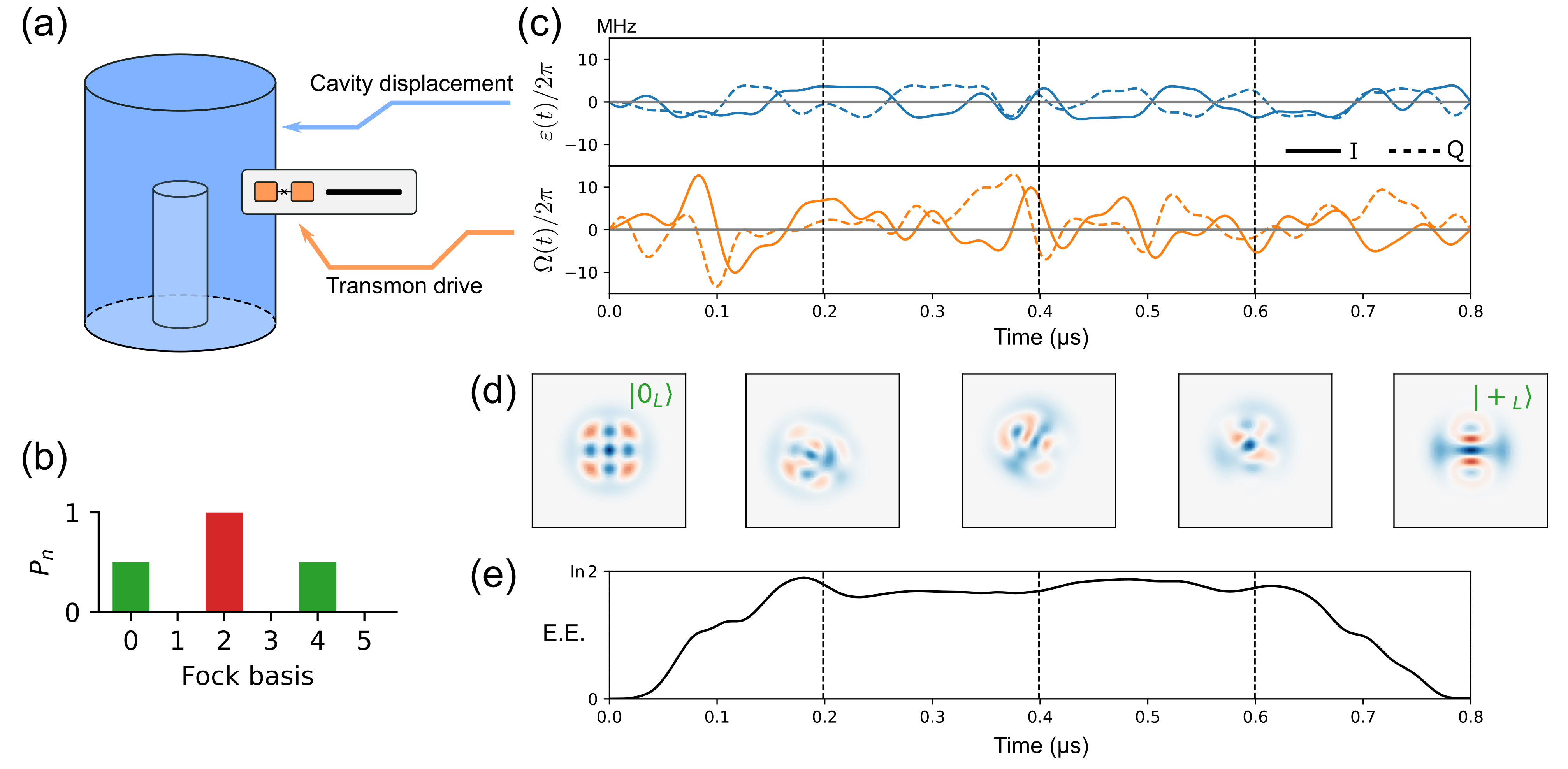
In a bosonic qubit, quantum information is encoded as a superposition of the Fock states in an oscillator mode in a coaxial cavity (Fig. 1(a), blue) [4]. Although several bosonic codes [20, 21, 22, 23, 24] have been proposed to protect quantum information from photon loss, binomial codes [5] have emerged as an important class due to their compact photon distributions that lead to high-fidelity gate operations. Here, the lowest order binomial (Bin(1,1)) code is employed, and the logical codewords are defined as
| (1) |
The quantum information is protected when an error due to cavity photon loss occurs, as this error can be detected and corrected. This protection stems from the photon distributions of the codewords having a distinct separation in the Fock basis (Fig. 1(b)), thus enabling the quantum state to be readily identified in the error space, but with the penalty of requiring non-trivial protocols to execute logical gate operations. Such operations can be implemented by coupling the cavity to an ancilla transmon qubit [25](Fig. 1(a), orange) with a combined system Hamiltonian in a rotating frame given by:
| (2) | |||
| (3) | |||
| (4) |
where , , and correspond to the annihilation operator of the cavity, the Pauli operators of the transmon, and the dispersive coupling strength, respectively [1]. Eq.(4) describes the control Hamiltonian for a bosonic qubit, where and correspond to the in- and quadrature-phase amplitudes of the transmon drive (microwave pulses at the transition frequency between and states of the transmon) and the cavity displacement (microwave pulses at the cavity frequency). These controls constitute a necessary prerequisite to implementing arbitrary gate operations for a bosonic qubit [26, 27].
Non-trivial operations on bosonic qubits are realized by a quantum optimal control based on a numerical optimization with the gradient ascent pulse engineering (GRAPE) algorithm [28]. The concept of this algorithm is first described for a simple system with a time-dependent Hamiltonian , where is the amplitude and is the Hamiltonian corresponding to the control. The aim of this optimization is to obtain a waveform that yields the target unitary operator . The waveform is parameterized, for example, like a Fourier series , where is the frequency of the -th element. By dividing the gate time into time steps, the amplitudes are discretized as for . From the Schrödinger equation in natural units of , the propagator in the -th time step is calculated as . Thus, the total unitary operator of this control is , and the cost function corresponding to the gate error is given by , where is the dimension of the codespace. The GRAPE algorithm enables an efficient gradient calculation of the cost function with respect to the control amplitudes as well as the gradients with respect to the parameter via the chain rule, namely . A gradient-based optimizer minimizes the cost function and yields a parameter set whose total unitary operator emulates the target operator [29]. This method can easily be extended to a system with multiple controls; the optimization for a bosonic qubit is detailed in B.1. Note that the cost function includes penalties limiting the waveform amplitude and bandwidth to generate realistic waveforms [8].
The waveforms and resultant errors of an optimized gate critically depend on its initial parameters, which indicates the existence of many local minima that make it challenging to find a globally optimal solution (see B.3). This problem can be indirectly addressed by repeating the gate optimizations with multiple random initial parameters. The gate fidelity from multiple optimizations can then be evaluated by performing simulations with the Schrödinger or Lindblad equations, from which the gate error can be calculated (see A.1 and B.2). Four decoherence channels are considered in the simulations reported here: cavity photon loss (with loss rate and jump operator ), transmon relaxation , pure dephasing of the transmon , and thermal excitation of the transmon . The Lindblad equation with the aforementioned decoherences can faithfully simulate the system dynamics [8].
We should emphasize that the numerical experiments in this study are composed of two steps. First, gate optimizations in a closed space are executed with random initial parameters; thus, decoherence is not considered in this step. Then, the errors of the numerically optimized gates are evaluated by solving the Schrödinger and Lindblad equations.
Figure 1(c) shows the waveforms for the Hadamard gate for the Bin(1,1) code, and Fig. 1(d) shows the Wigner functions of the cavity under the gate operation. The initial state is converted into the final state . Although the cavity and transmon are not entangled before and after the gate, the intermediate states are almost maximally entangled (Fig. 1(e)). This makes it challenging to use numerical optimization to interpret the effect of decoherence during the gate evolution. Note that gate operations on bosonic qubits are classified into phase gates and non-phase gates (see D). Phase gates (e.g., gate and parity mapping operations) generally exhibit high fidelity because they preserve the photon distribution of the cavity states. On the other hand, non-phase gates (e.g., the gate, Hadamard gate, error correction gates, and displacement operations) tend to show low fidelity because they change the photon distribution [8]. Most non-phase gates exhibit similar average fidelities; the Hadamard gate investigated in this study is a representative of this gate class.
3 Gate Errors of Numerically Optimized Gates
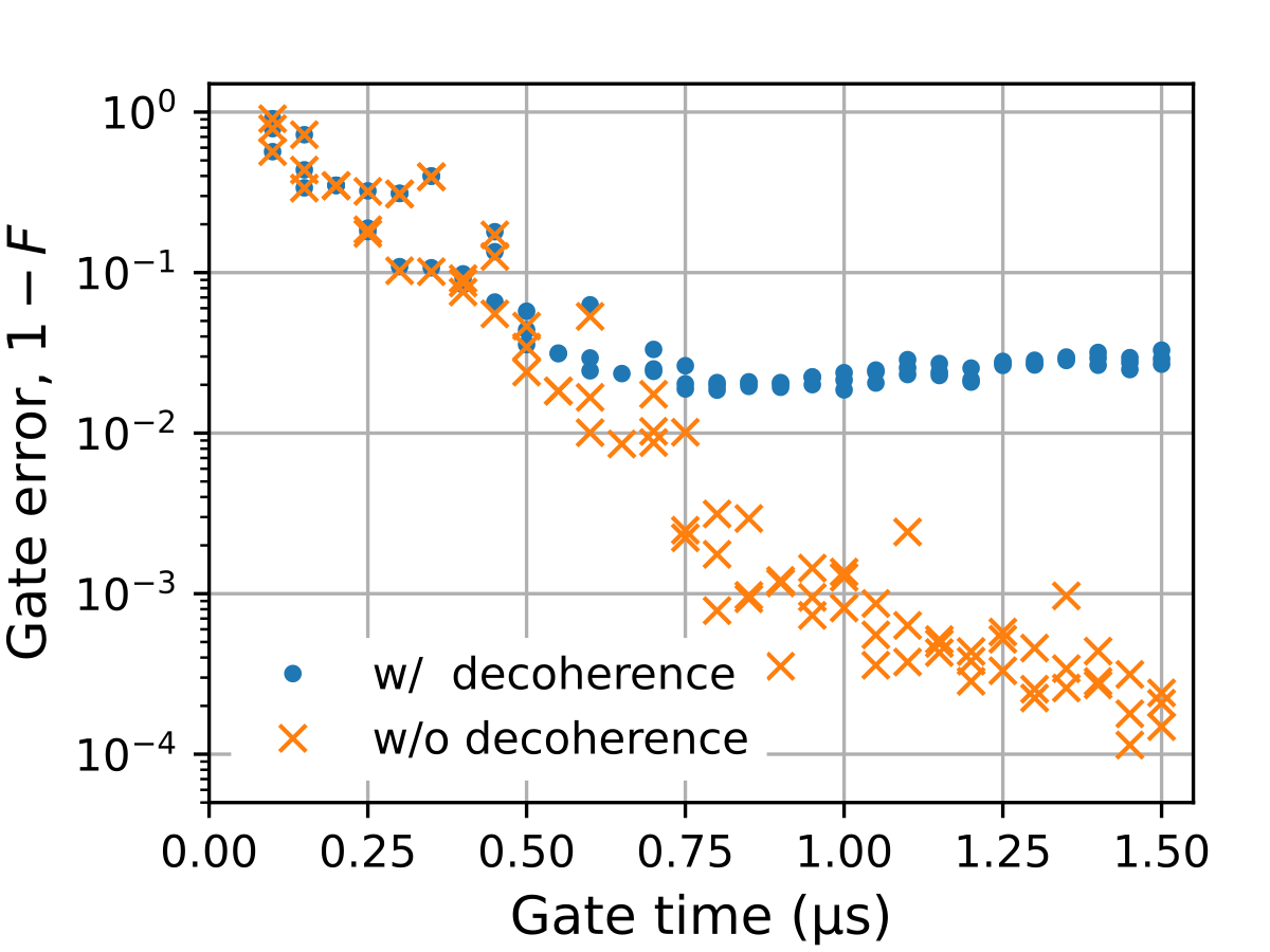
Figure 2 shows the errors of the optimized Hadamard gates as a function of gate time. The plots reveal that, although longer gates yield less errors in the absence of decoherence, the error saturates at longer gate times in a more realistic device with finite decoherence rates. The minimal gate error is around with , , , and where the dispersive coupling strength is fixed to (and is used throughout this study). Note that state-of-the-art bosonic qubits have superior coherence properties to the above quoted values [9].
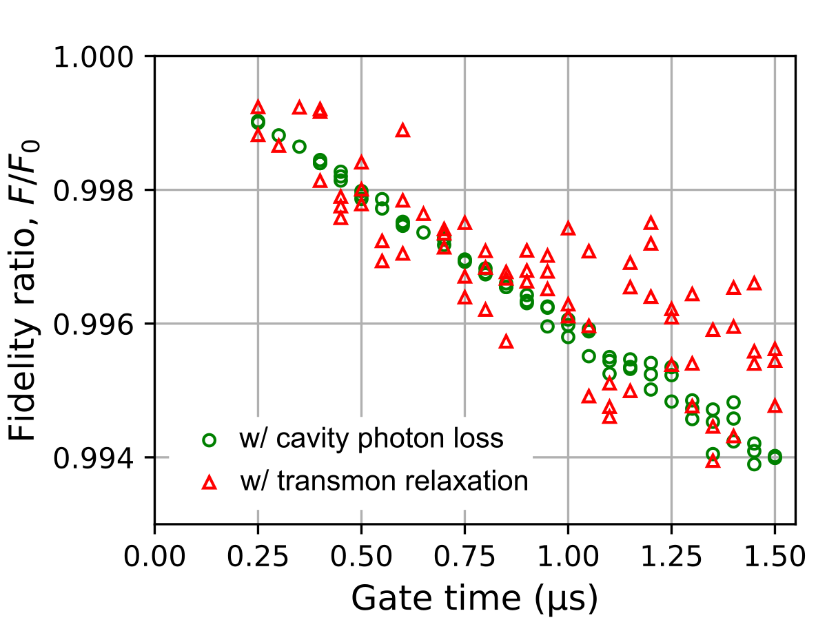
The contribution of each decoherence channel to the overall gate error can be revealed by calculating the ratio where is the gate fidelity in the case of a single decoherence channel and is the intrinsic gate fidelity without decoherence. The red triangles in Fig. 3 correspond to the fidelity ratio in the case of transmon relaxation (). These plots exhibit variations stemming from the fact that the cost function for gate optimization has multiple local minima. For a given gate time, each optimization results in a different waveform that depends on the initial parameter set (see B.3), which leads to radically different intermediate transmon-cavity entangled states during the gate evolution. The resultant decoherence is strongly dependent on the details of the intermediate states, which causes a large variation in gate fidelity when the decoherence source is transmon relaxation. This behavior is consistent with the findings of a previous study on a spin-chain system [30].
The fidelity ratio in the case of cavity photon loss (green circles in Fig. 3) is markedly different from the case of transmon relaxation. Although a loss rate causes a similar magnitude of gate errors as transmon relaxation when averaged at each gate time, the fidelity ratio exhibits a much smaller variation. It should be emphasized that the variations of the ratios for the cavity photon loss and transmon relaxation are radically different for the same optimized gates. In particular, the effect of the photon loss channel is almost independent of the different intermediate states that emerge during each gate evolution. In the following section, a gate error model is developed that can describe the features of this contrasting behavior.
4 Gate Error Model for Arbitrary Gate Operations
An error budget analysis that is used in simple protocols like QND measurements based on Ramsey interferometry [11, 12] can evaluate errors in terms of the product of the gate time, decoherence rate, and impact of a given decoherence. Although the effect of decoherence is constant in a Ramsey measurement, this is not the case for numerically optimized gate operations. In what follows, we extend the error budget analysis to handle arbitrary unitary operations. Our gate error model represents the decoherence-induced gate error as a weighted sum of the decoherence rates of the system, , where denotes a decoherence channel, the decoherence rate, and the error susceptibility (described later).
First, this model is considered in the case of a single decoherence channel with an initial state and an intermediate state at time given by . The probability of an error in unit time is given by , where corresponds to the jump operator of the decoherence channel , and henceforth we coin as the error probability at . If an error on the state occurs at time , the system falls into [31]. The impact of the error can be quantified by the fidelity between the states just before and after, as . Hence, the contribution of decoherence on the gate error in a short time is given by the product of the probability and fidelity deterioration:
| (5) | |||
| (6) |
where corresponds to the error susceptibility at . By integrating with respect to time, the gate error induced by decoherence can be determined. Moreover, the initial state can be any superposition of the logical codewords, so we average it on the logical Bloch sphere (), yielding:
| (7) | |||
| (8) |
where denotes the error susceptibility of the gate operation. Next, we generalize the above argument to a case with multiple decoherence channels by expressing the decoherence-induced gate error as a weighted sum of the decoherence rates:
| (9) |
It should be noted that this approach is premised on (1) a Markovian assumption in which the Lindblad equation describes the system dynamics and (2) weak decoherence, namely . A detailed derivation is given in C.1. By comparing the gate errors estimated by Eq.(9) and the Lindblad equation, it can be seen that our analysis quantitatively captures the effects of decoherence on gate errors (see C.2).
For later convenience, we will introduce unnormalized fidelity at as , which satisfies
| (10) |
Explicitly, and denote the contribution of decoherence to the gate error and the probability of decoherence, respectively. Thus, indicates how tolerant the state is to decoherence. Moreover, and denote the average values of and in analogy to Eq.(8); they satisfy .
5 Decoherence in Bosonic Qubits during Gate Operations
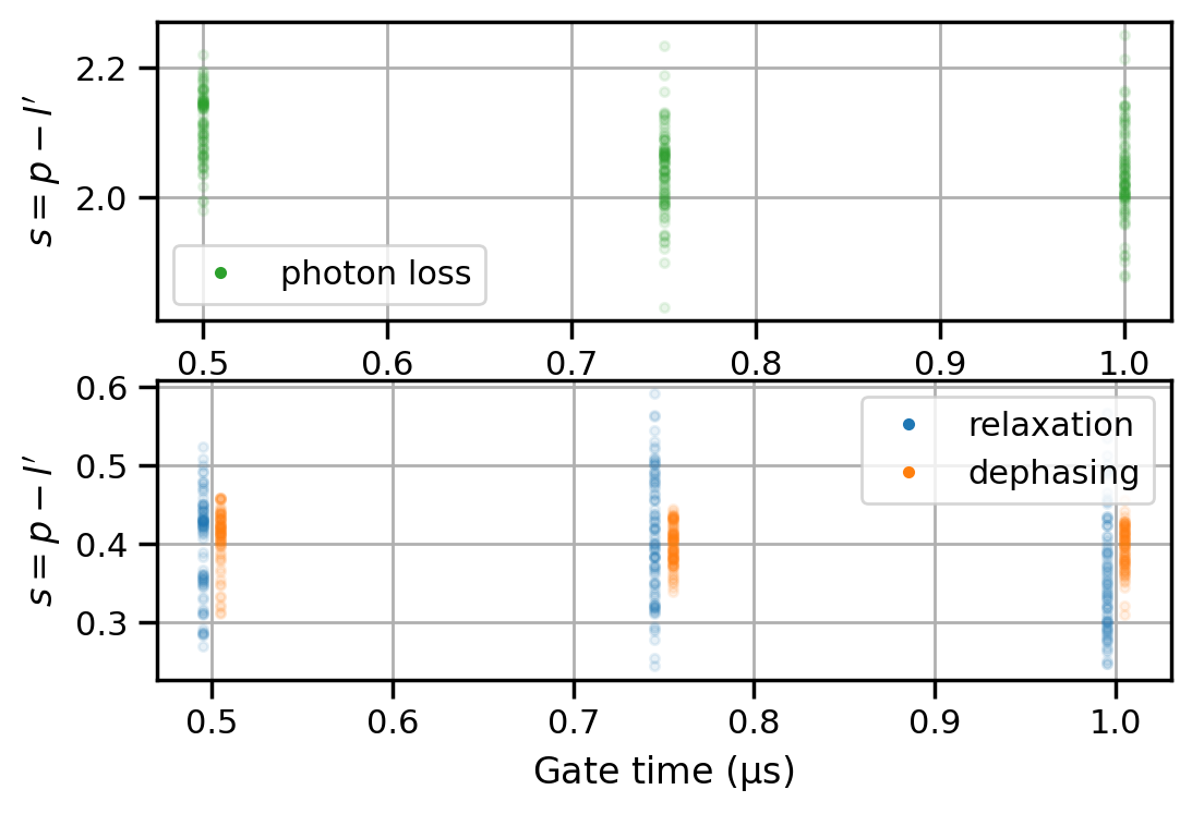
To evaluate the effect of decoherence on a bosonic qubit, the error susceptibilities were calculated for the cavity photon loss, transmon relaxation, and pure dephasing of transmon for 100 optimized gates with . Thermal excitation of the transmon was ignored since it contributes approximately to the transmon relaxation. Figure 4(a) shows histograms of the error susceptibility . The relative standard deviation (RSD), defined as the ratio of the standard deviation to the average , is 0.033 for the cavity photon loss, 0.068 for transmon dephasing, and 0.208 for transmon relaxation (Table 1 and Fig. 4(a, inset)). The average error susceptibilities for transmon relaxation and dephasing are close to , which is reminiscent of the average idle gate error in a two-level system (Ref. [32], see also C.4). However, their standard deviations are different (), and the RSD for transmon dephasing is small. On the other hand, the average error susceptibility for the cavity photon loss is larger than the average for the transmon relaxation (), while their standard deviations are similar (). The corresponding RSD for the cavity photon loss is much smaller than the RSD for transmon relaxation, thus confirming the observations in Fig. 3. Although the contrasting behaviors of the transmon relaxation and cavity photon loss can be described in terms of the RSD of their error susceptibilities, two questions arise: (1) why is larger than the average of the transmon relaxation despite their standard deviations being similar? (2) Why is smaller than the standard deviation of the transmon relaxation despite their averages being similar?

| Decoherence channel | Average | Standard deviation | RSD |
|---|---|---|---|
| Transmon relaxation | 0.363 | 0.075 | 0.208 |
| Transmon dephasing | 0.396 | 0.027 | 0.068 |
| Cavity photon loss | 2.038 | 0.069 | 0.033 |
Interestingly, the average error susceptibility of cavity photon loss of 2.038 is close to the mean photon number of the underlying codewords . To confirm this observation, error susceptibilities were calculated for other bosonic codes with higher mean photon numbers (4-leg cat code with and the Bin(2,2) code with , see A.2). In these encodings, the error susceptibilities for photon loss are also distributed around their mean photon numbers (see E). To account for this similarity, we consider the cavity mode undergoes a displacement, namely and in Eq.(4) during the gate operation. This displacement increases the mean photon number, which intuitively suggests a larger gate error induced by photon loss. However, the displacement concurrently broadens the photon distribution, making it less sensitive to photon loss. For example, the first Fock state is completely destroyed by photon loss: , but the coherent state is not affected: . To verify this explanation, Fig. 4(b) shows an example of , , and during an optimized Hadamard gate operation on the Bin(1,1) code with . Note that corresponds to the instantaneous mean photon number at , and corresponds to how tolerant the intermediate state is to photon loss. The gate operation causes to increase from its initial value of because the cavity undergoes displacement. Interestingly, the temporal dynamics of are similar to thus canceling each other, and consequently, remains close to . For a simple system, a cavity without an ancilla, the dynamics of and exactly coincide. Due to the fact that and , the relationship is thus satisfied, making this a key feature of cavity modes encoded with bosonic codes (see C.3).
As an illustration of relationship between error probability and unnormalized fidelity, Fig. 4(c) shows and for the optimized gates used in Fig. 4(a). Note that and were averaged over time and initial states for each gate. It shows that the cavity photon loss exhibits a clear correlation with and in line with the explanation above. Note that the green dots in the figure are scattered around the dashed line indicating . This distribution emerges from the dispersive interaction and the resultant entanglement between the cavity and the transmon. These observations were further verified in two additional cases: Hadamard gates with stronger displacement and error correction gates (see G and F).
The above findings indicate that even large displacements do not increase the gate error due to photon loss during gate operations. This insight is important because a larger displacement allows for a shorter gate, leading to smaller errors [33]. Indeed, it explains the observations in Ref. [33], in which faster operations were demonstrated by utilizing large displacements that resulted in mean photon numbers up to 2500. In spite of this, the cavity photon loss still inflicts smaller errors on the gate operations compared with the transmon decoherence channels.
In contrast to the case of the cavity photon loss, the error susceptibility for transmon dephasing is determined only by the unnormalized fidelity: . Note that . Moreover, the error susceptibility for transmon relaxation is approximately determined by the error probability: . From and , the standard deviation of the error susceptibility for transmon dephasing is roughly of the order , whereas for relaxation it is . Since the expectation value of spans , the error susceptibility for dephasing has a smaller variance than that for relaxation, as shown in Fig. 4(a) (see also C.5).
6 Discussion
6.1 Bounding of Gate Errors for Bin(1,1) Bosonic Qubits
In this section, we will discuss the experimentally achievable gate errors. Gate errors can be decomposed into intrinsic and decoherence contributions: . Even without decoherence, an optimized gate has a non-zero error, which we term intrinsic error that can be evaluated by solving the Schrödinger equation.
First, the results of Secion 5 allows us to estimate the lower bound on decoherence-induced gate errors . It can be approximated with Eq.(9):
| (11) |
where the minimum error susceptibility for each channel has been utilized for the prefactors. The prefactor for the photon loss term is divided by the mean photon number. Substituting , , , , and into Eq.(11) yields a gate error of . The minimum gate error of the optimized gates used in Fig. 4 was , and thus we can approximate the lower bound by Eq.(11). Note that the error susceptibility exhibits only a weak dependence on the gate time, and it effectively can be ignored (see H).
Secondly, in the above case with , the intrinsic error is as small as . However, in the case of short gates, the intrinsic error increases and cannot be ignored. A detailed investigation for the sources of the intrinsic gate error is beyond the scope of this paper, but a numerical analysis reveals its gate-time dependence can be empirically approximated as (see E). While further study is needed to arrive at an explanation for this bound, the total achievable gate error can then be approximated as:
| (12) |
for a Hadamard gate on a Bin(1,1)-encoded bosonic qubit in a superconducting circuit. Note that in order to approximate the intrinsic error, we modified optimization penalties in the cost function to allow stronger and wider bandwidth waveforms (see B.1). With such conditions, the speed of system evolutions under optimized gates are limited mainly due to the dispersive coupling.
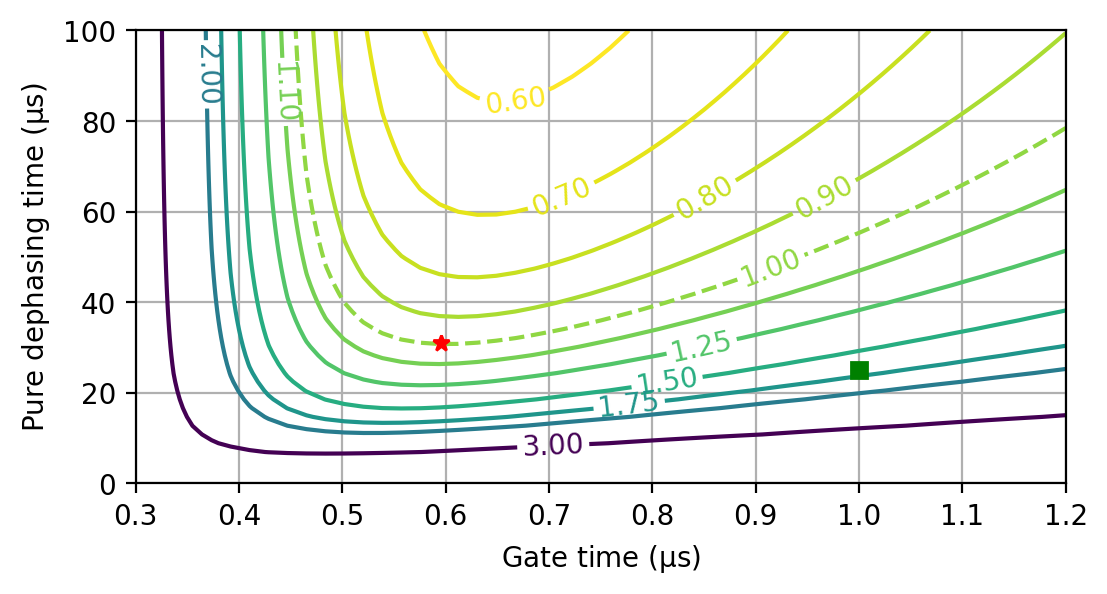
One approach to fault-tolerant quantum computing would be to implement surface code [34] via bosonic qubits. Thus, an intriguing question emerges: how long should the coherence time of a bosonic qubit be in order to achieve the surface code threshold at [35]? According to Eq.(12) and for the coherence times used in the simulations in Fig. 2, the pure dephasing channel of the transmon is the dominant source of gate errors. By sweeping the gate time and pure dephasing time, a gate error becomes possible if (Fig. 5). In addition, , , , and gate errors require even longer pure dephasing times of , , , and , respectively. Although increasing the dispersive coupling strength enables faster operations and thus reduces gate errors, it comes at the cost of unwanted nonlinearities, such as the self-Kerr interaction [36].
6.2 Optimization Algorithms with Decoherence Effects
The results of the numerical evaluation of the error susceptibility naturally suggests two modifications to the optimization algorithm that will lower the gate errors by including the effects of decoherence in the optimization. Here, our gate synthesis is composed of two steps: gate optimization in a closed system (without decoherence) and a realistic evaluation in an open system (with decoherence), as the latter requires greater computational complexity. Although previous studies have shown that open-system optimizations yield smaller gate errors [37, 30, 38], in practice this is difficult to achieve for bosonic qubits owing to their large system dimensions. For example, the optimization in this study with the Schrödinger equation was conducted with dimensions (i.e., for transmon and cavity, respectively). Replacing it with the Lindblad equation would naively require dimensions, making it computationally exorbitant.
The insight offered by this study is that the effect of the cavity photon loss on the gate errors can be predicted from the cavity lifetime, the mean photon number of the code, and the gate time. Consequently, we propose a hybrid approach consisting of the Lindblad equation for the transmon and the Schrödinger equation for the cavity, which enables optimization that integrates the decoherence channels of bosonic qubits. Such a half-open system would require only dimensions, a significant reduction in computational complexity.
Although this half-open approach is tailored for bosonic qubits, the results of this study also support a closed approach that can suppress the numerical cost in general quantum systems. Specifically, if the error susceptibility is directly included in the cost function, this will permit gate optimizations with decoherence effects requiring only dimensions. Unfortunately, the GRAPE algorithm is unable to calculate error susceptibility as quantities that depend on intermediate states require a computationally complex gradient calculation. However, a recent study has shown that a backpropagation-based algorithm can enable an efficient gradient calculation of such quantities [39]. The error susceptibility can be included in the backpropagation network, and thus, a quantum optimal control with decoherence effects can be realized for any quantum system.
7 Conclusion
A bosonic qubit in a superconducting circuit with optimally controlled gates offers an attractive approach to quantum computing. However, a detailed numerical model incorporating all the decoherence channels that limit the gate fidelities in such a system has remained elusive. In this work, the performance of a bosonic qubit was modeled with numerical simulations, which yielded an analytical formulation that encapsulates decoherence effects from the cavity and the ancilla transmon constituting the superconducting circuit. The analysis permitted a quantitative evaluation of decoherence-induced gate errors on the bosonic qubit. By approximating the achievable gate error of the Hadamard gate on the Bin(1,1)-encoded bosonic qubit, it was found that a gate error of is possible by reducing pure dephasing in the transmon. Moreover, the contribution of the cavity photon loss to the gate error is insensitive to the details of the gate operation. This insight and our error model suggest alternative optimization algorithms that can handle decoherence at modest numerical costs.
Author Contributions
K.M. prepared the program codes, conducted the numerical experiments, conceived the gate error model, analyzed all of the data, and wrote the manuscript. T.T., I.M., and S.S. contributed to the discussions. All authors contributed to refining the manuscript.
Data Availability
The data that support the findings of this study are available from the corresponding author upon reasonable request.
References
References
- [1] Joshi A, Noh K and Gao Y Y 2021 Quantum Science and Technology 6 033001 URL https://doi.org/10.1088/2058-9565/abe989
- [2] Ofek N, Petrenko A, Heeres R, Reinhold P, Leghtas Z, Vlastakis B, Liu Y, Frunzio L, Girvin S M, Jiang L, Mirrahimi M, Devoret M H and Schoelkopf R J 2016 Nature 536 441–445 URL https://doi.org/10.1038/nature18949
- [3] Reagor M, Paik H, Catelani G, Sun L, Axline C, Holland E, Pop I M, Masluk N A, Brecht T, Frunzio L, Devoret M H, Glazman L and Schoelkopf R J 2013 Applied Physics Letters 102 192604 URL https://aip.scitation.org/doi/10.1063/1.4807015
- [4] Reagor M, Pfaff W, Axline C, Heeres R W, Ofek N, Sliwa K, Holland E, Wang C, Blumoff J, Chou K, Hatridge M J, Frunzio L, Devoret M H, Jiang L and Schoelkopf R J 2016 Physical Review B 94 014506 URL https://link.aps.org/doi/10.1103/PhysRevB.94.014506
- [5] Michael M H, Silveri M, Brierley R T, Albert V V, Salmilehto J, Jiang L and Girvin S M 2016 Physical Review X 6 031006 URL https://doi.org/10.1103/PhysRevX.6.031006
- [6] Ma W L, Puri S, Schoelkopf R J, Devoret M H, Girvin S and Jiang L 2021 Science Bulletin 66 1789–1805 URL https://doi.org/10.1016/j.scib.2021.05.024
- [7] Leghtas Z, Kirchmair G, Vlastakis B, Devoret M H, Schoelkopf R J and Mirrahimi M 2013 Physical Review A 87 042315 URL https://doi.org/10.1103/PhysRevA.87.042315
- [8] Heeres R W, Reinhold P, Ofek N, Frunzio L, Jiang L, Devoret M H and Schoelkopf R J 2017 Nature Communications 8 94 URL https://doi.org/10.1038/s41467-017-00045-1
- [9] Reinhold P, Rosenblum S, Ma W L, Frunzio L, Jiang L and Schoelkopf R J 2020 Nature Physics 16 822–826 URL https://www.nature.com/articles/s41567-020-0931-8
- [10] Ma Y, Xu Y, Mu X, Cai W, Hu L, Wang W, Pan X, Wang H, Song Y P, Zou C L and Sun L 2020 Nature Physics 16 827–831 URL https://www.nature.com/articles/s41567-020-0893-x
- [11] Sun L, Petrenko A, Leghtas Z, Vlastakis B, Kirchmair G, Sliwa K M, Narla A, Hatridge M, Shankar S, Blumoff J, Frunzio L, Mirrahimi M, Devoret M H and Schoelkopf R J 2014 Nature 511 444–448 URL https://www.nature.com/articles/nature13436
- [12] Rosenblum S, Reinhold P, Mirrahimi M, Jiang L, Frunzio L and Schoelkopf R J 2018 Science 361 266–270 URL https://science.sciencemag.org/content/361/6399/266
- [13] Hu L, Ma Y, Cai W, Mu X, Xu Y, Wang W, Wu Y, Wang H, Song Y P, Zou C L, Girvin S M, Duan L M and Sun L 2019 Nature Physics 15 503–508 URL https://doi.org/10.1038/s41567-018-0414-3
- [14] Gertler J M, Baker B, Li J, Shirol S, Koch J and Wang C 2021 Nature 590 243–248 URL https://www.nature.com/articles/s41586-021-03257-0
- [15] Wang C, Gao Y Y, Reinhold P, Heeres R W, Ofek N, Chou K, Axline C, Reagor M, Blumoff J, Sliwa K M, Frunzio L, Girvin S M, Jiang L, Mirrahimi M, Devoret M H and Schoelkopf R J 2016 Science 352 1087–1091 URL https://science.sciencemag.org/content/352/6289/1087
- [16] Gao Y Y, Lester B J, Zhang Y, Wang C, Rosenblum S, Frunzio L, Jiang L, Girvin S M and Schoelkopf R J 2018 Physical Review X 8 021073 URL https://link.aps.org/doi/10.1103/PhysRevX.8.021073
- [17] Gao Y Y, Lester B J, Chou K S, Frunzio L, Devoret M H, Jiang L, Girvin S M and Schoelkopf R J 2019 Nature 566 509–512 URL https://www.nature.com/articles/s41586-019-0970-4
- [18] Vlastakis B, Kirchmair G, Leghtas Z, Nigg S E, Frunzio L, Girvin S M, Mirrahimi M, Devoret M H and Schoelkopf R J 2013 Science 342 607–610 URL https://doi.org/10.1126/science.1243289
- [19] Glaser S J, Boscain U, Calarco T, Koch C P, Köckenberger W, Kosloff R, Kuprov I, Luy B, Schirmer S, Schulte-Herbrüggen T, Sugny D and Wilhelm F K 2015 The European Physical Journal D 69 279 URL https://doi.org/10.1140/epjd/e2015-60464-1
- [20] Gottesman D, Kitaev A and Preskill J 2001 Physical Review A 64 012310 URL https://link.aps.org/doi/10.1103/PhysRevA.64.012310
- [21] Mirrahimi M, Leghtas Z, Albert V V, Touzard S, Schoelkopf R J, Jiang L and Devoret M H 2014 New Journal of Physics 16 045014 URL https://doi.org/10.1088/1367-2630/16/4/045014
- [22] Albert V V, Noh K, Duivenvoorden K, Young D J, Brierley R T, Reinhold P, Vuillot C, Li L, Shen C, Girvin S M, Terhal B M and Jiang L 2018 Physical Review A 97 032346 URL https://link.aps.org/doi/10.1103/PhysRevA.97.032346
- [23] Grimsmo A L, Combes J and Baragiola B Q 2020 Physical Review X 10 011058 URL https://link.aps.org/doi/10.1103/PhysRevX.10.011058
- [24] Li L, Young D J, Albert V V, Noh K, Zou C L and Jiang L 2021 Physical Review A 103 062427 URL https://link.aps.org/doi/10.1103/PhysRevA.103.062427
- [25] Koch J, Yu T M, Gambetta J, Houck A A, Schuster D I, Majer J, Blais A, Devoret M H, Girvin S M and Schoelkopf R J 2007 Physical Review A 76 042319 URL https://link.aps.org/doi/10.1103/PhysRevA.76.042319
- [26] Krastanov S, Albert V V, Shen C, Zou C L, Heeres R W, Vlastakis B, Schoelkopf R J and Jiang L 2015 Physical Review A 92 040303 URL https://doi.org/10.1103/PhysRevA.92.040303
- [27] Heeres R W, Vlastakis B, Holland E, Krastanov S, Albert V V, Frunzio L, Jiang L and Schoelkopf R J 2015 Physical Review Letters 115 137002 URL https://doi.org/10.1103/PhysRevLett.115.137002
- [28] Khaneja N, Reiss T, Kehlet C, Schulte-Herbrüggen T and Glaser S J 2005 Journal of Magnetic Resonance 172 296–305 URL https://doi.org/10.1016/j.jmr.2004.11.004
- [29] de Fouquieres P, Schirmer S G, Glaser S J and Kuprov I 2011 Journal of Magnetic Resonance 212 412–417 URL https://www.sciencedirect.com/science/article/pii/S1090780711002552
- [30] Schulte-Herbrüggen T, Spörl A, Khaneja N and Glaser S J 2011 Journal of Physics B: Atomic, Molecular and Optical Physics 44 154013 URL https://iopscience.iop.org/article/10.1088/0953-4075/44/15/154013
- [31] Nielsen M A and Chuang I L 2011 Quantum Computation and Quantum Information: 10th Anniversary Edition 10th ed (Cambridge University Press)
- [32] O’Malley P J J, Kelly J, Barends R, Campbell B, Chen Y, Chen Z, Chiaro B, Dunsworth A, Fowler A G, Hoi I C, Jeffrey E, Megrant A, Mutus J, Neill C, Quintana C, Roushan P, Sank D, Vainsencher A, Wenner J, White T C, Korotkov A N, Cleland A N and Martinis J M 2015 Physical Review Applied 3 044009 URL https://link.aps.org/doi/10.1103/PhysRevApplied.3.044009
- [33] Eickbusch A, Sivak V, Ding A Z, Elder S S, Jha S R, Venkatraman J, Royer B, Girvin S M, Schoelkopf R J and Devoret M H 2022 Nature Physics URL https://doi.org/10.1038/s41567-022-01776-9
- [34] Fowler A G, Mariantoni M, Martinis J M and Cleland A N 2012 Physical Review A 86 032324 URL https://doi.org/10.1103/PhysRevA.86.032324
- [35] Barends R, Kelly J, Megrant A, Veitia A, Sank D, Jeffrey E, White T C, Mutus J, Fowler A G, Campbell B, Chen Y, Chen Z, Chiaro B, Dunsworth A, Neill C, O’Malley P, Roushan P, Vainsencher A, Wenner J, Korotkov A N, Cleland A N and Martinis J M 2014 Nature 508 500–503 URL https://www.nature.com/articles/nature13171
- [36] Nigg S E, Paik H, Vlastakis B, Kirchmair G, Shankar S, Frunzio L, Devoret M H, Schoelkopf R J and Girvin S M 2012 Physical Review Letters 108 240502 URL https://link.aps.org/doi/10.1103/PhysRevLett.108.240502
- [37] Rebentrost P, Serban I, Schulte-Herbrüggen T and Wilhelm F K 2009 Physical Review Letters 102 090401 URL https://link.aps.org/doi/10.1103/PhysRevLett.102.090401
- [38] Goerz M H, Reich D M and Koch C P 2014 New Journal of Physics 16 055012 URL https://iopscience.iop.org/article/10.1088/1367-2630/16/5/055012
- [39] Leung N, Abdelhafez M, Koch J and Schuster D 2017 Physical Review A 95 042318 URL https://link.aps.org/doi/10.1103/PhysRevA.95.042318
- [40] Motzoi F, Gambetta J M, Merkel S T and Wilhelm F K 2011 Physical Review A 84 022307 URL https://link.aps.org/doi/10.1103/PhysRevA.84.022307
- [41] Slepian D 1978 The Bell System Technical Journal 57 1371–1430
- [42] Virtanen P, Gommers R, Oliphant T E, Haberland M, Reddy T, Cournapeau D, Burovski E, Peterson P, Weckesser W, Bright J, van der Walt S J, Brett M, Wilson J, Millman K J, Mayorov N, Nelson A R J, Jones E, Kern R, Larson E, Carey C J, Polat İ, Feng Y, Moore E W, VanderPlas J, Laxalde D, Perktold J, Cimrman R, Henriksen I, Quintero E A, Harris C R, Archibald A M, Ribeiro A H, Pedregosa F, van Mulbregt P and SciPy 10 Contributors 2020 Nature Methods 17 261–272 URL https://www.nature.com/articles/s41592-019-0686-2
- [43] Johansson J R, Nation P D and Nori F 2012 Computer Physics Communications 183 1760–1772 URL https://www.sciencedirect.com/science/article/pii/S0010465512000835
Appendix A Definitions
A.1 Fidelities and Gate Errors
We calculate the fidelity between two quantum states and by using the following equation:
| (13) |
The average gate fidelity between and a quantum process is calculated as follows:
| (14) |
where is an average on a logical Bloch sphere. The gate error of is evaluated as .
A.2 Codewords and Operations
Let and be logical codewords of a bosonic code. After a photon loss error happens, the codeword jumps to a corresponding error word for . The Bin(1,1) code (mean photon number ) corresponds to
| (15) | |||
| (16) |
The Bin(2,2) code () corresponds to
| (17) | |||
| (18) |
The 4-leg cat code corresponds to
| (19) | |||||
| (20) |
where are normalization factors to ensure . The mean photon number is approximately .
A gate unitary corresponding to a logical gate operation is a Pauli operator on the logical codewords, such as:
| (21) | |||||
| (22) |
where is the identity operator of the transmon. Note that the transmon remains in the ground state before and after the operation. An error recovery gate is a unitary operator obeying the following equation:
| (23) |
where and are complex numbers satisfying .
Appendix B Details of the Calculation
B.1 Gate Optimization
The system Hamiltonian is
| (24) | |||
| (25) | |||
| (26) |
Higher order interactions such as the self-Kerr interaction were ignored in this study. The control Hamiltonian has four time-dependent terms: (the transmon drive and the cavity displacement) (in- and quadrature-phase components). The four control amplitudes and were optimized. The gate time is discretized into time steps. The system Hamiltonian at the -th time step can be written in a generalized form,
| (27) |
where and are labels for time steps and controls, respectively. The total unitary is given by
| (28) | |||||
| (29) |
Note that we use natural units of .
The cost function of the optimization includes a gate error and amplitude penalties. The gate error can be calculated in terms of the Hilbert–Schmidt distance:
| (30) |
where is the dimension of the code, and is the projection operator to the codespace [40]. Multiplying the projection operations prevents leakage out of the codespace. The global phase of this gate was ignored in the optimization. The GRAPE algorithm [28] enables fast evaluations to be made of the cost gradients of the gate error, .
The number of dimensions in the gate optimization was 60 (2 for the transmon 30 for the cavity). Note that ignoring the second excited state of the transmon has negligible effect. Although, in principle, a cavity mode is a harmonic oscillator of infinite dimension, the cavity dimensions can be truncated for numerical computations. Here, amplitude penalties are given to suppress occupations of higher photon states during the gate to avoid truncation-related effects. A nonlinear amplitude penalty was used instead of a simple quadratic penalty:
| (31) |
This penalty softly clips the amplitudes at .
The time-dependent amplitudes were parameterized with degrees of freedom for each control in the frequency domain:
| (32) | |||
| (33) |
where corresponds to the maximum bandwidth. was set to a number large enough to ensure a sufficient degree of freedom of according to signal processing theory [41].
To ensure that the waveforms would be within the desired bandwidth, amplitude penalties were added at time boundaries:
| (34) |
This penalty makes the waveforms start and end smoothly.
The cost function is a weighted sum of the above penalties , and the coefficients were determined empirically. The total number of optimization parameters is , typically being a few hundred. We started an optimization with random initial parameters and sequentially updated the parameters to minimize the cost function with a limited-memory Broyden–Fletcher–Goldfarb–Shanno algorithm [42].
B.2 Evaluation of Gate Error
The quantum state dynamics with gate operations obeying the Schrödinger or the Lindblad equation were calculated by QuTiP [43]. The Lindblad equation included cavity photon loss, transmon relaxation, transmon pure dephasing, and transmon thermal excitation. Since Eq.(14) includes an integral, we computed the gate fidelity as an average:
| (35) |
where corresponds to the initial state of the cavity. is one of the six representative points of the logical Bloch sphere,
| (36) |
B.3 Example of Optimized Gates
Fig. 6 shows examples of control waveforms that implement the Hadamard gate for the Bin(1,1) code. The waveforms were generated with different initial parameters. Although both yield the Hadamard gate operation, their waveforms are completely different from each other, and the resultant intermediate states are also different.

Appendix C Gate Error Model for Arbitrary Operations
C.1 Details of Gate Error Model
This section derives a gate error model from the Lindblad equation. Let be a time-dependent Hamiltonian realizing the desired unitary . Without decoherence, the system dynamics can be written by the Schrödinger equation with , where is the unitary propagator from to , and corresponds to the initial state of the system. With decoherence included, the system dynamics obey the Lindblad equation , where , , and respectively correspond to an intermediate state, rate of decoherence, and a jump operator representing the decoherence. The intermediate state is , where is a quantum process from to . To consider the decoherence effect, we compare the two dynamics and in a small time step . Starting from time and the state , the state fidelity between the two states at with and without the decoherence is given by
| (37) |
In accordance with the Schrödinger and Lindblad equations, we can replace and , where we use for simplicity. A small error induced by decoherence in the small time is expressed as
| (38) | |||||
| (39) |
up to first order in . Next, we define the error probability , unnormalized fidelity , and error susceptibility at with a dependence on the initial state:
| (40) | |||||
| (41) | |||||
| (42) |
According to the definition, corresponds to the probability that the error occurs at . Note that where denotes a state vector after the error occurs at . corresponds to the product of the error probability and the fidelity between states before and after the error occurs; thus, we refer to as the unnormalized fidelity.
In order to encapsulate the decoherence effect, we average out the dependences on time and initial states and define the error susceptibility of the gate by
| (43) |
where is an average on the logical Bloch sphere (namely, averaging where and ). and are defined in the same fashion. From Eq.(39), (42), and (43), the decoherence-induced gate error can be written as
| (44) | |||||
| (45) |
This model can be easily extended to multiple decoherence cases. By extending the Lindblad equation to a multiple decoherence case, , Eq.(45) is modified to
| (46) |
Namely, the gate error is expressed as a weighted sum of all the decoherence channels.
In numerical evaluations of error susceptibility, the integral of initial states is replaced to an average in the same manner as for gate errors (Eq.(35)).
C.2 Comparison of the Gate Error Model and Lindblad Simulations
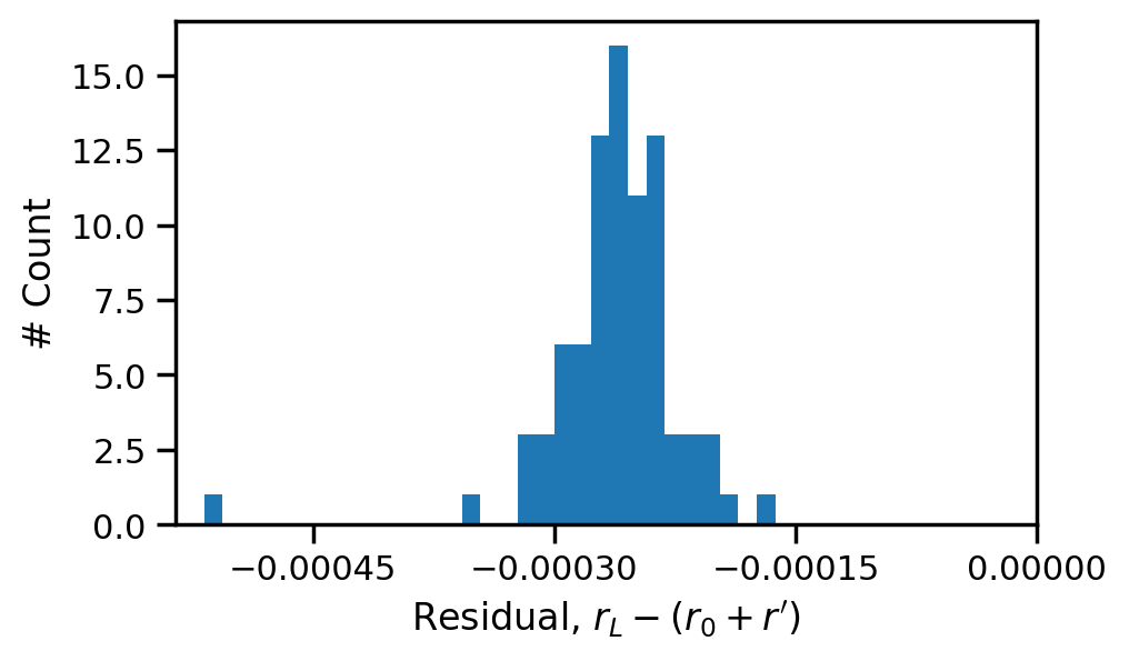
We will validate the gate error model by comparing it with the Lindblad equation for the gates investigated in Fig. 4. Total errors can be decomposed into intrinsic errors , which can be evaluated by solving the Schrödinger equation, and decoherence-induced errors , which can be estimated by Eq.(9). Let be a total error evaluated by the Lindblad equation, which will satisfy if our error model properly captures the contributions of the given decoherences. Fig. 7 shows a histogram of residual . Since the residuals are small, the proposed model can quantitatively capture the decoherence effects on gate errors. Although a small bias remains, it is negligible when compared to the total errors of a few percent. The first-order approximation in our model could yield this bias.
C.3 Effect of the Photon Loss Channel
As described in the main text, for the photon loss is close to the mean photon number for bosonic qubits. In this section, we prove that exactly equals for a simpler system, a cavity mode that is driven by a displacement pulse.
Firstly, for the photon loss is conserved under displacement. Let be an arbitrary cavity state, and consider a displacement drive , where . The error susceptibility at is
| (47) |
The first and second terms correspond to and , respectively (Eq.(42)). They can be transformed as follows:
| (48) | |||||
| (49) |
where was used, and the leftmost terms correspond to and . The error probability is increased by the displacement, but concurrently the photon distribution becomes wider, resulting in an enlarged unnormalized fidelity . Each increment is given by the three rightmost terms in Eq.(48) and (49), and they are identical. Thus, the error susceptibility for the cavity photon loss is a conserved quantity under displacement drives: .
Secondly, equals the mean photon number of because . Let us limit the initial state to the codespace: with . Such states satisfy because the codewords have the same mean photon number. The states also satisfy because the codewords and errorwords are orthogonal: . Thus, the error susceptibility at equals the mean photon number of the code: .
Consequently, is always satisfied for cavity modes. Note that we considered a single harmonic oscillator, and coupling to the ancilla transmon violates the relationship. Although it emerges as the distribution in Fig. 4(c, green), the deviations are not large for the optimized gates used in the analyses.
C.4 Coherence Limit of Idle Gate Error
A coherence limit of an idle gate (just waiting a duration ) on a two level system is given by
| (50) |
where and correspond to the relaxation time and pure dephasing time, respectively. This equation is equivalent to Eq.(3) in Ref. [32] by assuming that the dephasing is like white noise. Here, we derive this equation from our gate error model. Let be the initial state, and note that this state does not change in time without decoherence.
For the relaxation, the jump operator is . The error susceptibility with state dependence is . Integrating over the Bloch sphere gives the following:
| (51) |
For the pure dephasing, the jump operation is . The error susceptibility with state dependence is . Integrating over the Bloch sphere gives the following:
| (52) |
Thus, we have reproduced Eq.(50) with our model.
C.5 Standard Deviations of Transmon Relaxation and Dephasing
This section shows that in a simple case. Let us assume that a transmon state uniformly distributes on a Bloch sphere. According to ,
| (53) | |||||
| (54) | |||||
| (55) |
Thus we got and . Although the statistical distribution of was not uniform (note that the horizontal positions of the blue dots in Fig. 4(c) correspond to the average of transmon excitation: ), this relationship could be satisfied because .
Appendix D Gate Errors for Other Gates
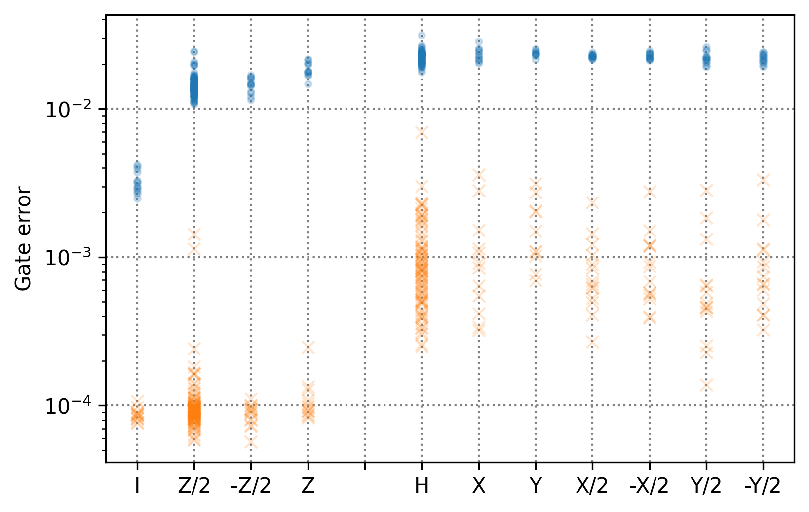
Gate operations on bosonic qubits are classified into two groups: (1) phase gates that preserve the photon distributions and (2) other gates that change the photon distribution. Fig. 8 shows the gate dependence of the gate errors for the Bin(1,1) code. It indicates that phase gates generally exhibit lower gate errors. The gate time was fixed to , and several gates were optimized with different initial parameters, resulting in the vertical distributions. The decoherence rates used in this section were same to the rates used in Fig. 2
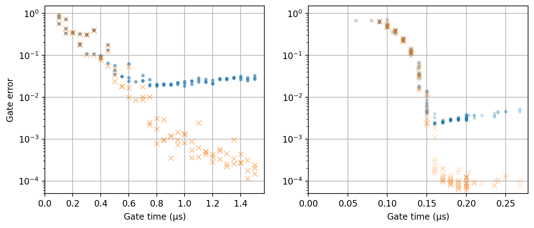
As well as the difference in errors with the specific gate time, the two groups exhibit different dependencies on gate times. By comparing with a fixed gate time, the Hadamard gates exhibit larger errors than the gates (Fig. 9). Note that the saturation behavior of the gate around originates from the optimization terminating when the gate error fell below .
Appendix E Gate Errors with Other Encodings
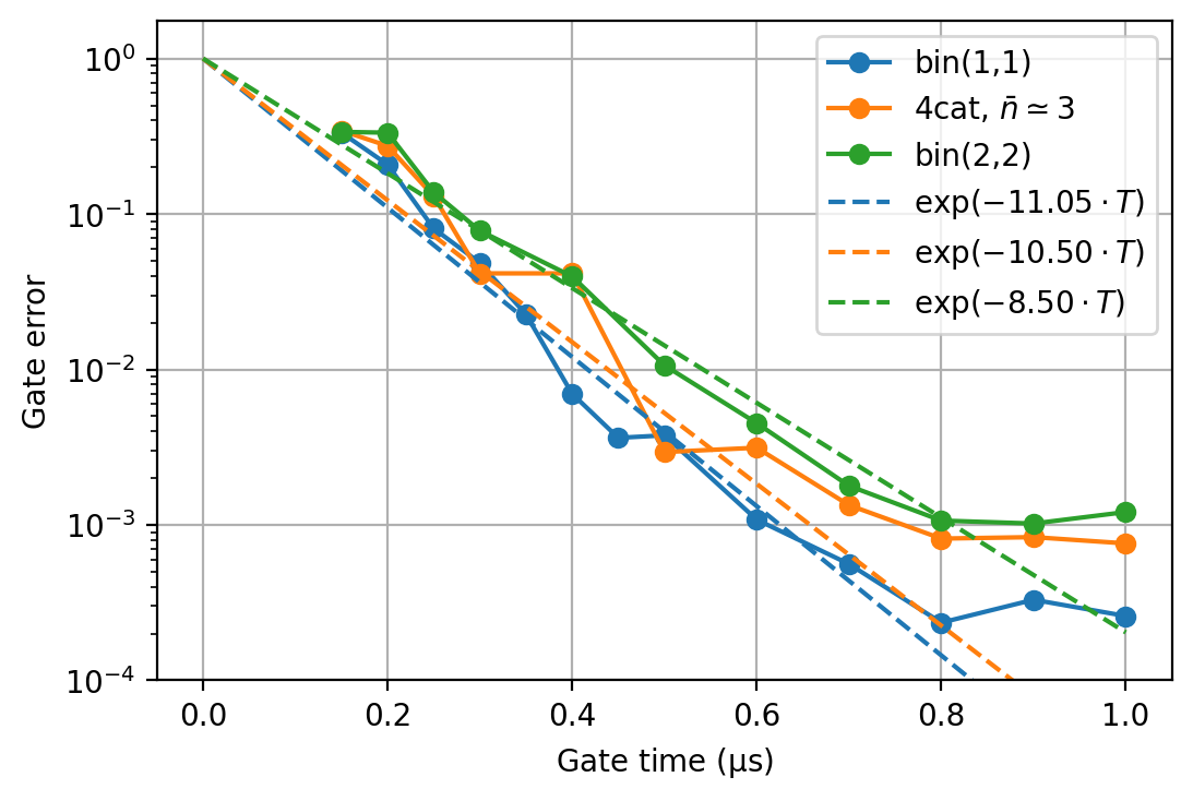
In this section, we compare the Bin(1,1) and other encodings (the 4-leg cat and Bin(2,2), see A.2) to provide similar analyses in Section 6.1. The cat size was , and the mean photon number of the 4-leg cat was . To obtain gate-time dependence of intrinsic gate errors, Hadamard gates for each encodings were generated by numerical optimization with several gate times (Fig. 10). We fitted the gate errors by an empirical equation with for the Bin(1,1), for the 4-leg cat, and for the Bin(2,2) code. Note that weaker constraints (B.1), namely a larger amplitude and wider bandwidth, were used in these optimizations. The speed of the gate operation should be limited by the dispersive interaction when the strength and bandwidth of the waveforms are sufficient. The aim of using weaker constraints is to ensure that intrinsic errors are limited mainly due to the dispersive interaction, not constraints in optimization.
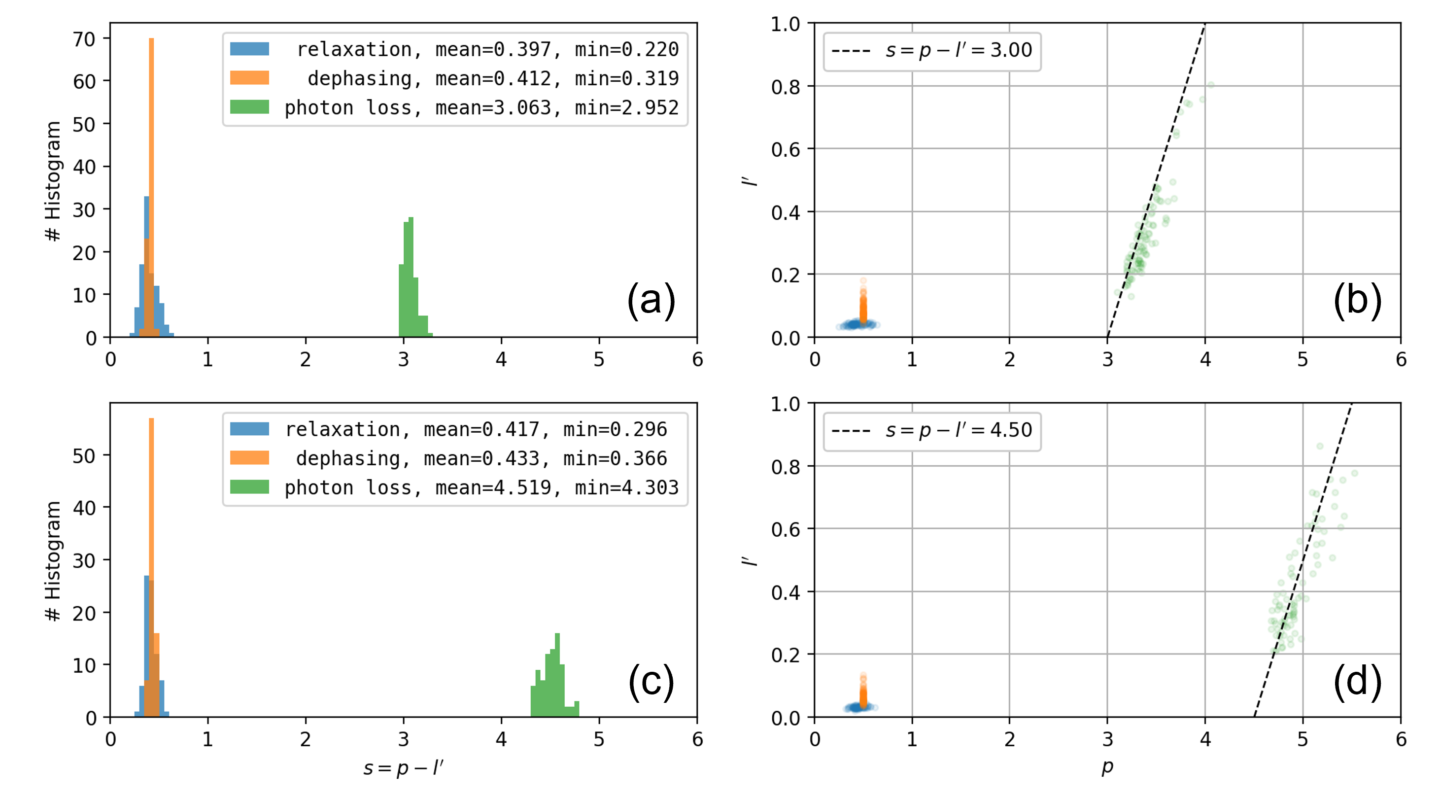
Fig. 11 shows the error susceptibilities of Hadamard gates for the 4-leg cat and Bin(2,2) code. The gate time was fixed to . The codewords are different, but the error susceptibilities exhibit a similar statistics to that of the Bin(1,1) code; namely around 0.3 for transmon relaxation and dephasing, and around for cavity photon loss.
As in Section 6.1 in the main text, we can provide rough estimations of the achievable gate errors for these encodings:
| (56) |
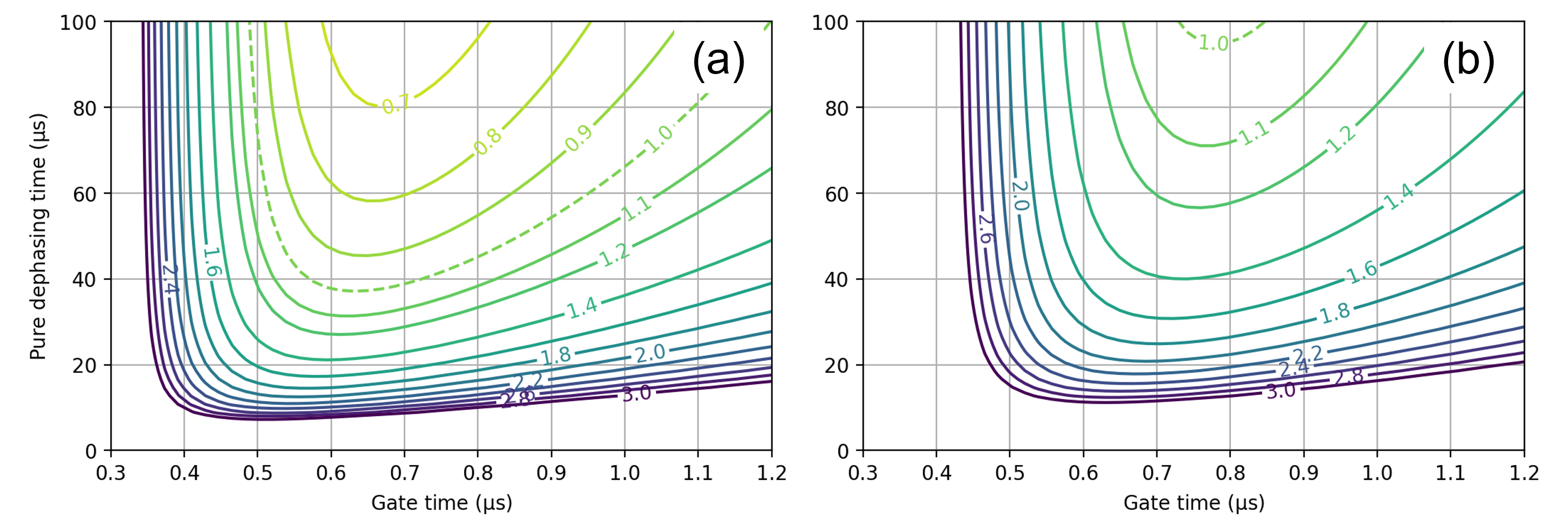
The minimum error susceptibilities are shown in the legend of Fig. 11. Fig. 12 shows the approximate gate errors as calculated by Eq.(56) as functions of the transmon dephasing time and gate time.
Appendix F Error Susceptibility for the Recovery Gate
Figure 13 shows the error susceptibility for recovery gates (Eq.(23)) for the Bin(1,1) code. The gate time was fixed to . This operation is not a logical gate, but exhibits similar statistics to that of the Hadamard gate.

Appendix G Error Susceptibility with Stronger Displacement
To investigate the error susceptibility statistics for optimized gates with stronger displacements, we generated several Hadamard gates on Bin(1,1) with the weaker constraint (see B.1). Fig. 14 shows the resulting error susceptibilities. The gate time was fixed to . Note that corresponds to the mean photon number during the gate, and thus the displacement strength is indicated as the horizontal position of the green dots in the right panel. Stronger displacement pulses lead to intermediate states with higher photon number states and a higher probability of photon loss, but the figure shows that the error susceptibility is close to the mean photon number. Thus, the contribution of the cavity photon loss channel does not depend on the displacement strength.

Appendix H Gate-time Dependence of Error Susceptibility
Since the error susceptibility depends on the gate time, it was further investigated for the Hadamard gate for the Bin(1,1) code (Fig. 15). It was found that longer gates ( and ) exhibited similar error susceptibilities while a short gate () exhibits a tendency to increase error susceptibility. Decoherence-induced errors for short gates are negligible because the intrinsic errors are dominant, and thus the weak gate-time dependence of the error susceptibility can be ignored in this regime. We assume that error susceptibility is constant in the horizontal range of Fig. 5 in order to simplify equations like Eq.(12).
