ELECTRONICS AND SENSOR SUBSYSTEM DESIGN FOR DAEDALUS 2 ON REXUS 29: AN AUTOROTATION PROBE FOR SUB-ORBITAL RE-ENTRY
Abstract
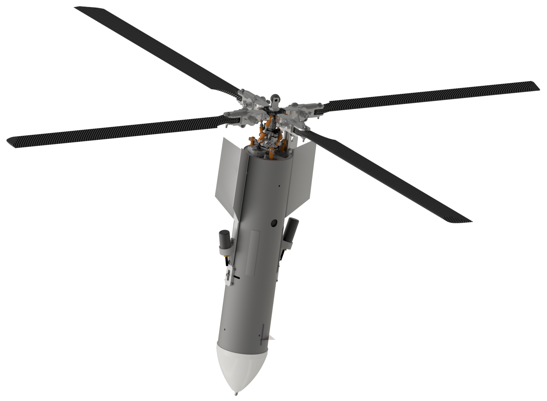
The Daedalus 2 mission aboard REXUS 29 is a technology demonstrator for an alternative descent mechanism for very high altitude drops based on auto-rotation. It consists of two probes that are ejected from a sounding rocket at an altitude of about and decelerate to a soft landing using only a passive rotor with pitch control.
This type of autonomous, scientific experiment poses great challenges upon the electronics subsystem, which include mechanical stress, power system reliability, sensor redundancy, subsystem communication, and development procedures.
Based on the data gathered in Daedalus 1 [1] multiple new approaches were developed to fulfill these requirements, such as redundant communication links, mechanical decoupling of PCBs and fault-tolerant power source selection.
keywords:
Robust Electronics, Re-Entry, Autorotation, REXUS 291 Introduction
The experiment will fly as a payload on an Improved Orion sounding rocket as part of the REXUS/BEXUS program and will test a novel form of re-entry and descent control without parachutes, adding to the knowledge base of rotors in space applications, especially regarding the descent of interplanetary probes.
The use of autorotation has already been conceptually demonstrated by the predecessor project Daedalus 1, which operated completely passively. In contrast, Daedalus 2 decouples the rotor from the main body and uses an active control system for sink rate and rotor rotation speed by changing the pitch of the rotor blades, which poses great challenges for the electronics and software implementation.
The implementation details of the mechanical setup, with focus on the complex blade tilting mechanism, were already covered in [2].
2 System Topology
The Daedalus 2 experiment consists, as most space missions do, of a space, a ground and a user segment. The user segment covers post-flight data analysis and will not be covered here in detail. It receives the recorded and recovered data after the flight from the ground segment. A schematic overview of the space and ground segment is presented in Fig. 2.
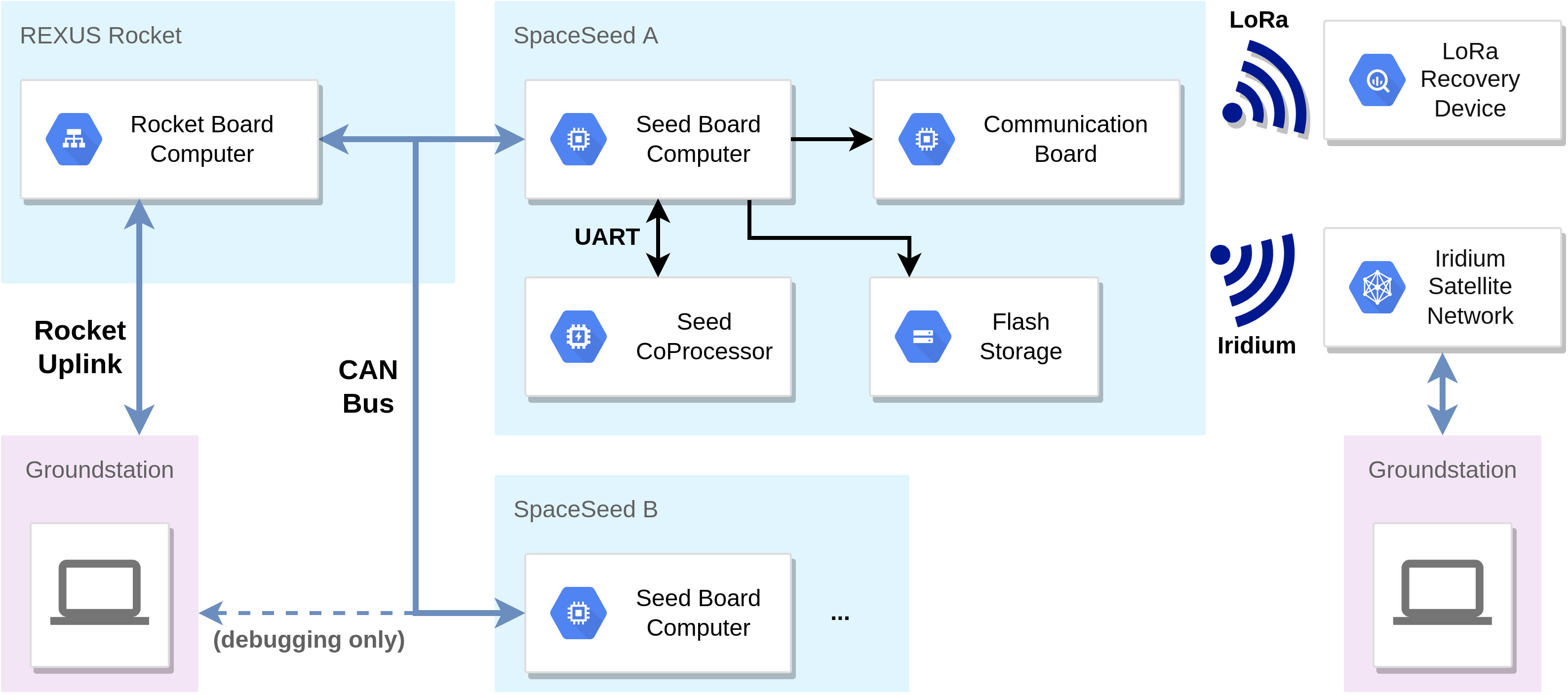
The rocket board computer (RBC) and the Spaceseeds with their Seed Board Computers (SBC) and CoProcessors (COP) form the space segment. The RBC remains on the REXUS rocket for the whole duration of the flight. Its main tasks are power control for the Spaceseeds (see Sec. 3.4) as well as telecommand and telemetry forwarding between the REXUS rocket uplink provided by the REXUS service module and the Spaceseeds (further discussed in Sec. 4.2).
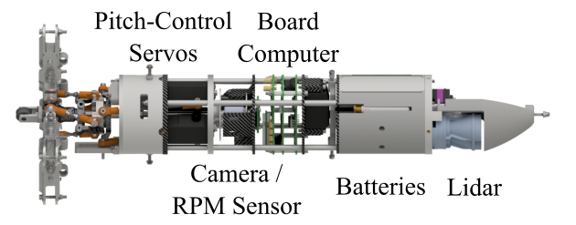
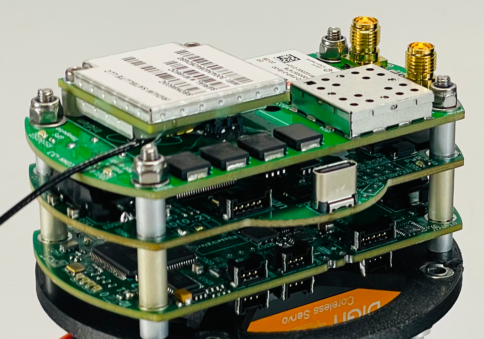
The two Spaceseeds are the free-falling units (FFU) that will be ejected at trajectory apex of roughly , autonomously control their descent and landing and will then later be recovered to extract the detailed protocol stored on the redundant on-board flash storage. (The ejection is timed by the REXUS service module and is therefore not a task of either of our systems.) A Spaceseed has two CPUs, the SBC and the COP. The SBC is the main computing unit responsible for data acquisition, communication, the flight controller and data logging; the COP is responsible for interfacing with additional periphery, such as power and thermal management. This split allowed software development to be more focused on their respective sub-task and made it possible to develop two separate electronic boards which can undergo development revisions independently, thus a multi-board design for the board computer allowed for much faster design iterations while also helping to work around space constraints.
The ground segment consists of our ground station which interfaces with the uplink to the REXUS service module, the Iridium network for receiving direct downlinks from the Seeds and a recovery device which helps locate the landed seeds, which interfaces via LoRa. It collects and displays the received data and allows commanding the system before ejection. Displaying live data is important as the FFU’s GPS position is required for successful recovery.
3 Electronics
3.1 Mechanical Challanges
As a rough outline for maximum accelerations we build on the experience from Daedalus 1, where one of the three probes experienced forces in excess of over . This occurred because the Spaceseed entered flat spin, a flight configuration where the main body is not oriented vertical as planned but horizontal, while rapidly spinning around the z-axis.
And although the new flight controller should prevent another flat spin, the system should still be robust against such situations. Together with the accelerations and vibrations on board the rocket and later during atmospheric entry, this results in extreme mechanical stresses for all components and especially connectors are at a high risk of loose contacts or complete failure.
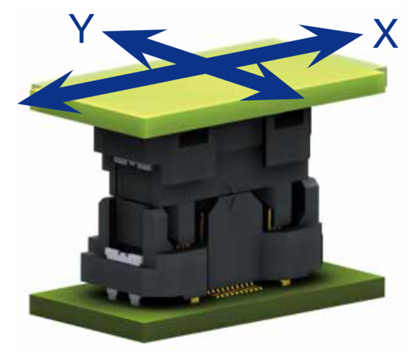
FX23L Connection [3]
For mechanical robustness it was chosen to use a special construction technique with mechanically decoupled connectors to build a robust multi-board flight computer. Specifically Hirose FX23L connectors have the ability to float, i.e. to still make shock- and vibration-proof connections, even if misaligned by as much as (see Fig. 4).
Additionally, each solder connection of wires to PCBs uses two solder holes and a mechanical hole to provide stress relief.
3.2 Redundant Sensor Configuration
The maximum acceleration during the Daedalus 1 flat spin could not be determined as the measurement surpassed the maximum value of that the accelerometer could measure. That is why Daedalus 2 carries two accelerometers per Spaceseed, where the first is quite precise and used as input for the flight controller while a second high-load accelerometer provides measurements up to and could also be useful as a second reference during result analysis.
A second critical sensor is the barometer because it is the main reference for determining both height and vertical speed, as GPS won’t be available in high altitudes. Again two sensors are used, where the first obtains a precise accuracy of over the range from while the second has lower accuracy but can reach down to , which is useful because much of the flight is performed in very low atmosphere.
3.3 Battery Choice
The battery chemistry chosen for the experiment is \chLi/SO2, specifically SAFT primary cells of type LO 35 SX, because of their non-flammability, big temperature range, high peak current and the excellent energy density.
| Self-Discharge | |
|---|---|
| Storage Temperature | |
| Operating Temperature | |
| Capacity | |
| Voltage (at and ) | |
| Current (cont) | |
| Current (peak) | |
| Weight | |
| Energy Density |
The cells are employed in a 3S2P configuration, leading to a nominal voltage of at a capacity of . For redundancy purposes each individual battery strings should suffice for a successful mission. In the case of failure of a single string it will be automatically disconnected using the circuit described in Sec. 3.4.
3.4 Power Topology
The Spaceseeds can be powered from via three inputs. Two inputs are used for the batteries, while the third is supplied by the Rocket Board Computer which relays the supply from the REXUS Service Module (RXSM).
Upon Spaceseed ejection the RXSM connection is severed and the experiment shall seamlessly switch from the external power supply to the internal batteries. In its simplest form this can be achieved with diode OR-ing, where each supply has a Schottky diode, such that the highest supply voltage will always power experiment.
This has the downside of a voltage drop of roughly across the diode which causes additional power dissipation. Instead, an ideal diode circuit was implemented that uses two back-to-back MOSFETs. This way the power dissipation is only dependent on the drain-source on resistance , which can be as low as . Two FETs are needed to both switch the supply current and block any return charging currents.

To switch the MOSFETs, an ideal diode controller is employed which compares the voltages across the ideal diode and switches the gates if needed. By using a small hysteresis of for the comparator both batteries can supply the experiment at the same time if their voltages are close enough.
An additional advantage is that the controller can be used by the COP to completely switch off a power supply if desired. This is required by REXUS guidelines for the phase of “radio silence”, in which any currents inside the experiment are strictly forbidden. For example during the critical stage of the rocket motor integration “radio silence” is employed, as ground currents across the rocket hull may trigger accidental ignition.
For this we use two D flip-flops as seen in Fig. 7, which can be set by the SBC using DIS_BAT1, DIS_BAT2 and a rising edge on FF_CLK. The flip-flops are always powered by their respective battery, so to enter radio silence the following procedure takes place:
-
•
Experiment is supplied by V_BAT1, V_BAT2 and the rocket supply V_RXSM.
-
•
Radio silence is requested, the COP sets both flip-flops.
-
•
The ideal diode controllers for the batteries switch off, the experiment is only supplied via V_RXSM.
-
•
The RBC cuts the V_RXSM supply, the Spaceseeds completely switch off while the flip-flops prevent the circuit from waking up via battery power.
-
•
Power to the RBC is cut and the experiment is completely switched off.
-
•
When reapplying external power the RBC boots, power is applied to the Spaceseed and the COP reactivates both batteries. Now the system is again armed for ejection.
3.5 Recovery Strategy
The recovery of the fallen Spaceseeds is a secondary objective, since for the performance evaluation of the autorotation system as parachute alternative the wireless data may be sufficient. Still, successful recovery has a high priority so redundant systems were devised.
3.5.1 GPS Positions
Each Spaceseed has a u-blox ZED-F9P GNSS module to determine descent speed and position with an accuracy of + CEP at an update rate of . The position estimate is used as flight controller input, but also transmitted over the Iridium network to the ground station backend server which can display a landing prediction on a ground station frontend.
Although successfully used on Daedalus 1 this setup relies on the availability of two satellite networks, GPS and Iridium, as well as a working power system.
3.5.2 LoRa
If only a coarse location of the unit is known, possibly through GPS positions transmitted some time before the landing via Iridium or trajectory extrapolation, the recovery crew needs assistance in location the FFU, which may be hidden in the snow or a forest.
This recovery mechanism works by having the landed units repeatedly broadcast their GPS position if available - or dummy data otherwise - over a long range (LoRa) radio module, which provides multiple kilometers of range albeit at low data-rates.
A purpose-built recovery device will receive these messages transmitted by the Spaceseeds if they are in range and display the received data but also the received signal power. By connecting a directional antenna to the device and turning on the spot, the direction of the transmitter on-board the Spaceseed can be determined. Repeatedly perform this maneuver and moving in the indicated direction should lead the crew to the FFU.
3.5.3 RECCO Reflectors
Additionally, a passive recovery system is deployed which was originally devised for avalanche search and rescue (SAR) operations. It uses a passive reflector that is usually built into the garments worn by users and which is lightweight () and small, such that multiple reflectors can be attached to a single Spaceseed. The active detector is either a hand-held device or attached to a SAR helicopter and has a range of through air and through snow.
This system has the advantage that it does not rely on being powered or having a working communication downlink, but due to its limited range should only be considered as fallback.
4 Communication Channels
The Daedalus 2 experiment consists of multiple components that need to communicate with very different network requirements in concern to reliability, latency and bandwidth.
-
•
During testing we need to transmit all data at full bandwidth if a wired connection is available, but also support streaming a subset of the data wirelessly if the testes required it. An uplink must also be supported.
-
•
The COP and SBC need high bandwidth and reliable communication to exchange telemetry and control actuators.
-
•
The communication between the RBC and SBC must be reliable and correctly handle the disconnect during ejection.
-
•
Communication between the RBC and the ground station is low-bandwidth but must be reliable for commanding and telemetry reporting before lift-off.
-
•
Communication between the Seeds and the ground station must be reliable for reporting the GPS positions and ideally as much data as possible in case recovery is not possible.
-
•
We need a way to help the recovery crew find the FFUs.
We addressed these challenges with the following design, which will be discussed in more detail in the rest of this section.
-
•
Use a publish/subscribe messaging system between the space components.
-
•
Use MAVLink for communication via the REXUS service module and for recovery.
-
•
Use Iridium for the direct downlink from the Spaceseeds.
4.1 Publish/Subscribe Messaging
Our software uses the real-time operating system and middleware RODOS111Current development happens at https://gitlab.com/rodos/rodos [5] which was originally designed for use in satellites. It includes a publish/subscribe message passing system. This allows us to exchange product types (C structs) between different software components, independent of whether they are located on the same or a different computing node. Decoupling components this way increases flexibility and reusability but necessarily increases complexity.
This is used extensively in our space segment to communicate between software components on the same and different nodes. To facilitate communication between different nodes, multiple transport protocols (LinkInterface in RODOS terms) may be used. Between the SBC and COP we use a simple UART connection because of its simplicity and reliability. The RBC and the two Spaceseeds communicate with a CAN bus. It was chosen because of its ability to connect more than two nodes and the availability of an ACK system. We learned however that our design here resulted in increased complexity during ejection as bus arbitration is no longer possible for participants without a termination afterwards.
4.2 Up- and Downlink
As mentioned above, two protocols are used for the communication between the space and the ground segment to balance the different constraints and needs on each channel. They shall be discussed here in more detail.
4.2.1 MAVLink
MAVLink222MAVLink’s project website is at the time of writing available at https://mavlink.io/en/ (Micro Air Vehicle Link) is the protocol we choose for the down- and uplink during testing and via the REXUS service module. It was originally designed for use with drones over wireless channels and therefore already provides message framing, routing information (sender and destination), error detection, message authentication and replay protection.
It is implemented as a code generator which reads a message definition and is able to emit package generation and parsing code in multiple languages, including C++ (used for embedded development) and Java (used for the ground station, see Sec. 4.3 for more info). This reduces development time and increases reliability, as no parsing code has to be written manually, which eliminates a large field of possible errors.
The error detection and message authentication are not strictly required for the wired testing connection. To reduce the number of different software systems and thereby keep complexity limited, we decided to use MAVLink here anyway.
inline]MAVLink replay protection?
inline]MAVLink routing?
4.2.2 LoRa
Both Spaceseeds carry a LoRa transceiver, which is used to provide a wireless testing connection and an additional recovery mechanism. LoRa is a proprietary IoT modulation scheme and protocol optimized for a long range by use of Chirped Spread Spectrum (CSS) modulation, but only offering a low data rate as a trade-off. It is currently developed by Semtech.
4.2.3 Seed Downlink: Iridium
Because of our experiences with Daedalus 1 we choose to again use the Iridium network as our Spaceseed downlink. Due to the high cost of satellite data transmissions however we do not use MAVLink as it would introduce overhead like including routing information twice per packet. Instead, we transmit raw C structs which increases complexity as for example endianness and message versioning needs to be considered manually instead of letting the software automatically handle it. This choice allows us to maximize transmission of science and position data. The latter is crucial, as it is required for recovery of the Spaceseeds with their flash memories, which hold full-rate science data.
The Iridium satellite constellation consists of 66 cross-linked low earth orbit satellites at an altitude of . This provides global network (including polar coverage) that guarantees a low possibility of signal loss and highly reliable communication. By using the Iridium Short Burst Data (SBD) service each Spaceseed will stream their position and some key telemetry over a passive quadrifilar helix antenna to the network. This data is then transmitted over TCP to a backend server that is part of the Daedalus 2 ground station infrastructure to enable successful recovery.
4.3 Ground Station
The data arrives at ground station via different channels in different formats (MAVLink and C structs from Iridium). Its main job is receiving, storing and presenting this data to the user. To achieve this, the data is unpacked and transformed into a common, self-describing format (JSON) for storage and further processing. It must also be able to command the system during testing and while it is on the launch pad.
This is achieved by the highly modular and reusable ground station framework Telestion333The software is open source and available online at https://github.com/wuespace in the telestion-* repositories, the project specific code is available at https://github.com/wuespace/telestion-project-daedalus2. It separates the backend, where incoming and outgoing data is processed and stored for future analysis and review, from the frontend which displays received telemetry and also provides the telecommand interface.
This separation allows multiple operators to command and inspect the system from multiple computers. Additionally, it also increases reliability as the amount of code in the critical processes (the backend) is reduced, and the components responsible for communication between front- and backend as well as storage are well tested, as they can be and have successfully been used for other projects as well.
inline]Screenshot of GS?
5 Pre-Flight Evaluation
To verify the system design before the actual flight on the REXUS rocket multiple evaluation tests were performed:

-
•
Bench tests to verify the whole communication chain end-to-end
-
•
Location tests using the LoRa Recovery Device
-
•
Wind tunnel tests to simulate flight conditions
The wind tunnel tests in particular provided valuable insights as it forced all subteams (in particular the mechanical, embedded software, electronics and simulation team) to work together and synchronize their progress.
5.1 Power System Verification
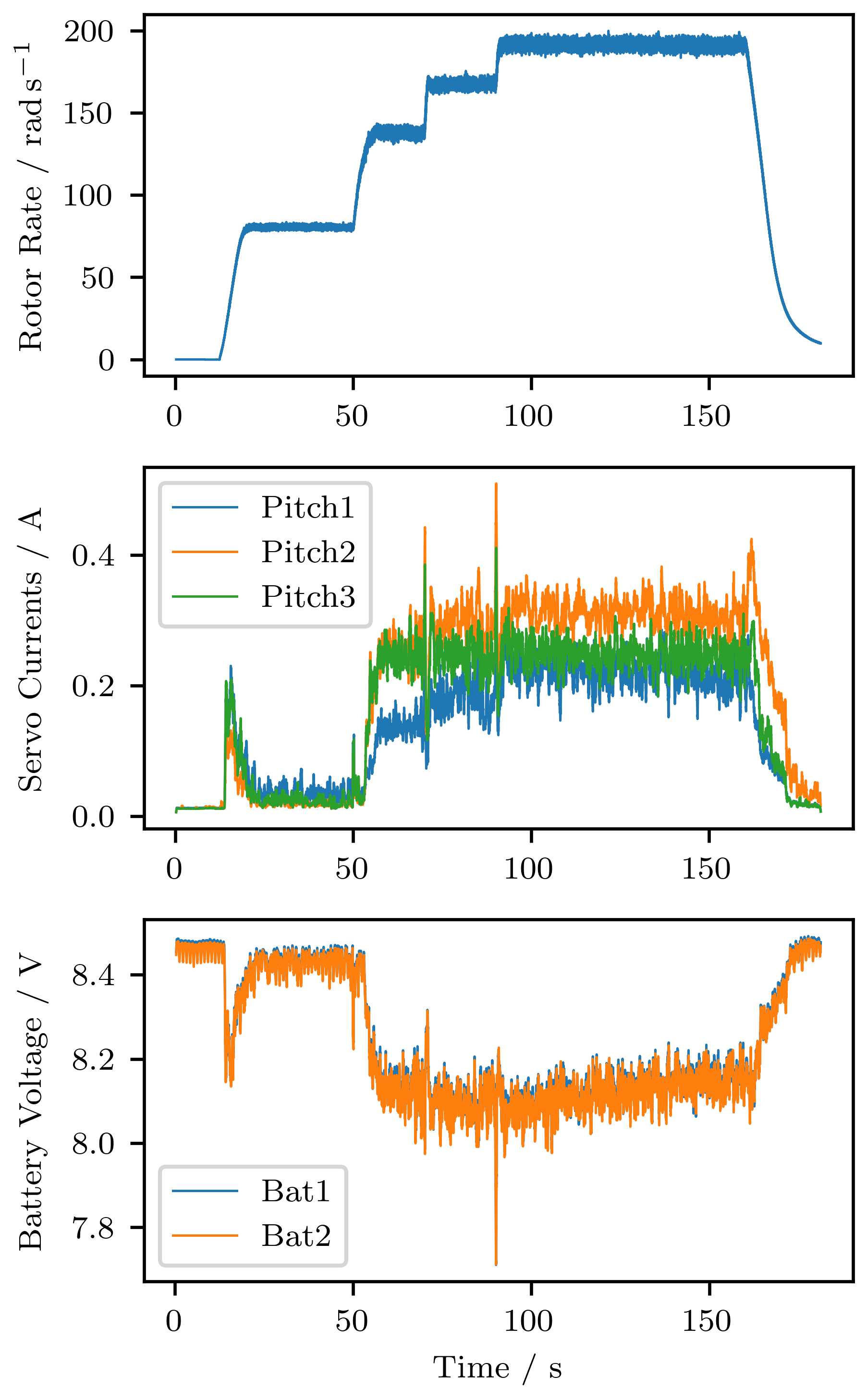
In a standard test environment the tunnel produces constant wind speeds of roughly while the flight controller adjusts the blade pitch of the rotor to reach a target rotor rotation speed. After a pre-programmed time interval a new target speed is chosen to observe the step response of the control algorithm. All sensor readings as well as various internal states would be saved to the flash storage for later detailed analysis with a rate of , just like in a real flight.
One such analysis can be seen in Fig. 9, where the power system was evaluated with special focus on the current draw of the three servos that control the blade pitch. This showed that even under maximum rotor speeds the current was well within design limits, both battery strings were utilized equally, and no critical voltage drops occurred during pitch changes.
5.2 Tachometer Verification
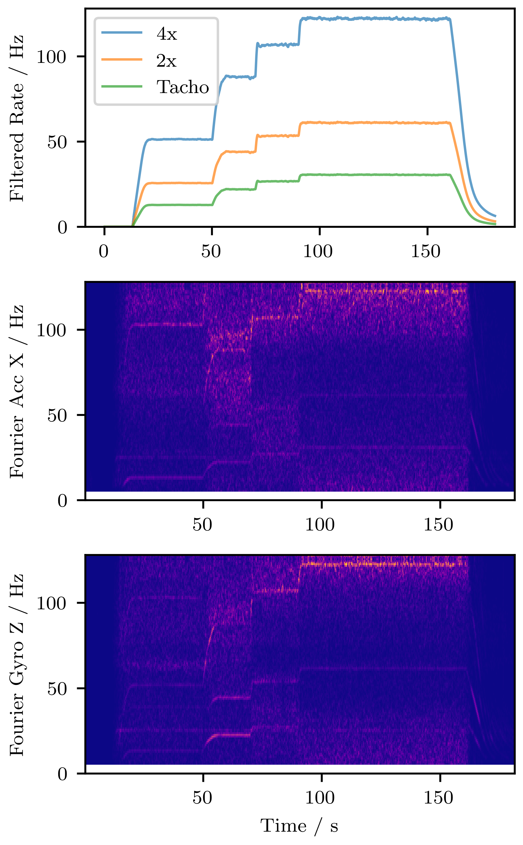
Another critical test involved the verification of the tachometer that measures the rotor rotation rate. This sensor was built from scratch using dedicated logic gates and low-level microcontroller periphery, as well as compensation factors in software. Naturally, the measurements needed to be independently verified before the sensor output could be trusted.
For this the accelerometer and gyroscope readings were used, as the rotor will also induce vibrations corresponding to the rotation rate. These frequencies can be determined by doing a Fourier analysis on the measurements as seen in Fig. 10. Indeed, three distinct waveforms can be seen that correspond exactly to the readings from the tachometer as well as the second and fourth harmonics. The fourth harmonic is the most dominant, which makes sense as the rotor consists of four blades, so most of the vibrations will have a frequency four times higher than the full rotor rotation.
6 Conclusion
This proposed structure, from electronics over communication to system topology, proved valuable and delivered good performance in pre-flight tests such as mechanical shaker tests and flight simulations in a wind-tunnel. Of course, it is impossible to predict all aspects of a real flight, but the system appears robust and will be used as flight hardware in March 2023.
7 Acknowledgements
There are many people and institutions who have supported us in various ways during the project and who deserve to be mentioned here. As far as institutions are concerned, we would like to start with thanking the German Aerospace Center DLR, the Swedish National Aerospace National Space Agency SNSA and the European Space Agency ESA as the main organizers of the REXUS/BEXUS program. In addition, the campaign would not be possible without the Swedish Space Corporation SSC. The Center for Applied Space Technology and Microgravity ZARM also deserves a special Thanks for their continuous support to the team in making improvements and successfully completing the project cycle. Furthermore, we would like to thank the Julius-Maximilians-University Würzburg, in particular the Chair for Aerospace Information Technology [10], represented by Prof. Hakan Kayal. We also express our gratitude to Prof. Sergio Montenegro, who let us use crucial infrastructure like the wind tunnel, an electronics laboratory or his SKITH boards for development during the chip crisis.
The Daedalus 2 team is grateful to all sponsors who made the project possible: Atomstreet, Mouser Electronics, Carbonteam Shop, Hacker Brushless Motors, MathWorks, Siemens, ublox, VDI, Breunig Aerospace, Airbus, Ansys, Hirsch KG, PCB Arts, Vogel Stiftung, MÄDLER, WÜRTH ELEKTRONIK, PartsBox, molex, LRT Automotive, ZfT, Iridium, TELESPAZIO and ARCTIC. An overview of all helpers and sponsors can be found in [6].
References
- [1] Clemens Riegler et al. “PROJECT DAEDALUS, ROTOR CONTROLLED DESCENT AND LANDING ON REXUS23” In 23rd ESA PAC, 2019 URL: https://www.researchgate.net/publication/337819783_PROJECT_DAEDALUS_ROTOR_CONTROLLED_DESCENT_AND_LANDING_ON_REXUS23
- [2] Johanna Mehringer, Lennart Werner, Clemens Riegler and Frederik Dunschen “Suborbital autorotation landing demonstrator on REXUS 29”, 2022 DOI: 10.5821/conference-9788419184405.039
- [3] “High-speed transmission pitch board-to-board connection floating connectors”, 2022 Hirose Electric Co., Ltd. URL: https://www.hirose.com/product/document?clcode=&productname=&series=FX23L&documenttype=Catalog&lang=en&documentid=D141086_en
- [4] “3.0V Primary lithium-sulfur dioxide (\chLi-SO_2)”, 2008 SAFT
- [5] Sergio Montenegro and Frank Dannemann “RODOS - real time kernel design for dependability” In DASIA 2009 - DAta Systems in Aerospace 669, 2009, pp. 66
- [6] “Supporters, Online Presence of WüSpace e. V.” URL: https://www.wuespace.de/supporters/