Photothermal effect in macroscopic optomechanical systems with an intracavity nonlinear optical crystal
Abstract
Intracavity squeezing is a promising technique that may improve the sensitivity of gravitational wave detectors and cool optomechanical oscillators to the ground state. However, the photothermal effect may modify the occurrence of optomechanical coupling due to the presence of a nonlinear optical crystal in an optical cavity. We propose a novel method to predict the influence of the photothermal effect by measuring the susceptibility of the optomechanical oscillator and identifying the net optical spring constant and photothermal absorption rate. Using this method, we succeeded in precisely estimating parameters related to even minor photothermal effects, which could not be measured using a previously developed method.
1 Introduction
The application of cavity optomechanics [1] is a valuable technique used to examine the quantum nature of macroscopic objects. By coupling a mechanical oscillator to an optical cavity using a strong optical field, a wide range of test masses have been evaluated. Sideband cooling [2, 3, 4] is a powerful and well-established technique for cooling a mechanical oscillator to its quantum ground state by using optomechanical coupling [5, 6, 7, 8, 9, 10]. Because the stabilized laser is at thermal equilibrium with the very low-temperature bath, it is possible to significantly decrease the ambient temperature of optomechanical systems by generating a low noise-damping source with light [3].
Optomechanical coupling is also a promising technique for interferometric gravitational wave detectors [11, 12, 13, 14]. While the imaginary component of the optical spring plays a vital role in sideband cooling, the real component of the optical spring improves the sensitivity [15, 16, 17]. When the optical cavity in the interferometer is slightly detuned from resonance, a fraction of the gravitational wave signal field couples to the laser field to generate a radiation pressure force on the test mass. The optical spring then enhances the gravitational wave signal, and the signal-to-noise ratio against quantum noise is improved around the resonant frequency [17, 18].
Although optical springs are used in various applications, a simultaneous increase in the real and imaginary components of the oscillator is not possible because the real and imaginary components of the complex optical spring constant have opposite signs [1, 2, 17]. An optical spring alone is always unstable; therefore, the addition of a mechanical spring or a supplementary control mechanism is essential. Moreover, the most significant problem associated with the effective implementation of optical springs is that the intracavity power limits the impact of the optical spring. It can be challenging to generate an optical spring with firm damping or a strong restoring force without compromising the performance of the interferometer because increasing the cavity finesse narrows the bandwidth of the cavity, while increasing the input power induces thermal lensing or other harmful effects [5, 9, 11, 13].
To solve this problem, the implementation of a technique called intracavity squeezing was originally proposed to generate a stiff optical spring [19, 20]. This technique has been studied as a method for widening the bandwidth of gravitational wave detectors [21, 22, 23] and can reinforce only the signal response of the cavity without increasing the intracavity power. Intracavity squeezing method can also effectively cool down a macroscopic mechanical oscillator to its quantum ground state [24, 25, 26]. It not only enhances the occurrence of optical damping but also induces quantum noise interference for all dissipation ports, eliminating quantum backaction even in the unresolved sideband regime.
Intracavity squeezing method inevitably introduces a photothermal effect in nonlinear optical crystals. Various studies have been conducted on the influence of photothermal effects on laser interferometers. Such photothermal effects acting in the cavity can enable the self-locking of the cavity [27, 28] or conversely induce instabilities [29, 30]. The force exerted by the photothermal effect on the test mass is also referred to as the bolometric force [31, 32, 33, 34], which has been used for optomechanical cooling [3, 35, 36, 37]. Another interesting recent application of the photothermal effect is photothermally induced transparency [38, 39], which is a result of the photothermal effect modifying the effective cavity length. Analogous to the well-known phenomena of electromagnetically induced transparency [40, 41] and optomechanically induced transparency [42, 43, 44], a cavity is realized with an extremely narrow linewidth through the coupling of the optical cavity and an intracavity object. The same research group that developed photothermally induced transparency has also demonstrated that the photothermal effect changes the optical response of the cavity [45].
In this study, we investigate the influence of the photothermal effect in an optomechanical system with a nonlinear optical crystal. The photothermal effect modifies the complex optical spring constant [46, 28, 47] as well as the optical response of the cavity. Specifically, the displacement of the test mass does not match the effective cavity length modified by the photothermal effect, resulting in partial exchange of the real and imaginary components of the optical spring, which may significantly distort the susceptibility of the optomechanical oscillator. The photothermal effect of a nonlinear optical crystal is much more significant than that resulting from cavity optics, which was reported in a previous study [38, 45]; indicating the importance of the problem in the intracavity squeezing systems. To evaluate the effect of intracavity squeezing, it is essential to accurately predict the photothermal effect acting on a nonlinear optical crystal.
The nature of the photothermal effect is determined by the characteristic frequencies of thermal absorption and relaxation in the examined system. These parameters can be obtained via optical response measurements of a cavity [45]. However, when thermal relaxation occurred sufficiently faster than thermal absorption, the photothermal effect quickly reached an equilibrium and the photothermal parameters cannot be easily measured. Therefore, we propose a new method to simultaneously estimate the photothermal absorption rate and optical spring constant by measuring the susceptibility of an optomechanical oscillator over a wide frequency bandwidth. Our method accurately estimates the magnitude of even a minor photothermal effect because a small amount of thermal absorption results in non-negligible optical damping and serves to predict the photothermal effect in various optical systems with an absorptive crystal.
2 Principle
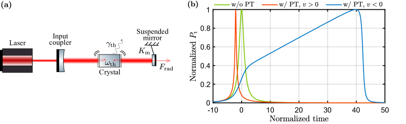
In this section, we discuss the frequency response of an optomechanical system containing a crystal that causes a photothermal effect, as shown in Fig. 1(a). After reviewing the fundamental equations for the photothermal effect, we derive the optical response of the cavity and susceptibility of the optomechanical oscillator with the photothermal effect.
2.1 Fundamental equations of the photothermal effect
Regardless of the existence of an absorptive crystal, the intracavity power can be written as:
| (1) |
where is the cavity finesse and is the carrier power incident on the cavity. We assume that the transmissivity of the input coupler is sufficiently larger than other internal losses and the cavity is sufficiently close to the resonant state. is the normalized cavity detuning, which is proportional to the effective cavity length change where is the actual displacement of the test mass and is the effective change in the cavity optical path length owing to the photothermal effect:
| (2) |
Here, is the angular frequency of the carrier field and is the speed of light. The photothermal displacement is given by , with being the thermal expansion coefficient including the thermo-optic effect (refractive index change with temperature), being the crystal length, being the temperature of the part of the crystal contributing to the photothermal effect (hereafter referred to as the crystal), and being the surrounding temperature. Consequently, over time , is proportional to and thus to the net heat obtained by the crystal:
| (3) |
Here, is the heat capacity of the crystal and and are the time rate of heat flow into and out of the crystal, respectively. The absorption of the carrier light causes the constant thermal inflow into the crystal, which can be written as with the absorption coefficient . The heat outflow can be divided into two parts: one due to the heat conduction or heat transfer and the other due to thermal radiation. However, if the difference between and is small, we can neglect the latter component and the heat outflow can be written as where is the thermal resistance.
2.2 Optical response of the cavity with the photothermal effect
First, we consider the optical response of the cavity. In the optical system shown in Fig. 1(a), the cavity spectrum is not solely Lorentzian because the effective cavity length changes owing to the photothermal effect. Figure 1(b) shows the transmitted power from the cavity when the mirror moves at a constant velocity . If the mirror moves in the same direction as the photothermal displacement to increase thermal absorption, the cavity reaches the resonant point faster than it would in the absence of the photothermal effect, and the linewidth of the spectrum narrows. If the mirror moves in the opposite direction, the photothermal effect cancels the mirror motion until the cavity reaches the resonant point, and the linewidth of the spectrum shows an enormously broadened response [27, 28, 29, 38, 45, 47].
The photothermal effect also modifies the frequency response of the cavity with the reciprocal of the photothermal absorption and relaxation time scale as the characteristic frequency [45], even in a frequency band that is sufficiently lower than the cavity decay rate. We derive the optical response of the cavity from the differential equation formed between the cavity detuning and displacement of the test mass. From Eqs. (1) to (3), the following equation can be derived:
| (4) |
The second term on the right-hand side is nonlinear in but can be linearized by splitting it into the stationary term and the relatively small fluctuating term , i.e., . Only the first-order term of will be considered. We also perform the same operations to and to obtain and , respectively. We then define and . By performing a Fourier transform with the angular frequency , the optical response of the cavity is derived as:
| (5) |
with
| (6) |
which are the photothermal absorption and relaxation rates, respectively. When the thermal absorption occurs faster than the thermal relaxation (), the phase change owing to the photothermal effect is no longer negligible.
A qualitative explanation of the cavity behavior when and is provided as follows. When the mirror moves at a frequency sufficiently higher than , the photothermal effect is not apparent because the signal reverses faster than the occurrence of the photothermal effect. When the mirror moves at a frequency comparable to , the effective cavity length accumulated by the photothermal effect is released as the signal changes, causing a phase lead in the optical response. When the mirror moves sufficiently slowly to cause photothermal relaxation, the phase does not change because the photothermal effect reaches equilibrium, but the gain is reduced because the photothermal effect cancels the effective cavity length change. It should also be noted that the sign of the pole of could be reversed by changing the cavity detuning .
2.3 Susceptibility of the optomechanical oscillator with the photothermal effect
The photothermal effect can contribute to optomechanical coupling in various ways. When mirror distortion due to thermal expansion is used to cool an optomechanical oscillator, the photothermal effect acts directly on the mechanical system as a bolometric force. Because the heating process owing to the photothermal effect defines the cooling limit of such a system, it is necessary to model the photothermal effect using time-delayed forces and then combine it with the semiclassical theory of photon absorption shot noise [32].
In contrast, in the system shown in Fig. 1(a), the photothermal effect affects only the effective cavity length, and no bolometric force acts on the test mass. When the radiation pressure force is proportional to the cavity length change , denoted as wherein the proportionality factor is referred to as the complex optical spring constant, this relationship holds even in the presence of the photothermal effect. However, the displacement of the test mass does not match the effective cavity length change, as shown in Eq. (5), and the complex optical spring constant for the test mass changes as .
The effective susceptibility of the optomechanical oscillator , which is the response from the external force that is applied to the test mass for the displacement of the test mass , can be written as:
| (7) |
where is the effective mass of the suspended mirror and is the complex mechanical spring constant. can be written as using the mechanical spring constant and mechanical damping constant . In addition, when the frequency band under consideration is sufficiently lower than the cavity decay rate (where is the one-way length of the cavity), the complex optical spring constant can be written as using the optical spring constant and optical damping constant , in which the real component is:
| (8) |
A mechanical spring and an optical spring are connected in parallel to the test mass, and the photothermal effect mixes the real and imaginary components of the effective complex optical spring constant. In particular, if the effect of on the complex spring constant is negligible, the photothermal effect converts the real component of the optical spring constant into the imaginary component as:
| (9) |
When and , the real and imaginary components of are positive, which indicates that a single carrier can generate a stable spring [46, 28]. When the frequency band under consideration is sufficiently low (), the magnitude of the imaginary component is maximized when the photothermal absorption and relaxation rates are approximately equal (). However, it should be noted that a slight photothermal effect could cause non-negligible optical damping.
3 Experimental results

3.1 Concept and setup of the experiment
This experiment aimed to evaluate the influence of the photothermal effect on the intracavity squeezing system. The experimental setup is shown in Fig. 2(a). We used a bowtie cavity with a nonlinear optical crystal, which was designed as an optical parametric oscillator cavity; however, one mirror was suspended by a double spiral spring, as shown in Fig. 2(b). There were situations in which measurements needed to be performed without the influence of the optical spring. For these measurements, we replaced the suspended mirror by a piezoelectric element (PZT) and the high-pass filter by a low-pass filter. We used either the signal from the Pound-Drever-Hall technique [48] or the transmitted power as the error signal to control the cavity length, where the former was used for operating points with a slight cavity detuning and the latter for operating points with a large cavity detuning .
This cavity has two mirrors with curvatures of 68.5 mm. The reflectance of the mirrors is % for the input coupler, % for the curved mirror, and more than 99.8% for the small mirror. The designed value of the circular length of the cavity is m. If we neglect intracavity losses caused by crystal and other factors, the cavity decay rate is approximately rad/s, and the finesse is approximately .
Two beam waists are present in the bowtie cavity. The beam radius of the waist between the two flat mirrors is 300 m and that between the two curved mirrors is 40 m. Unless otherwise noted, the nonlinear optical crystal is located at the latter waist. We used either periodically poled LiNbO3 (PPLN) or periodically poled KTiOPO4 (PPKTP) with a length of 10 mm. In this experiment, the nonlinear optical crystal was set to an extreme phase-mismatch condition to evaluate only the photothermal effect. For example, the PPKTP crystal used in this experiment was phase-matched at approximately 35 ∘C, but we heated it to approximately 120 ∘C to collapse the phase-matching condition when measuring the transfer function. Therefore, nonlinear optical effects such as second-harmonic generation can be practically ignored. We measured the finesse in both crystals using weak incident light of approximately mW and obtained .
Because the PPLN crystal has a relatively sizable photothermal absorption rate, it was useful in confirming the occurrence of the photothermal effect. Using this crystal, we report the measurement results of various phenomena caused by the photothermal effect in Sec. 3.2. Owing to the specificities of nonlinear optical crystals and the intracavity squeezing system, we have also succeeded in measuring interesting phenomena that have not yet been reported. Because PPKTP crystals have ideal characteristics for observing an optical spring with the photothermal effect, we report on the susceptibility measurement results obtained using this crystal in Sec. 3.3. In addition to confirming that the photothermal effect causes significant optical damping, we also successfully performed high-accuracy parameter estimation related to the optical spring and photothermal effect.
3.2 Measurement of the photothermal effect

If the photothermal absorption rate is sufficiently greater than the photothermal relaxation rate , the photothermal effect can be easily confirmed in several ways. Here, we measured the simple and various photothermal effects by replacing the suspension with a PZT. We used a PPLN crystal to induce the photothermal effect with a high incident power of 600 mW (measurement error: %).
Figures 3(a) and 3(b) show the transmitted power measured using the cavity scan. Figure 3(a) shows the spectrum obtained as the mirror moves in the direction of increasing cavity length, which appears to be narrower at the half-maximum width than in the case without the photothermal effect. Figure 3(b) shows the spectrum with the mirror moving in the opposite direction, in which case it takes an extremely long time to reach the resonant state. These trends are in agreement with the simulation results shown in Fig. 1(b), where the effective cavity length increases as the intracavity power increases, indicating that the coefficient of the photothermal effect is positive.
As shown in Sec. 2.2, the modification of the effective cavity length by the photothermal effect causes the cavity to exhibit a frequency response. Using an actuator with a resonant frequency that is sufficiently higher than that of the optical spring, such as a PZT, we can directly measure the optical response of the cavity . Figure 3(c) shows the optical response of the cavity. Because the gain of varies with the PD and electrical driver, only the phase measurement results are shown here. At the initial phase of this measurement, the thermal lens effect of the PPLN caused a severe mode mismatch, so we repositioned the PPLN crystal to pass a 300-m beam waist. The crystal clipped the beam and the finesse was reduced to approximately . Even under these conditions, we observed a noticeable change in the optical response of the cavity because we achieved the condition . As shown in Eq. (5), is the phase-lead compensation when and . However, when and , the phase becomes approximately degrees in the bandwidth below .
The measured results are inconsistent with the theory in the band below approximately 15 Hz. When the signal was varied slowly, the effective heat capacity may have increased because the region that contributes to the heat outflow became wider. Therefore, the effective exhibits a frequency response that decreases in the low-frequency band. The measured data becomes consistent with the theory if we use only data above 15 Hz for fitting. The estimated parameters are Hz and Hz for , and Hz and Hz for . In the case of , the fitting accuracy may have been low because does not significantly change even if the parameters are changed significantly.
When the cavity length changes owing to the photothermal effect, we can self-lock the cavity without the use of any feedback control mechanism. In particular, because our experimental system was equipped with a crystal heater for phase matching, we were able to control the cavity near the resonance point without the use of an actuator. Figure 3(d) shows the transmitted power and temperature during the self-locking process. We installed the PPLN crystal to pass a 300-m beam waist once again for this experiment. The crystal was kept at room temperature and the cavity was out of resonance at s. We switched on the heater at s, and the effective cavity length increased by several m because of thermal expansion as the crystal temperature increased. After s, heat slowly flowed out of the entire crystal and the effective cavity length decreased. However, after s, the intracavity power became more robust, and the heat inflow due to carrier light absorption began. When these two factors were balanced, the crystal temperature and intracavity power stabilized and the self-locking of the cavity was achieved.
3.3 Measurement of the optomechanical response function with the photothermal effect

From Eq. (9), the imaginary component of the optical spring constant reaches its maximum value when , and when is increased further, the decrease in the real component of the optical spring constant cannot be ignored. The magnitude of depends on the input power and normalized cavity detuning , but when mW and , of the PPLN crystal is approximately four times larger than , and the complex optical spring constant is not adequately large for both the real and imaginary components. However, because the PPKTP crystal achieved approximately under these parameters and the thermal lens effect was negligible, we measured the optical spring constants using this crystal.
Initially, the characteristics of the mechanical suspensions were examined. The angular frequency of the mechanical resonance was roughly estimated to be Hz through the measurement of the oscillation magnitude with the signal applied to the coil. The mechanical Q factor was estimated to be through the ringdown measurement using the shadow sensing method. The contribution of the optical spring to the damping loss angle can be calculated as , where is the resonant angular frequency of the optical spring. Without the photothermal effect, the mechanical damping was dominant and the optical damping was negligible.
Because is constant regardless of the input power and cavity detuning, we estimated it from measurements using a PZT. We measured for various and values but could not estimate the parameters when the condition was not satisfied. We performed multiple measurements with parameters for which was sufficiently large, and by taking their weighted average, we estimated Hz.
Based on the estimated results for these parameters, we investigated the influence of the photothermal effect on the optical spring. The setup shown in Fig. 2(a) was used to measure the combined spring constant owing to the optical spring and mechanical suspension system. The optomechanical response function is , from the force applied to the test mass for the effective cavity length change . We set to three patterns of 600, 300, and 150 mW, and varied finely in the range of approximately . When 600 mW was injected, and the cavity was in the resonance state and the most intense second harmonic was generated. Even then, the intracavity loss estimated from the reflected power measurement was approximately 0.074 times the input coupler loss, and therefore the condition of overcoupling was satisfied.
Figure 4(a) shows a representative sample of the phase measurement results of the optomechanical response function. We performed the fitting using the optical spring constants and as the parameters. As we have shown in Eqs. (6) and (8), and exhibit the same functional dependence on and . These parameters are maximized when . Here, we show the measured data for approximately . Larger values correspond to smaller and values.
The effect of on the optomechanical response function appears at the resonance frequency, which is the frequency at which the phase is approximately degrees. It can be seen that a larger and smaller result in a higher resonant frequency. The effect of appears mainly in the optical damping and phase-lead phenomena. Optical damping is caused by converting the real component of the complex optical spring constant into an imaginary component through the photothermal effect. Even if optical damping in the absence of the photothermal effect is negligible, this conversion process can significantly change the damping constant of the entire optomechanical system. The measurement results show that the phase inversion of the optomechanical response function was more gradual than it would in the absence of the photothermal effect. In addition, a change in the optical response of the cavity due to the photothermal effect caused a phase lead. The measured phase is led by more than degrees in a band higher than the resonant frequency.
If and are chosen to have an identical for a certain parameter set, the photothermal absorption rate , and thus the response function as well, become identical. For example, although and were different for the bright red ( mW, ) and dark green ( mW, ) curves in Fig. 4(a), the response functions almost perfectly overlapped, reflecting the fact that and were estimated to be nearly identical.
The estimation results for and are shown in Figs. 4(b) and 4(c). The circles with error bars represent the estimated values of and obtained using the same fitting method as in Fig. 4(a). In these measurements, we varied such that the ranges of the transmitted power variations were approximately equal. However, we excluded the measurement results where the parameters were not identifiable in the fitting program, and the variance was estimated to be zero. The solid lines show the fitting results with the inverse of the variance of the estimates as weights. We estimated the maximum values of and for each input power. The estimated maximum for mW corresponds to Hz in terms of the resonant frequency of the optical spring.

Figure 5 shows the maximum values of and estimated from the fitting results. The circles with error bars represent estimates of the respective maximum values, with blue corresponding to and red corresponding to . The dotted lines show the results of further fitting these estimates with the inverse of their variances as weights, and both are shown to be approximately linear functions with an intercept of zero.
4 Discussion
We compare our measurement results with those of a previous experiment using fused silica [45]. Although the intracavity power in our experiment was less than of the previous experiment, we observed a comparable photothermal absorption rate because of the more significant thermal absorption coefficient and thermal expansion coefficient of the nonlinear optical crystal. Because there was no significant difference in the specific heat and thermal conductivity of the crystals used in the two experiments, the photothermal relaxation rates were also comparable. An experiment using PPLN caused serious mode mismatch due to the thermal lens effect, which may be related to the significant thermo-optic coefficient of PPLN compared to other crystals [49, 50].
We estimated by measuring the optical response of the cavity using a fixed mirror with a PZT. If the beam radius is constant in the part that contributes to thermal absorption, can be determined using the physical property values of the crystal [51],
| (10) |
where denotes the thermal conductivity, denotes the density, and denotes the specific heat capacity. For the experiment using PPKTP, the beam radius of the waist is 40 m, the crystal length is 10 mm, the refractive index is 1.7, the thermal conductivity of KTP is [52], , and , from which the average value of is approximately 95 Hz. This value is approximately 3.2 times higher than that measured in Sec. 3.3. This difference may be because of the extra thermal resistance at the junction of the periodic polarization inversion. It should also be noted that the beam radius is sensitive to the position of the curved mirror and crystal; therefore, the estimate of the beam radius used in the calculation may be inaccurate. If the beam radius is accurately measured, this method is sufficiently accurate to be applied to the high-precision estimation of thermal conductivity [45].
We estimated in two ways: by measuring the optical response of the cavity and by measuring the optomechanical response function . Although can be measured with a simple experimental system using a fixed mirror, is required for accurate parameter estimation. Conversely, the measurement of using a suspended mirror is a promising parameter estimation method, even when is small, because a minor photothermal effect can induce non-negligible optical damping.
To compare the two parameter estimation methods, we calculated the root mean square error (RMSE) for estimating the maximum value of . The estimation results obtained using the suspended mirror are presented in Fig. 4(c). The RMSEs normalized by the estimated maximum of were 0.0074 for mW of input power, 0.011 for mW, and 0.035 for mW, showing an excellent agreement between the fitting and measurement results. Conversely, when we estimated only using a fixed mirror for similar parameters, the normalized RMSEs were 0.052 for 600 mW, 0.16 for 300 mW, and 0.41 for 150 mW. These are approximately ten times worse than the estimation results obtained using a suspended mirror, which implies that systematic errors in the estimation method using a fixed mirror were not non-negligible when . We note that there is also a lower limit for that can be estimated from measurements using a suspended mirror, which is determined by the minimum optical damping that can be measured.
There are several other methods for estimating photothermal parameters. One is to measure the temperature decay owing to heat dissipation. can also be estimated from the time required to achieve photothermal self-locking, as introduced in Sec. 3.2. However, our investigations shows that neither of these methods worked. We heated the crystal to 50 ∘C and measured the time required for the crystal to be cooled down to 20 ∘C, but the estimated parameters were orders of magnitude smaller than the value obtained in the measurement, probably because of the additional heat capacities of the heater and thermometer. Another option is to estimate the parameters from the spectrum of the cavity scan relying on the qualitative agreement with the simulation results, but this was not achievable because of the poor linearity of the PZT actuator.
In these experiments, it was essential to maintain the nonlinear optical crystal in the extreme phase-mismatch condition to avoid nonlinear optical effects. However, a fraction of secondary harmonics was generated and could have affected the measurement in the case with a high input power. In Figs. 4(b) and 4(c), when the incident light power was mW and the normalized cavity detuning was close to , the measurement results somewhat deviated from the fitting function, possibly because of the nonlinear optical effects. Although we have successfully estimated the parameters with reasonable accuracy, the effect of optical loss, which depends on the intracavity power, should be considered when using optical systems that are more susceptible to nonlinear optical effects.
The change in the frequency response owing to the photothermal effect is a phenomenon that occurs only in the low-frequency band, and if the measurement frequency band is sufficiently higher than , the photothermal effect may be negligible. However, because the optical spring constant and photothermal absorption rate exhibit the same functional dependence on the input power, cavity detuning, and finesse, the photothermal effect cannot be avoided by generating a stiff optical spring and increasing the measurement bandwidth. Therefore, unless the physical property values of a nonlinear optical crystal are improved, the photothermal effect must be considered when dealing with intracavity squeezing systems composed of macroscopic and massive test masses. Parameter estimation using the method presented in this paper and predicting the photothermal effect will allow us to correctly discuss the intracavity squeezing effect.
Combining intracavity squeezing and the photothermal effect can be a strong tool for manipulating an optical spring. Even when the intracavity power is low, a stiff optical spring can be generated by implementing an intracavity squeezing method [19, 20]. Moreover, even when only a single carrier is used, the real and imaginary components of the complex optical spring constant can be positive in the frequency band where the photothermal effect is dominant [46, 28]. Optical springs have two inherent problems as they are unstable on their own and the intracavity power limits the magnitude of the spring constant. However, combining the photothermal effect and intracavity squeezing can solve these two problems simultaneously. It is also worth noting that the optical spring generated in such a system has high design flexibility. Although the method described in Sec. 2 is helpful for more advanced theoretical calculations, such as when implementing an intracavity squeezing technique, a derivation using Hamiltonian notation is provided in Supplement 1 for a more detailed discussion. We conclude that intracavity squeezing can enhance the optical spring constant and photothermal absorption rate by the same factor.
5 Conclusion
In this study, we investigated the influence of the photothermal effect on intracavity squeezing systems. As a result, we found that the photothermal effect profoundly influences the optical response of the cavity and susceptibility of the optomechanical oscillator. When dealing with intracavity squeezing systems composed of macroscopic test masses, the influence of photothermal effects must necessarily be considered. Experimentally, the measured susceptibility of the optomechanical oscillator with the photothermal effect agreed with the theoretical model. The resonant frequency of the optical spring in the absence of the photothermal effect was accurately estimated with a standard error of less than 1%. We also demonstrated that even a minor photothermal effect can be estimated more accurately than via the previously developed method by measuring the optomechanical response function. While the intracavity squeezing method is known to help increasing the optical spring constant, the photothermal effect can play a complimentary role to stabilize the optical spring. An appropriate combination of the two techniques allows us to design a sensitive and stable optomechanical probe for the precise measurement.
Funding Core Research for Evolutional Science and Technology (JPMJCR1873); Japan Society for the Promotion of Science (20J22778); Sumitomo Foundation (200629). \bmsectionAcknowledgments We would like to thank Jerome Degallaix and colleagues at the LMA for providing us a specially coated mirror, and we would like to thank John Winterflood from UWA for designing the double spiral spring. \bmsectionDisclosures The authors declare no conflicts of interests. \bmsectionData availability Data underlying the results presented in this paper are not publicly available at this time but may be obtained from the authors upon reasonable request. \bmsectionSupplemental document See Supplement 1 for the supporting content.
References
- [1] M. Aspelmeyer, T. J. Kippenberg, and F. Marquardt, “Cavity optomechanics,” \JournalTitleRev. Mod. Phys. 86, 1391–1452 (2014).
- [2] O. Arcizet, P.-F. Cohadon, T. Briant, M. Pinard, and A. Heidmann, “Radiation-pressure cooling and optomechanical instability of a micromirror,” \JournalTitleNature 444, 71–74 (2006).
- [3] S. Gigan, H. R. Böhm, M. Paternostro, F. Blaser, G. Langer, J. B. Hertzberg, K. C. Schwab, D. Bäuerle, M. Aspelmeyer, and A. Zeilinger, “Self-cooling of a micromirror by radiation pressure,” \JournalTitleNature 444, 67–70 (2006).
- [4] A. Schliesser, P. Del’Haye, N. Nooshi, K. J. Vahala, and T. J. Kippenberg, “Radiation pressure cooling of a micromechanical oscillator using dynamical backaction,” \JournalTitlePhys. Rev. Lett. 97, 243905 (2006).
- [5] J. D. Teufel, T. Donner, D. Li, J. W. Harlow, M. S. Allman, K. Cicak, A. J. Sirois, J. D. Whittaker, K. W. Lehnert, and R. W. Simmonds, “Sideband cooling of micromechanical motion to the quantum ground state,” \JournalTitleNature 475, 359–363 (2011).
- [6] J. Chan, T. P. M. Alegre, A. H. Safavi-Naeini, J. T. Hill, A. Krause, S. Gröblacher, M. Aspelmeyer, and O. Painter, “Laser cooling of a nanomechanical oscillator into its quantum ground state,” \JournalTitleNature 478, 89–92 (2011).
- [7] E. Verhagen, S. Deléglise, S. Weis, A. Schliesser, and T. J. Kippenberg, “Quantum-coherent coupling of a mechanical oscillator to an optical cavity mode,” \JournalTitleNature 482, 63–67 (2012).
- [8] M. Underwood, D. Mason, D. Lee, H. Xu, L. Jiang, A. B. Shkarin, K. Børkje, S. M. Girvin, and J. G. E. Harris, “Measurement of the motional sidebands of a nanogram-scale oscillator in the quantum regime,” \JournalTitlePhys. Rev. A 92, 061801 (2015).
- [9] R. W. Peterson, T. P. Purdy, N. S. Kampel, R. W. Andrews, P.-L. Yu, K. W. Lehnert, and C. A. Regal, “Laser cooling of a micromechanical membrane to the quantum backaction limit,” \JournalTitlePhys. Rev. Lett. 116, 063601 (2016).
- [10] L. Qiu, I. Shomroni, P. Seidler, and T. J. Kippenberg, “Laser cooling of a nanomechanical oscillator to its zero-point energy,” \JournalTitlePhys. Rev. Lett. 124, 173601 (2020).
- [11] G.M. Harry, LIGO Scientific Collaboration, “Advanced LIGO: the next generation of gravitational wave detectors,” \JournalTitleClass. Quantum Grav. 27, 084006 (2010).
- [12] F. Acernese, M. Agathos, K. Agatsuma, et al., “Advanced virgo: a second-generation interferometric gravitational wave detector,” \JournalTitleClass. Quantum Grav. 32, 024001 (2014).
- [13] B. Willke, P. Ajith,B. Allen, et al., “The GEO-HF project,” \JournalTitleClass. Quantum Grav. 23, S207–S214 (2006).
- [14] K. Somiya, “Detector configuration of KAGRA–the japanese cryogenic gravitational-wave detector,” \JournalTitleClass. Quantum Grav. 29, 124007 (2012).
- [15] A. Buonanno and Y. Chen, “Optical noise correlations and beating the standard quantum limit in advanced gravitational-wave detectors,” \JournalTitleClass. Quantum Grav. 18, L95–L101 (2001).
- [16] A. Buonanno and Y. Chen, “Quantum noise in second generation, signal-recycled laser interferometric gravitational-wave detectors,” \JournalTitlePhys. Rev. D 64, 042006 (2001).
- [17] A. Buonanno and Y. Chen, “Signal recycled laser-interferometer gravitational-wave detectors as optical springs,” \JournalTitlePhys. Rev. D 65, 042001 (2002).
- [18] Y. Chen, “Macroscopic quantum mechanics: theory and experimental concepts of optomechanics,” \JournalTitleJ. Phys. B: At. Mol. Opt. Phys. 46, 104001 (2013).
- [19] K. Somiya, Y. Kataoka, J. Kato, N. Saito, and K. Yano, “Parametric signal amplification to create a stiff optical bar,” \JournalTitlePhys. Lett. A 380, 521–524 (2016).
- [20] M. Korobko, F. Khalili, and R. Schnabel, “Engineering the optical spring via intra-cavity optical-parametric amplification,” \JournalTitlePhys. Lett. A 382, 2238–2244 (2018). Special Issue in memory of Professor V.B. Braginsky.
- [21] H. Rehbein, J. Harms, R. Schnabel, and K. Danzmann, “Optical transfer functions of kerr nonlinear cavities and interferometers,” \JournalTitlePhys. Rev. Lett. 95, 193001 (2005).
- [22] M. Korobko, L. Kleybolte, S. Ast, H. Miao, Y. Chen, and R. Schnabel, “Beating the standard sensitivity-bandwidth limit of cavity-enhanced interferometers with internal squeezed-light generation,” \JournalTitlePhys. Rev. Lett. 118, 143601 (2017).
- [23] M. Korobko, Y. Ma, Y. Chen, and R. Schnabel, “Quantum expander for gravitational-wave observatories,” \JournalTitleLight: Science & Applications 8, 118 (2019).
- [24] S. Huang and G. S. Agarwal, “Enhancement of cavity cooling of a micromechanical mirror using parametric interactions,” \JournalTitlePhys. Rev. A 79, 013821 (2009).
- [25] M. Asjad, N. E. Abari, S. Zippilli, and D. Vitali, “Optomechanical cooling with intracavity squeezed light,” \JournalTitleOpt. Express 27, 32427–32444 (2019).
- [26] J.-H. Gan, Y.-C. Liu, C. Lu, X. Wang, M. K. Tey, and L. You, “Intracavity-squeezed optomechanical cooling,” \JournalTitleLaser Photonics Rev. 13, 1900120 (2019).
- [27] T. Carmon, L. Yang, and K. J. Vahala, “Dynamical thermal behavior and thermal self-stability of microcavities,” \JournalTitleOpt. Express 12, 4742–4750 (2004).
- [28] P. A. Altin, T. T.-H. Nguyen, B. J. J. Slagmolen, R. L. Ward, D. A. Shaddock, and D. E. McClelland, “A robust single-beam optical trap for a gram-scale mechanical oscillator,” \JournalTitleSci. Rep. 7, 14546 (2017).
- [29] K. Konthasinghe, J. G. Velez, A. J. Hopkins, M. Peiris, L. T. M. Profeta, Y. Nieves, and A. Muller, “Self-sustained photothermal oscillations in high-finesse fabry-perot microcavities,” \JournalTitlePhys. Rev. A 95, 013826 (2017).
- [30] J. Ma, J. Qin, G. T. Campbell, G. Guccione, R. Lecamwasam, B. C. Buchler, and P. K. Lam, “Observation of nonlinear dynamics in an optical levitation system,” \JournalTitleCommun. Phys. 3, 197 (2020).
- [31] M. Pinard and A. Dantan, “Quantum limits of photothermal and radiation pressure cooling of a movable mirror,” \JournalTitleNew J. Phys. 10, 095012 (2008).
- [32] S. De Liberato, N. Lambert, and F. Nori, “Quantum noise in photothermal cooling,” \JournalTitlePhys. Rev. A 83, 033809 (2011).
- [33] J. Restrepo, J. Gabelli, C. Ciuti, and I. Favero, “Classical and quantum theory of photothermal cavity cooling of a mechanical oscillator,” \JournalTitleC. R. Phys. 12, 860–870 (2011). Nano- and micro-optomechanical systems.
- [34] M. Abdi, A. R. Bahrampour, and D. Vitali, “Quantum optomechanics of a multimode system coupled via a photothermal and a radiation pressure force,” \JournalTitlePhys. Rev. A 86, 043803 (2012).
- [35] C. H. Metzger and K. Karrai, “Cavity cooling of a microlever,” \JournalTitleNature 432, 1002–1005 (2004).
- [36] C. Metzger, I. Favero, A. Ortlieb, and K. Karrai, “Optical self cooling of a deformable fabry-perot cavity in the classical limit,” \JournalTitlePhys. Rev. B 78, 035309 (2008).
- [37] G. Jourdan, F. Comin, and J. Chevrier, “Mechanical mode dependence of bolometric backaction in an atomic force microscopy microlever,” \JournalTitlePhys. Rev. Lett. 101, 133904 (2008).
- [38] J. Ma, J. Qin, G. T. Campbell, R. Lecamwasam, K. Sripathy, J. Hope, B. C. Buchler, and P. K. Lam, “Photothermally induced transparency,” \JournalTitleSci. Adv. 6, eaax8256 (2020).
- [39] M. Clementi, S. Iadanza, S. A. Schulz, G. Urbinati, D. Gerace, L. O’Faloain, and M. Galli, “Thermo-optically induced transparency on a photonic chip,” \JournalTitleLight Sci. Appl. 10, 240 (2021).
- [40] K.-J. Boller, A. Imamoğlu, and S. E. Harris, “Observation of electromagnetically induced transparency,” \JournalTitlePhys. Rev. Lett. 66, 2593–2596 (1991).
- [41] M. Fleischhauer, A. Imamoglu, and J. P. Marangos, “Electromagnetically induced transparency: Optics in coherent media,” \JournalTitleRev. Mod. Phys. 77, 633–673 (2005).
- [42] G. S. Agarwal and S. Huang, “Electromagnetically induced transparency in mechanical effects of light,” \JournalTitlePhys. Rev. A 81, 041803 (2010).
- [43] S. Weis, R. Rivière, S. Deléglise, E. Gavartin, O. Arcizet, A. Schliesser, and T. J. Kippenberg, “Optomechanically induced transparency,” \JournalTitleScience 330, 1520–1523 (2010).
- [44] A. H. Safavi-Naeini, T. P. M. Alegre, J. Chan, M. Eichenfield, M. Winger, Q. Lin, J. T. Hill, D. E. Chang, and O. Painter, “Electromagnetically induced transparency and slow light with optomechanics,” \JournalTitleNature 472, 69–73 (2011).
- [45] J. Ma, G. Guccione, R. Lecamwasam, J. Qin, G. T. Campbell, B. C. Buchler, and P. K. Lam, “Optical back-action on the photothermal relaxation rate,” \JournalTitleOptica 8, 177–183 (2021).
- [46] D. Kelley, J. Lough, F. Mangaña Sandoval, A. Perreca, and S. W. Ballmer, “Observation of photothermal feedback in a stable dual-carrier optical spring,” \JournalTitlePhys. Rev. D 92, 062003 (2015).
- [47] J. Qin, G. Guccione, J. Ma, C. Gu, R. Lecamwasam, B. C. Buchler, and P. K. Lam, “Cancellation of photothermally induced instability in an optical resonator,” \JournalTitleOptica 9, 924–932 (2022).
- [48] R. W. P. Drever, J. L. Hall, F. V. Kowalski, J. Hough, G. M. Ford, A. J. Munley, and H. Ward, “Laser phase and frequency stabilization using an optical resonator,” \JournalTitleAppl. Phys. B 31, 97–105 (1983).
- [49] G. Ghosh, “Thermo-optic coefficients of linbo3, liio3, and litao3 nonlinear crystals,” \JournalTitleOpt. Lett. 19, 1391–1393 (1994).
- [50] J. Mangin, G. Gadret, and G. Mennerat, “Dispersion and temperature dependence of thermo-optic coefficients of optical materials over their whole transparency range: vectorial formalism and application to KTiOPO4,” in Optical Fabrication, Testing, and Metrology III, vol. 7102 A. Duparré and R. Geyl, eds., International Society for Optics and Photonics (SPIE, 2008), pp. 354 – 362.
- [51] M. Cerdonio, L. Conti, A. Heidmann, and M. Pinard, “Thermoelastic effects at low temperatures and quantum limits in displacement measurements,” \JournalTitlePhys. Rev. D 63, 082003 (2001).
- [52] C. A. Ebbers and S. P. Velsko, “Optical and thermo-optical characterization of KTP and its isomorphs for 1.06-um-pumped OPOs,” in Nonlinear Frequency Generation and Conversion, vol. 2700 M. C. Gupta, W. J. Kozlovsky, and D. C. MacPherson, eds., International Society for Optics and Photonics (SPIE, 1996), pp. 227 – 239.