Nematronics: Reciprocal coupling between ionic currents and nematic dynamics
Abstract
Adopting a spintronics-inspired approach, we study the reciprocal coupling between ionic charge currents and nematic texture dynamics in a uniaxial nematic electrolyte. Assuming quenched fluid dynamics, we develop equations of motion analogously to spin torque and spin pumping. Based on the principle of least dissipation of energy, we derive the adiabatic “nematic torque” exerted by ionic currents on the nematic director field as well as the reciprocal motive force on ions due to the orientational dynamics of the director. We discuss several simple examples that illustrate the potential functionality of this coupling. Furthermore, using our phenomenological framework, we propose a practical means to extract the coupling strength through impedance measurements on a nematic cell. Exploring further applications based on this physics could foster the development of nematronics – nematic iontronics.
Introduction.—The reciprocal coupling between magnetic and electric degrees of freedom is the hallmark of spintronics [1, 2]. There are myriad proposals to exploit electron mediated spin torque and spin pumping for novel devices and applications [3], such as creating energy storage devices [4, 5], spin-based memory [6, 7, 8, 9], and methods for long-range signal transport [1, 10, 11]. For soft condensed matter and biological systems, we extend the spintronics approach of studying effective torques and motive forces to nematic electrolytes (i.e. ion-doped nematic liquid crystal). Here, the nematic director plays the role of spin and ions take the place of electrons as the main charge carriers. Nematic electrolytes are natural systems to apply a spintronics-based approach because they share similar order parameter spaces and homotopic properties with magnetic systems [12, 13, 14, 15, 16].
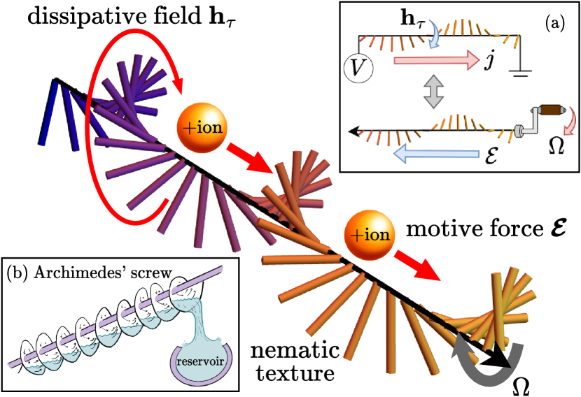
Drawing inspiration from spintronics, we will study a reciprocal coupling between ionic and nematic degrees of freedom, using it to drive nematic texture and pump charge current. This coupling is visualized in Fig. 1 as the analog of Archimedes’ screw, a hydraulic machine that can be used to either pump water or generate energy as a turbine [17]. Similarly, nematic dynamics driven by external means [18] pump ionic currents and, reciprocally, an ionic current (realized via an external electric field) exerts a torque on the nematic texture, generating work. Previous works on nemato-ionic interactions have focused on liquid-crystal enabled electrokinetics, in which applied electric fields are used to induce osmotic flows or to transport suspended particles within liquid crystals [19, 20, 21, 22] From a symmetry perspective, our proposed coupling is similar to the Lehmann effect, which describes the rotation of chiral nematics due to a temperature gradient [23, 24], electric fields [25], or concentration gradients [26, 27]. Moreover, via the inverse Lehmann effect, a chiral nematic can pump particle flux [28]. For the Lehmann effect, the chirality of the system breaks inversion symmetry. This consequently leads to an effective field (and motive force satisfying Onsager reciprocity) stemming from the chiral coupling term [28]. In contrast, here we instead utilize couplings to spatial gradients of the nematic texture to reduce the symmetries of the director field configuration and study the subsequent dynamics. Such gradient field configurations can be induced by boundary conditions or topological defects.
In this Letter, we develop equations of motion analogously to spin torque and spin pumping for nematic electrolytes. To this end, we first specify the free energy and Rayleighan, then derive the dynamic equations from the principle of least dissipation. We discuss how, via this coupling, nematic dynamics give rise to inductance and how ionic current can be used to transport topological defects. By doing so, we aim at laying out building blocks for nematronics.
Dynamic equations.—In the minimal model, consider a closed container filled with an incompressible dilute uniaxial nematic electrolyte. The orientational structure is described by the nematic director field , with unit norm. The fluid dynamics can be quenched when the fluid stiffness and finite system size results in faster fluid motion than director and ionic dynamics [29]. The electrolyte consists of two freely moving monovalent ion species, with cationic density and anionic density . Formally, this system can be decomposed into a charge sector, characterized by and a neutral “osmotic” sector, characterized by . Here, is the electric charge. Suppose we drive the system electrically so that the time scales of the two sectors separate. This results in faster plasmonic charge dynamics on top of the slower diffusive osmotic dynamics. Focusing on the faster charge sector, the remaining degrees of freedom are and [30]. Furthermore, the response in the charge sector may be approximated by the dynamics of the more mobile of the two ion species.
The equations of motion governing the nemato-ionic response are
| (1a) | ||||
| (1b) | ||||
| which are written in terms of Onsager-reciprocal constitutive relations | ||||
| (1c) | ||||
| (1d) | ||||
Once the free energy is specified, in Eq. (1a) is the effective field thermodynamically conjugate to the director field , with components parallel to projected out to fix . is a phenomenological parameter characterizing the “rotational viscosity” [31] and . is the effective diffusivity tensor in the charge sector, which accounts for the anisotropy of the nematic texture. It is constructed on symmetry grounds as . is the homogenous bulk ion density. is the effective electrochemical potential conjugate to the charge density . Finally, is a phenomenological coefficient parameterizing the rotation imparted upon the nematic texture due to .
The ion-induced field in Eq. (1a) is fully analogous to the adiabatic “spin-transfer torque” in spin systems [32, 33], and describes the torque exerted by the electric charge current onto the nematic texture. Reciprocally, director dynamics induces a motive force , given by Eq. (1d), which pumps a diffusive charge current , given by Eq. (1b). and are only nonzero for systems out of equilibrium, i.e. displaced from the minimum free energy. We note that and are independently symmetric under rotations in real and order parameter space. This symmetry is artificial because, in general, it is broken by additional terms. Moreover, only the combined symmetry corresponding to simultaneous rotations of real space and director orientation survives in a fluid. The Supplemental Material provides a more complete discussion of these “artificial” symmetries [29].
Framework.—With the free energy and Rayleighan , we employ the principle of least dissipation of energy, , to derive the dynamic equations. In this expression, are the generalized velocities and . We have assumed that the system has a uniform nematic order parameter. However, it is straightforward to generalize by constructing and with the tensorial nematic order parameter instead of [34, 20]. Furthermore, the material flow of the nematic fluid is not an explicit degree of freedom. This can be a limiting assumption in electrohydrodynamic systems [21, 20, 22] but qualitatively accepted, for example, in confined geometries [35, 36].
Our model incorporates ionic degrees of freedom into the Ericksen-Leslie formalism of nematodynamics [37]. Similar models have been derived which focused on electrohydrodynamic effects but did not include the reciprocal nemato-ionic coupling [21, 20, 38]. In our model, the total free energy is
| (2) | ||||
is the elastic constant, is the electric potential, and is the dielectric tensor constructed analogously to the diffusivity tensor.
The first term is the free energy density of the nematic texture which accounts for the elasticity of the liquid crystal. We assume the “equal constant approximation,” where splay, twist, and bend modes have equal elastic constant [39]. This corresponds to the aforementioned “artificial” symmetries in which the system is separately isotropic in real and order parameter space. The second term, , describes the nonelectrostatic ionic part of the free energy density. The final two terms are the electrostatic contributions to the free energy. They give the Poisson equation in an anisotropic dielectric upon ,
| (3) |
Note that the flexoelectric free energy could be included, but our focus is on the kinematic effects corresponding to the nemato-ionic response [29, 40, 41].
The Rayleigh functions capturing linear dissipative forces are positive definite and quadratic in generalized velocities. They are given by
| (4a) | ||||
| (4b) | ||||
| (4c) | ||||
Here, governs the relaxation of the director field to its equilibrium configuration. describes the friction of electric charge currents, where the effective diffusivity tensor is . Eqs (4a) and (4b) can be found in Refs. [21, 20, 22]. is the friction term coupling electric charge current to director dynamics. It respects the previously discussed “artificial” symmetries and is constructed to leading order in spatial derivatives of . being positive-definite constrains , , and [42, 43].
Having specified and , we now apply the principle of least dissipation. Taking the functional derivative of with respect to yields Eq. (1a), describing time dynamics of the director. Varying with respect to the charge current alongside invoking the continuity equation, , yields Eq. (1b). For a dilute electrolyte, is the sum of the entropic ideal gas contributions of each ionic species. When deviations of from the homogenous bulk ion density are small, expanding in Eq. (1b) about yields , up to a constant. is the effective charge compressibility. Furthermore, for this , in Eq. (1b) is the sum of the diffusivity tensors of each ionic species. Eqs. (1c) and (1d) are obtained by taking the variational derivative of with respect to and , respectively. The two equations follow Onsager reciprocity, which could have been invoked in lieu of Rayleigh functions and the principle of least dissipation [44, 42]. To illustrate the applications of these effects, we first study a simple example in which a nontrivial nematic texture induced by strong anchoring is electrically driven out of equilibrium.
Nematic-induced inductance.—Let us consider a slab of nematic electrolytic fluid uniform in the plane and of thickness in the direction. We impose surface boundary conditions and . We define as the angle of , the planar projection of onto the easy-plane, relative to the axis. To satisfy the boundary conditions, the change in from the bottom to top plate is for . Fig. 2 depicts our proposed setup for the simplest case of , known also as the hybrid-aligned nematic cell [45].
Suppose we bias the system with an alternating current given by .
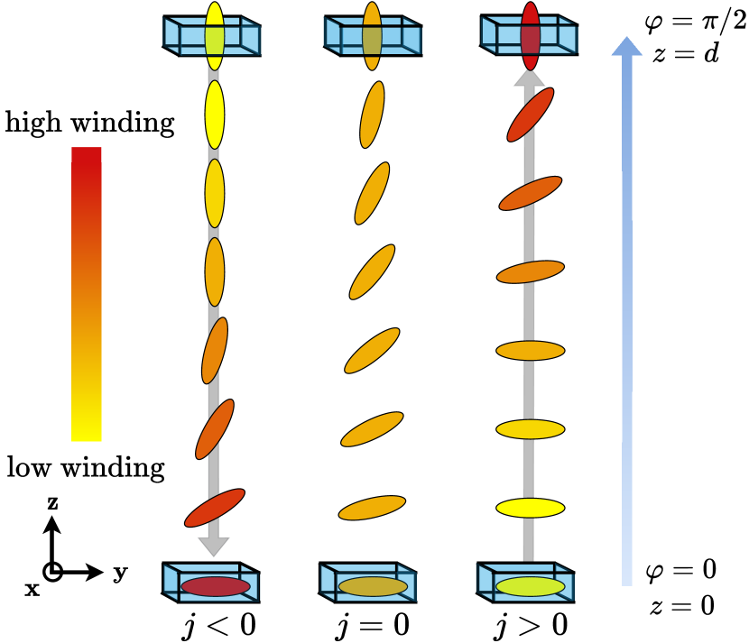
For a sufficiently slowly varying current , the solution for the nematic texture is well-approximated by the quasistatic solution. We consequently set in Eq. (1a) and parameterize the nematic texture in terms of the winding density in the plane, . Focusing on the linear response, electrostatic contributions to are not included since they are quadratic in . For a full detailed analysis, the dielectric term would be included [40, 46]. However, the effects due to the nemato-ionic coupling can always be qualitatively distinguished from e.g., the Freedericksz effect, since the former depends on the sign of while the latter does not. Equation (1a) then governs the winding density as . The coupling of current to the winding rather than to nematic orientation further distinguishes this effect from the Freedericksz effect.
Integrating Eq. (1a), the quasistatic solution for the winding density is
| (5) |
where is the length scale at which the winding density decays. Winding with are stable ground states. All other values of are metastable states since the winding can be smoothly unwound in multiples of by allowing the director to rotate out of the plane. These states can be stabilized by including easy-plane anisotropy, disallowing out-of-plane rotations. Furthermore, these metastable states can be made accessible by utilizing chiral liquid crystals. The winding density is dragged along the direction of the current flow. If , the winding density localizes at or , for positive and negative values of respectively. In these cases, the nematic texture switches between configurations that are parallel or orthogonal to the plane.
The backaction by the nematic dynamics on the electrical response induces the motive force given in Eq. (1d). In this setup, , where the angle is obtained by integrating Eq. (5) while requiring . can be formally understood as the winding flux. The motive force , which can be understood as a fictitious electric field, induces an effective potential drop between the bottom and top plates, in addition to the actual electric field . Integrating the motive force over the thickness and taking the leading term in , the instantaneous effective potential difference is
| (6) |
Fourier transforming into the frequency domain, the corresponding induced impedance of the nematic slab is
| (7) |
which has the inductive form [47]. Suppose a capacitor is filled with a slab of nematic electrolyte. Driving the capacitor with an alternating current and measuring the impedance yields the strength of the reciprocal coupling relative to elasticity . Moreover, as the integrated winding increases, so would the measured effective inductance.
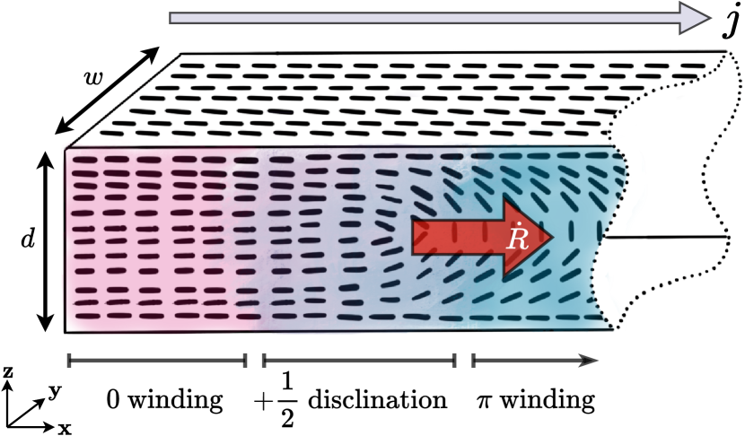
Line disclination dynamics.—In addition to boundary conditions, topological defects also imprint nontrivial nematic textures. This leads to dynamic effects when the system is subjected to an electrical current flow. As a minimal example, we study the response of a line disclination with a planar cross-section with winding number to an electrical current. Consider a nematic slab uniform in the direction with a width of , of thickness in the direction, and length in the direction larger than . On the top, bottom, and left-most face, the director is strongly anchored to point along the direction. The setup is depicted in Fig. 3.
Suppose there are two domains: a small domain with 0 winding from the bottom to the top face and a large domain in which the director uniformly undergoes winding. Transitioning from one domain to the other, we find a disclination of radius , with a line singularity along the axis. This setup has been experimentally realized by Sandford O’Neill et al. [48]. However, their focus was on controlling the defect by utilizing the electric coupling stemming from anisotropy, rather than the nemato-ionic coupling.
We will study the forces on the defect, as well as derive its terminal velocity. Approximating the defect as a “rigidly moving soliton,” we employ the ansatz [49]. In doing so, we place the time dependence of the director field into , the position of the defect core. The force on the defect is for free energy and Rayleighan . In the vicinity of the disclination, the angle of the projection of to the plane is . Here, is the polar angle relative to the axis [50]. Away from the disclination, the nematic texture will distort to match the boundary conditions.
Using the Rayleighans in Eqs. (4b)-(4c) and the free energy in Eq. (2), the force on the defect is
| (8) |
with the defect core size. The first term is a constant force due to the elastic relaxation of the nematic texture. To lower the free energy, the 0 winding domain will grow while the winding domain shrinks. The second term is a drag force on the disclination and stems from and . The dissipation function results in a core velocity-dependent drag force. , the friction between charge current and nematic texture, uses current as a handle to apply a force. Combining the Rayleighans, we find an effective Rayleighan to leading order in ,
| (9) |
describes the solitonic viscosity, with damping parameter . The generalized velocity is , the defect velocity modified by the ionic current. Instead of using and as the generalized velocities, we could instead use this collective degree of freedom in the Rayleighan.
The terminal velocity of the disclination is
| (10) |
When , agrees with previous studies for the velocity of a disclination in the absence of fluid motion [51, 50]. Measurement of can provide , parameterizing the relative strengths of the nemato-ionic coupling to the damping . The motion of the disclination can be understood as topological texture electrophoresis, in which topological textures are transported in the absence of fluid motion or suspended particles. Electric current provides a robust handle to manipulate topological defects, enabling technological applications such as microparticle transport and spatial light modulators [52, 53].
Discussion.—Thus far, we have constructed the scaffolding for future studies of dynamic phenomena as well as applications in nematronics. Moving forward, we can consider nematronic devices which exploit this coupling, with a focus on topological aspects. For example, building up winding via manipulating topological defects could lead to energy storage devices [54, 55]. Current driven transport of nematic defects for signal transport would also be an intriguing avenue of research. Nematic hedgehogs and disclinations are nonlocal topological objects [15], which makes them promising candidates for information carriers in soft matter systems [56].
From a theoretical perspective, studying these effects in different liquid crystalline phases, e.g. twist-bend nematic phases [57] and blue phases [58, 59], is a potentially interesting research direction. To elucidate the origins of , one could study the coupling microscopically rooted in interactions between ionic charge fluctuations and nematogen polarizability. In spintronics, research into driving ferromagnetic domain wall motion with spin-polarized electrical current has unraveled novel physics [60, 7, 61]. It could be fruitful to proceed along a similar line by studying the electrical response of domain walls in the nematic and ferroelectric nematic phase [62, 63, 48]. Additionally, studies on isotropic electrolytes show that solutions with multiple ion species with different valencies [64] and charged colloidal particles can lead to intriguing effects [65] that could be also studied in nematic systems.
Acknowledgements.
Acknowledgments. This work was primarily supported by the U.S. Department of Energy, Office of Basic Energy Sciences under Grant No. DE-SC0012190 (C.D. and Y.T.). J.C.E. acknowledges financial support from the Polish National Agency for Academic Exchange (NAWA) under the Ulam programme Grant No. PPN/ULM/2019/1/00257. M.R. acknowledges funding from Slovenian research agency ARRS grants P1-0099, N1-0195, and J1-2462, and EU ERC AdG LOGOS.References
- Žutić et al. [2004] I. Žutić, J. Fabian, and S. Das Sarma, Spintronics: Fundamentals and applications, Rev. Mod. Phys. 76, 323 (2004).
- Tserkovnyak [2018] Y. Tserkovnyak, Perspective: (beyond) spin transport in insulators, J. Appl. Phys. 124, 190901 (2018).
- Wolf et al. [2001] S. A. Wolf, D. D. Awschalom, R. A. Buhrman, J. M. Daughton, S. von Molnár, M. L. Roukes, A. Y. Chtchelkanova, and D. M. Treger, Spintronics: A spin-based electronics vision for the future, Science 294, 1488 (2001).
- Vedmedenko and Altwein [2014] E. Y. Vedmedenko and D. Altwein, Topologically protected magnetic helix for all-spin-based applications, Phys. Rev. Lett. 112, 017206 (2014).
- Jones et al. [2020] D. Jones, J. Zou, S. Zhang, and Y. Tserkovnyak, Energy storage in magnetic textures driven by vorticity flow, Phys. Rev. B 102, 140411(R) (2020).
- Chappert et al. [2007] C. Chappert, A. Fert, and F. N. Van Dau, The emergence of spin electronics in data storage, Nat. Mater. 6, 813 (2007).
- Parkin et al. [2008] S. S. P. Parkin, M. Hayashi, and L. Thomas, Magnetic domain-wall racetrack memory, Science 320, 190 (2008).
- Diao et al. [2007] Z. Diao, Z. Li, S. Wang, Y. Ding, A. Panchula, E. Chen, L.-C. Wang, and Y. Huai, Spin-transfer torque switching in magnetic tunnel junctions and spin-transfer torque random access memory, J. Phys. Condens. Matter 19, 165209 (2007).
- Locatelli et al. [2014] N. Locatelli, V. Cros, and J. Grollier, Spin-torque building blocks, Nat. Mater. 13, 11 (2014).
- Cornelissen et al. [2015] L. Cornelissen, J. Liu, R. Duine, J. B. Youssef, and B. Van Wees, Long-distance transport of magnon spin information in a magnetic insulator at room temperature, Nat. Phys. 11, 1022 (2015).
- Zou et al. [2020] J. Zou, S. Zhang, and Y. Tserkovnyak, Topological transport of deconfined hedgehogs in magnets, Phys. Rev. Lett. 125, 267201 (2020).
- Mermin [1979] N. D. Mermin, The topological theory of defects in ordered media, Rev. Mod. Phys. 51, 591 (1979).
- de Gennes and Prost [1993] P. de Gennes and J. Prost, The Physics of Liquid Crystals, International Series of Monographs (Clarendon Press, 1993).
- Vertogen and Jeu [1988] G. Vertogen and W. Jeu, Thermotropic Liquid Crystals, Fundamentals, Chemical Physics Series (Springer-Verlag, 1988).
- Nakahara [2003] M. Nakahara, Geometry, topology, and physics, 2nd ed., Graduate student series in physics (Institute of Physics Publishing, 2003).
- Kleman and Lavrentovich [2006] M. Kleman and O. D. Lavrentovich, Topological point defects in nematic liquid crystals, Philos. Mag. 86, 4117 (2006).
- Müller and Senior [2009] G. Müller and J. Senior, Simplified theory of Archimedean screws, J. Hydraul. Res. 47, 666 (2009).
- Ichimura et al. [1988] K. Ichimura, Y. Suzuki, T. Seki, A. Hosoki, and K. Aoki, Reversible change in alignment mode of nematic liquid crystals regulated photochemically by command surfaces modified with an azobenzene monolayer, Langmuir 4, 1214 (1988).
- Lavrentovich [2020a] O. D. Lavrentovich, Design of nematic liquid crystals to control microscale dynamics, Liq. Cryst. Rev. 8, 59 (2020a), https://doi.org/10.1080/21680396.2021.1919576 .
- Tovkach et al. [2017] O. M. Tovkach, C. Conklin, M. C. Calderer, D. Golovaty, O. D. Lavrentovich, J. Viñals, and N. J. Walkington, Q-tensor model for electrokinetics in nematic liquid crystals, Phys. Rev. Fluids 2, 053302 (2017).
- Tovkach et al. [2016] O. M. Tovkach, M. C. Calderer, D. Golovaty, O. Lavrentovich, and N. J. Walkington, Electro-osmosis in nematic liquid crystals, Phys. Rev. E 94, 012702 (2016).
- Conklin et al. [2018] C. Conklin, O. M. Tovkach, J. Viñals, M. C. Calderer, D. Golovaty, O. D. Lavrentovich, and N. J. Walkington, Electrokinetic effects in nematic suspensions: Single-particle electro-osmosis and interparticle interactions, Phys. Rev. E 98, 022703 (2018).
- Lehmann [1900] O. Lehmann, Structur, system und magnetisches verhalten flüssiger krystalle und deren mischbarkeit mit festen, Ann. Phys. (Berl.) 307, 649 (1900).
- Oswald et al. [2019] P. Oswald, A. Dequidt, and G. Poy, Lehmann effect in nematic and cholesteric liquid crystals: a review, Liq. Cryst. Rev. 7, 142 (2019).
- Madhusudana and Pratibha [1989] N. Madhusudana and R. Pratibha, An experimental investigation of electromechanical coupling in cholesteric liquid crystals, Liq. Cryst. 5, 1827 (1989).
- Svenšek et al. [2006] D. Svenšek, H. Pleiner, and H. R. Brand, Phase winding in chiral liquid crystalline monolayers due to lehmann effects, Phys. Rev. Lett. 96, 140601 (2006).
- Tabe and Yokoyama [2003] Y. Tabe and H. Yokoyama, Coherent collective precession of molecular rotors with chiral propellers, Nat. Mater. 2, 806 (2003).
- Svenšek et al. [2008] D. Svenšek, H. Pleiner, and H. R. Brand, Inverse lehmann effects can be used as a microscopic pump, Phys. Rev. E 78, 021703 (2008).
- [29] See Supplemental Material at [] for (i) the generalized theory for nematic electrolytes with hydrodynamic effects restored, (ii) expanded discussion of the artificial symmetries, and (iii) proof that flexoelectric effects can be qualitatively distinguished from the dissipative nemato-ionic coupling.
- [30] Generically, whenever the charge transport is electrically triggered, the mass transport is also automatically induced. This, in turn, generates a corresponding dissipative field acting on the nematic texture. The dissipative field and motive force stemming from the mass sector would not qualitatively affect the kinematic effects due to the charge sector and could easily be included.
- Zakharov et al. [1999] A. V. Zakharov, A. V. Komolkin, and A. Maliniak, Rotational viscosity in a nematic liquid crystal: A theoretical treatment and molecular dynamics simulation, Phys. Rev. E 59, 6802 (1999).
- Ralph and Stiles [2008] D. C. Ralph and M. D. Stiles, Spin transfer torques, J. Magn. Magn. Mater. 320, 1190 (2008).
- Tserkovnyak et al. [2002] Y. Tserkovnyak, A. Brataas, and G. E. W. Bauer, Enhanced gilbert damping in thin ferromagnetic films, Phys. Rev. Lett. 88, 117601 (2002).
- Qian and Sheng [1998] T. Qian and P. Sheng, Generalized hydrodynamic equations for nematic liquid crystals, Phys. Rev. E 58, 7475 (1998).
- Chandragiri et al. [2020] S. Chandragiri, A. Doostmohammadi, J. M. Yeomans, and S. P. Thampi, Flow states and transitions of an active nematic in a three-dimensional channel, Phys. Rev. Lett. 125, 148002 (2020).
- Hernández-Ortiz et al. [2011] J. P. Hernández-Ortiz, B. T. Gettelfinger, J. Moreno-Razo, and J. J. de Pablo, Modeling flows of confined nematic liquid crystals, J. Chem. Phys. 134, 134905 (2011).
- Leslie [1979] F. Leslie, Theory of flow phenomena in liquid crystals (Elsevier, 1979) pp. 1–81.
- Calderer et al. [2016] M. C. Calderer, D. Golovaty, O. Lavrentovich, and N. J. Walkington, Modeling of nematic electrolytes and nonlinear electroosmosis, SIAM J. Appl. Math. 76, 2260 (2016).
- Ball [2017] J. M. Ball, Mathematics and liquid crystals, Mol. Cryst. Liq. Cryst. 647, 1 (2017).
- Chandrasekhar [1992] S. Chandrasekhar, Liquid Crystals, 2nd ed. (Cambridge University Press, 1992).
- Shen and Hu [2010] S. Shen and S. Hu, A theory of flexoelectricity with surface effect for elastic dielectrics, J. Mech. Phys. Solids 58, 665 (2010).
- Gyarmati et al. [1970] I. Gyarmati et al., Non-equilibrium thermodynamics, Vol. 184 (Springer, 1970).
- Sonnet et al. [2004] A. Sonnet, P. Maffettone, and E. Virga, Continuum theory for nematic liquid crystals with tensorial order, J. Non-Newton. Fluid Mech. 119, 51 (2004).
- Onsager [1931] L. Onsager, Reciprocal relations in irreversible processes. i., Phys. Rev. 37, 405 (1931).
- Matsumoto et al. [1976] S. Matsumoto, M. Kawamoto, and K. Mizunoya, Field‐induced deformation of hybrid‐aligned nematic liquid crystals: New multicolor liquid crystal display, J. Appl. Phys. 47, 3842 (1976).
- Frisken and Palffy-Muhoray [1989] B. J. Frisken and P. Palffy-Muhoray, Freedericksz transitions in nematic liquid crystals: The effects of an in-plane electric field, Phys. Rev. A 40, 6099 (1989).
- [47] When the frequency of the AC field is comparable to the natural frequency associated with nematic dynamics, the induced impedance will have capacitative contributions in addition to inductive contributions. Capacitative contributions also arise when screening due to charge buildup at the boundaries is considered.
- Sandford O’Neill et al. [2020] J. J. Sandford O’Neill, P. S. Salter, M. J. Booth, S. J. Elston, and S. M. Morris, Electrically-tunable positioning of topological defects in liquid crystals, Nat. Commun. 11, 1 (2020).
- Thiele [1973] A. A. Thiele, Steady-state motion of magnetic domains, Phys. Rev. Lett. 30, 230 (1973).
- Imura and Okano [1973] H. Imura and K. Okano, Friction coefficient for a moving disinclination in a nematic liquid crystal, Phys. Lett. A 42, 403 (1973).
- Tang and Selinger [2019] X. Tang and J. V. Selinger, Theory of defect motion in 2d passive and active nematic liquid crystals, Soft Matter 15, 587 (2019).
- Yoshida et al. [2015] H. Yoshida, K. Asakura, J.-i. Fukuda, and M. Ozaki, Three-dimensional positioning and control of colloidal objects utilizing engineered liquid crystalline defect networks, Nat. Commun. 6, 1 (2015).
- Ghadimi Nassiri and Brasselet [2018] M. Ghadimi Nassiri and E. Brasselet, Multispectral management of the photon orbital angular momentum, Phys. Rev. Lett. 121, 213901 (2018).
- Patil et al. [2020] V. P. Patil, Ž. Kos, M. Ravnik, and J. Dunkel, Discharging dynamics of topological batteries, Phys. Rev. Res. 2, 043196 (2020).
- Tserkovnyak and Xiao [2018] Y. Tserkovnyak and J. Xiao, Energy storage via topological spin textures, Phys. Rev. Lett. 121, 127701 (2018).
- Žiga Kos and Dunkel [2022] Žiga Kos and J. Dunkel, Nematic bits and universal logic gates, Sci. Adv. 8, eabp8371 (2022).
- Jákli et al. [2018] A. Jákli, O. D. Lavrentovich, and J. V. Selinger, Physics of liquid crystals of bent-shaped molecules, Rev. Mod. Phys. 90, 045004 (2018).
- Alexander and Yeomans [2007] G. P. Alexander and J. M. Yeomans, Flexoelectric blue phases, Phys. Rev. Lett. 99, 067801 (2007).
- Castles et al. [2010] F. Castles, S. M. Morris, E. M. Terentjev, and H. J. Coles, Thermodynamically stable blue phases, Phys. Rev. Lett. 104, 157801 (2010).
- Berger [1978] L. Berger, Low-field magnetoresistance and domain drag in ferromagnets, J. Appl. Phys. 49, 2156 (1978).
- Kittel [1949] C. Kittel, Physical theory of ferromagnetic domains, Rev. Mod. Phys. 21, 541 (1949).
- Sebastián et al. [2020] N. Sebastián, L. Cmok, R. J. Mandle, M. R. de la Fuente, I. Dreven šek Olenik, M. Čopič, and A. Mertelj, Ferroelectric-ferroelastic phase transition in a nematic liquid crystal, Phys. Rev. Lett. 124, 037801 (2020).
- Lavrentovich [2020b] O. D. Lavrentovich, Ferroelectric nematic liquid crystal, a century in waiting, Proc. Natl. Acad. Sci. U.S.A. 117, 14629 (2020b).
- Warren [2020] P. B. Warren, Non-Faradaic electric currents in the nernst-planck equations and nonlocal diffusiophoresis of suspended colloids in crossed salt gradients, Phys. Rev. Lett. 124, 248004 (2020).
- Avni et al. [2019] Y. Avni, D. Andelman, and R. Podgornik, Charge regulation with fixed and mobile charged macromolecules, Curr. Opin. Electrochem. 13, 70 (2019).