Tuning the magnetic interactions in van der Waals Fe3GeTe2 heterostructures:
A comparative study of ab initio methods
Abstract
We investigate the impact of mechanical strain, stacking order, and external electric fields on the magnetic interactions of a two-dimensional (2D) van der Waals (vdW) heterostructure in which a 2D ferromagnetic metallic Fe3GeTe2 monolayer is deposited on germanene. Three distinct computational approaches based on ab initio methods are used, and a careful comparison is given: (i) The Green’s function method, (ii) the generalized Bloch theorem, and (iii) the supercell approach. First, the shell-resolved exchange constants are calculated for the three Fe atoms within the unit cell of the freestanding Fe3GeTe2 monolayer. We find that the results between methods (i) and (ii) are in good qualitative agreement and also with previously reported values. An electric field of V/Å applied perpendicular to the Fe3GeTe2/germanene heterostructure leads to significant changes of the exchange constants. We show that the Dzyaloshinskii-Moriya interaction (DMI) in Fe3GeTe2/germanene is mainly dominated by the nearest neighbors, resulting in a good quantitative agreement between methods (i) and (ii). Furthermore, we demonstrate that the DMI is highly tunable by strain, stacking, and electric field, leading to a large DMI comparable to that of ferromagnetic/heavy metal (FM/HM) interfaces, which have been recognized as prototypical multilayer systems to host isolated skyrmions. The geometrical change and hybridization effect explain the origin of the high tunability of the DMI at the interface. The electric-field driven DMI obtained by method (iii) is in qualitative agreement with the more accurate ab initio method used in approach (ii). However, the field-effect on the DMI is overestimated by method (iii) by about 50%. This discrepancy is attributed to the different implementations of the electric field and basis sets used in the ab initio methods applied in (ii) and (iii). The magnetocrystalline anisotropy energy (MAE) can also be drastically changed by the application of compressive or tensile strain in the Fe3GeTe2/germanene heterostructure. The application of an electric field, in contrast, leads only to relatively small changes of the MAE for electric fields of up to 1 V/Å.
I Introduction
Magnetic skyrmions [1] – topologically protected chiral spin structures with particle-like properties – have attracted tremendous attention due to their potential application in next-generation spintronics devices such as racetrack memories [2], logic gates [3], artificial synapses for neuromorphic computing [4], and qubits for quantum computing [5]. The formation of magnetic skyrmions is due to the competition between the Heisenberg exchange and Dzyaloshinskii-Moriya interaction (DMI) [6, 7, 8, 9] together with the magnetocrystalline anisotropy energy (MAE). In particular, the DMI plays an essential role in stabilizing skyrmions since it favors canted spin configurations with a unique rotational sense. The DMI results from spin-orbit coupling and is only non-zero for systems with broken inversion symmetry. Magnetic skyrmion lattices were discovered in experiments on bulk chiral magnets [10, 11] and subsequently in epitaxial ultrathin films [12]. Isolated magnetic skyrmions were observed in ultrathin transition-metal films at low temperatures [13, 14, 15] and at room temperature in magnetic multilayers [16, 17, 18, 19], in ferrimagnets [20], and in synthetic antiferromagnets [21].
Recently, long-range magnetism was reported in two-dimensional (2D) materials [22, 23, 24]. This provides a promising alternative avenue for exploring topological spin structures in atomically thin layers. Several recent experiments reported the observation of skyrmions in 2D vdW heterostructures, such as at an Fe3GeTe2/WTe2 interface [25], in a Fe3GeTe2/Co/Pd multilayer [26], and at an Cr2Ge2Te6/Fe3GeTe2 interface [27]. Moreover, magnetic domain walls [28] and nonreciprocal magnons [29] were reported in the Fe3GeTe2 surface. The origin of skyrmions in these systems was attributed to the interfacial DMI. A comprehensive material survey has been done by ab initio calculations to explore the DMI in 2D magnets. The family of monolayer Janus vdW magnets has been predicted to possess large enough DMI to allow stable skyrmions [30, 31, 32, 33, 34, 35]. Néel-type magnetic skyrmions were also observed in Fe3GeTe2 crystals, and attributed to the DMI due to oxidized interfaces [36]. In addition, it has been proposed that skyrmions can be stabilized in 2D vdW multiferroic heterostructures [37], Moiré of vdW 2D magnets [38], and even in centrosymmetric materials [39] induced by exchange frustration. For most 2D magnets, the DMI is absent due to inversion symmetry. It is possible to break the inversion symmetry by designing various 2D vdW heterostuctures and applying an electric field, or strain [40, 41]. This indicates the possibility of tuning DMI via external stimuli in 2D vdW heterostuctures.
From the theoretical point of view, the calculation of the DMI at the ab initio level is, in principle, relatively straightforward, nevertheless, complications can arise in practice. Several approaches have been introduced based on different first-principles methods and used by numerous groups to calculate the DMI for various material classes [9, 42, 43, 44, 45, 46, 47, 48, 49, 50, 51, 52, 53, 30]. Unfortunately, mostly without a sufficient cross-check between them. This invites a detailed benchmark study to validate different approaches, however, so far this has only been performed for the ultrathin film system of a Co monolayer on Pt(111) [54]. Such comparative studies are crucial to understanding the origin of skyrmion stability, particularly for the newly discovered 2D magnets.
Here, using ab initio calculations, we compare systematically three current state-of-the-art approaches to extract magnetic interaction parameters in Fe3GeTe2 (FGT) based heterostructures, namely (i) by the Green’s function method [55], (ii) by using the generalized Bloch theorem (gBT) [56, 57, 43, 54], or (iii) by using the supercell approach [49]. First we study the shell-resolved exchange interaction between the Fe atoms of the different layers in a freestanding FGT monolayer. We find that the approaches (i) and (ii) are in good qualitative agreement. We then focus on the structural and magnetic properties of the 2D vdW heterostructure of an FGT monolayer deposited on germanene under strain, stacking, and electric field. We find that a small compressive strain () of about 3% can significantly enhance the DMI in FGT heterostructures by more than 400% compared to the value without strain. The variation of DMI is mainly due to the geometrical change of the FGT monolayer. Such a large DMI is comparable to that in state-of-the-art FM/HM heterostructures, which have been demonstrated as prototypical multilayer systems to host individual skyrmions even at room temperature. Furthermore, the DMI can be substantially modified via different stacking geometry due to the hybridization effect at the interface.
Upon applying an electric field the strength of the DMI varies almost linearly and can even change sign when a strong electric field ( 1 V/Å) is applied. The exchange constants are also considerably modified due to an electric field while the effect on the magnetocrystalline anisotropy energy (MAE) is small. However, the MAE is dramatically reduced to 25% of its original value at a compressive strain of . In connection with the exchange frustration in FGT/germanene these large changes of DMI and MAE open the possibility of zero-field magnetic skyrmions [58]. For the DMI in FGT/Ge, the three theoretical approaches are in good qualitative agreement, and we also discuss quantitative comparison in detail.
The paper is organized as follows. In Sec. II, we describe the three theoretical approaches used to obtain the relevant spin-spin interaction parameters by mapping the ab initio DFT calculations onto an extended Heisenberg model. In Sec. III, we examine the Heisenberg exchange for free-standing FGT followed by the DMI and MAE for FGT heterostuctures. Different theoretical approaches are carefully benchmarked. We further investigate the effects of biaxial strain, stacking configuration as well electric field on the magnetic interactions in FGT heterostuctures. Finally, we summarize our main conclusions in Sec. IV.
II Methods and computational details
In order to describe the magnetic properties of FGT heterostructures, we use the extended Heisenberg model for the spins of Fe atoms in the hexagonal structure:
| (1) |
where and are normalized magnetic moments at positions and respectively. The three magnetic interaction terms correspond to the Heisenberg isotropic exchange, the DMI, and the MAE, respectively, and they are characterized by the parameters , , and in the related terms. Note, that by using Eq. (1) it is assumed that the magnetic moments are constant.
During the past decade, in order to obtain the parameters very accurately in Eq. (1), several approaches based on density functional theory (DFT) have been developed, which is frequently named ab initio atomistic spin model. In this work, we apply three different approaches for the calculation of magnetic interactions in FGT vdW heterostructures: (i) The Green’s function method [55, 59] (also known as the Liechtenstein formula) employing infinitesimal rotations; (ii) The generalized Bloch theorem (gBT) [56] which allows calculating the total energy of spin-spirals of any wave vector in magnetic nanostructures [57]; (iii) The supercell approach [49] which is straightforward but computationally heavy due to the comparison of total energies in a supercell geometry. We performed DFT calculations using two community ab initio codes which differ in their choice of basis set: The QuantumATK (QATK) package [60] uses an expansion of electronic states in a linear combination of atomic orbitals (LCAO) while the FLEUR code [61] is based on the full-potential linearized augmented plane wave (FLAPW) formalism. The former is computationally very efficient, while the latter ranks amongst the most accurate implementations of DFT. In the following, we denote the three different approaches as LCAO-Green, FLAPW-gBT, and LCAO-supercell for simplicity. Apart from the methods presented above, there are also other approaches widely used in the community for calculations of spin-spin interactions, e.g., the four-state method [62] and the machine learning approach [63].
II.1 The Green’s function method: LCAO-Green
Throughout this paper, vectors are denoted with bold characters while matrices are represented by bold plus single underline (e.g., ). Moreover, represent orbital index while is spin index.
The variation of total energy due to the spin interactions in Eq. 1, we obtain the following variation with respect to the and :
| (2) |
where the first term represents the isotropic exchange (i.e., Heinsenberg), the second term is the the symmetric anisotropic exchange, where is a symmetric tensor. The last term corresponds to the DMI,
Green’s function method treats the local rigid spin rotation as a perturbation. Using the force theorem, the total energy variation due to the two-spin interaction between sites and is
| (3) |
where and are real-space Hamiltonian and Green’s function. Here, is a unit orientation vector (normalized to 1).
Then, in Eq. 3, if we take trace in both orbital () and spin space (), we end up with the following expression:
| (4) |
To simplify for the notation of Eq. 4, we define a central quantity for the Green function method, namely the matrix, which has a size as follows.
| (5) |
where indices and run over 0, , , or .
Finally, comparing Eq. 4 to Eq. 2, the Heisenberg exchange and the DMI can be expressed by using only the matrix as follows.
| (6) |
| (7) |
| (8) |
where is the on-site difference between the spin-up and -down part of the Hamiltonian matrix.
If we neglect SOC, the DMI vanishes, , , , we arrive at the original Liechtenstein-Katsnelson-Antropov-Gubanov (LKAG) formula [55] which was proposed in 1987,
| (9) |
where becomes hermitian.
Note that the derivations above are general for orthogonal and non-orthogonal basis sets. Please refer to Ref. [64] for a detailed demonstration within the non-orthogonal basis set.
Our Green’s function calculations were performed using QATK [60] in two steps: (i) We performed LCAO-DFT calculations with SOC in order to construct the tight-binding like Hamiltonian matrix and the overlap matrix . (ii) The magnetic exchange parameters were evaluated as described above by Eqs. (3-9). For LCAO-DFT calculations on FGT monolayers and on FGT/Ge heterostructures, the energy cutoff for the density grid sampling was set to 150 Hartree, and a -point mesh was adopted for the Brillouin zone (BZ) integration. For magnetic exchange calculations, we used a much denser -point mesh of , 60 circle contour points, and 13 nearest neighbors (NN) in order to obtain accurate numerical integration. Using these parameters, we extracted and parameters with an accuracy of 0.01 meV. Note that this approach, i.e., infinitesimal spin rotations, fits well to magnetic skyrmions in which we often have large noncollinear spin structures.
II.2 The generalized Bloch theorem: FLAPW-gBT
The second approach employs the FLAPW method as implemented in the FLEUR code [61] and is based on the generalized Bloch theorem (gBT) [56, 57]. It allows considering spin-spirals of any wave vector for systems without SOC. We first self-consistently compute within the scalar-relativistic approximation the energy dispersion, , of homogeneous flat spin spirals [57] which are characterized by a wave vector and an angle between adjacent magnetic moments separated by lattice vector .
As a second step, the DMI is computed within first-order perturbation theory on the self-consistent spin spiral state [43, 46, 54]. The energy variation of these states due to the SOC Hamiltonian can be written as
| (10) |
where are the self-consistent solutions in the scalar-relativistic approximation, is the Bloch vector, and is the band index. By integration over the Brillouin zone and summation over all occupied bands this gives the total energy contribution for spin spirals due to SOC denoted as .
We map the energy dispersion in the scalar-relativistic approximation, , and the energy contribution to spin spirals due to DMI, , to the atomistic spin model, Eq. (1), in order to extract the exchange constants, , and the magnitudes of the , respectively. One of the key advantages of the gBT approach is that even incommensurate spin spirals and those with a large can be treated very efficiently in the chemical unit cell, i.e., without the need for large supercells.
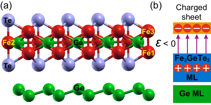
We used a cutoff parameter for the FLAPW basis functions of = 4.0 a.u.-1, and we included basis functions including spherical harmonics up to = 8. The muffin tin radii used for Fe, Ge, and Te are 2.10 a.u., 2.10 a.u., and 2.63 a.u., respectively. Moreover, we treated 3, 3 and 4 states by local orbitals for Fe and Te, respectively. To extract the and parameters, we converge the total energy of flat spin-spiral states (without SOC and with one-shot SOC) using a -point mesh. For conical spin spiral calculations, we increased the -point mesh up to since the energy dispersion amplitude is much smaller than for the flat ones. We model the effect of a uniform electric field by placing a charged sheet in the vacuum region of FGT/Ge (see Fig. 1), i.e. using the same methodology and sign convention of the electric field as in Ref. 65. We maintain the charge neutrality of the whole system by adding or removing the same amount of opposite charge to or from the interface. Finally, we computed the MAE using the force theorem using a denser -mesh of 64 64.
II.3 The supercell approach: LCAO-supercell
In this approach, the DMI within the nearest-neighbor approximation for a specific system is calculated from the energy difference between a clockwise (CW) and a counterclockwise (CCW) 90∘ spin spiral calculated within a supercell. can be obtained by the following formula [49]:
| (11) |
The corresponding micromagnetic DMI coefficient, ,
| (12) |
where and are the lattice constant and number of ferromagnetic layers, respectively.
Note, that by varying the supercell size one can go beyond nearest-neighbor DMI approximation. However, the computational effort is much larger than using the spin spiral approach sketched above.
We used the QATK code [60] and a supercell where first neighbor spins rotated as 90∘. A -point mesh was adopted for the BZ integration. We included the effect of SOC self-consistently. Although the supercell approach is straightforward and SOC can be treated self-consistently, it is only limited to very large wave vectors.
III Results and discussions
Throughout the paper, we use the following conventions. We use a minus sign in the Heisenberg exchange terms (cf. Eq. (1)), meaning that () favors ferromagnetic (antiferromagnetic) alignment between moments and . For the DMI constants, a positive (negative) sign denotes a preferred CW (CCW) rotational sense. In addition, without specification, we give in our work the in-plane component of the DMI since the out-of-plane component has shown to be negligible forming skyrmions in 2D magnets [30, 66]. All effective quantities, such as the Heisenberg exchange, the DMI, and the MAE, are measured in meV/unit cell. Note that there are 3 Fe atoms per unit cell of FGT (Fig. 1).
III.1 Geometric properties
We consider FGT heterostructures in which an FGT monolayer is deposited on germanene (denoted as FGT/Ge in the following). As shown in Fig. 1(a), FGT adopts the space group (194) P63/mmc and can be seen from the perspective of the atomistic spin model as a stack of three Fe hexagonal layers in hcp stacking. In the following, the top, center, and bottom (interface) atoms are denoted as Fe3, Fe2, and Fe1, respectively.
The motivation behind the use of germanene as a nonmagnetic layer is as follows. We recently demonstrated that the buckled structure of germanene could enhance the structural asymmetry of FGT under strain [58]. More importantly, such an efficient strain-driven DMI control is general for FGT heterostructures with buckled substrates (e.g., silicene, antimonene). On the other hand, in experiments, FGT/graphene [67], and FGT/hBN [68] have been experimentally synthesized. Since germanene is very similar to graphene in many aspects, the FGT/Ge interface is expected to be feasible.
We have used the QATK code with plane-wave basis sets for the atomic relaxation. We employed the generalized gradient approximation (GGA), obtaining a relaxed lattice constant of 4.00 Å for the Fe3GeTe2 monolayer, which is in good agreement with experimental data ranging between about 3.991 4.03 Å [69, 70]. Then, germanene is matched at the interface with FGT with a lattice mismatch smaller than 1%. The structures were fully relaxed until the energy and the forces on each atom were less than 10-8 Ry and 10-4 Ry/Bohr, respectively. We also took into account van der Waals interactions using semi-empirical dispersion corrections as formulated by Grimme [71]. We used the local density approximation (LDA) for the magnetic calculations with LCAO basis sets. We did not take into account Hubbard correction since LDA yields a magnetic moment of 1.76 /Fe that compares well with experiments, as previously pointed out in Ref. 72, 24. It has been shown recently by S. Ghosh et al. that using DFT+ leads to a less favorable description of the magnetic properties for the FGT family [73]. The lowest-energy stacking configuration is the one where the Te atom is right above the center of the hexagonal ring of germanene with an optimized vdW gap of about 2.86 Å (see Fig. 1b), which agrees well with previous results [74].
III.2 Free-standing FGT monolayer: Heisenberg exchange

Let us first consider the Heisenberg pair-wise exchange in the free-standing FGT monolayer (Fig. 2). Here, due to the lack of broken inversion symmetry, Fe3 and Fe1 are equivalent. Therefore, we end up with four different spin pairs, and , sorted by intra- and inter-layer exchange interactions. We show in Fig. 2 the Heisenberg exchange constants () with respect to distance () computed by the Green’s function method. All decrease quickly with distance, some showing an oscillatory character. The intralayer interactions (Fig. 2(a,b)) favor antiferromagnetic (AFM) coupling with moderate strength of the nearest-neighbor exchange constants meV and meV while the interlayer exchange (Fig. 2(c,d)) favor much stronger ferromagnetic (FM) coupling with meV and meV. In particular, the competition between FM and AFM pairs yields geometric frustration in a triangular sublattice, which can help to stabilize noncollinear spin structures [75, 76, 77, 78]. Clearly, the most significant exchange coupling originates from the interaction between Fe3 and Fe1 atoms, which are on top of each other (cf. Fig. 1). It drops quickly to a small negative value, i.e., AFM coupling, at the second nearest distance and goes up again to a small positive value at the third nearest distance (Fig. 2(d)). Similar results have been reported for FGT bulk [79].
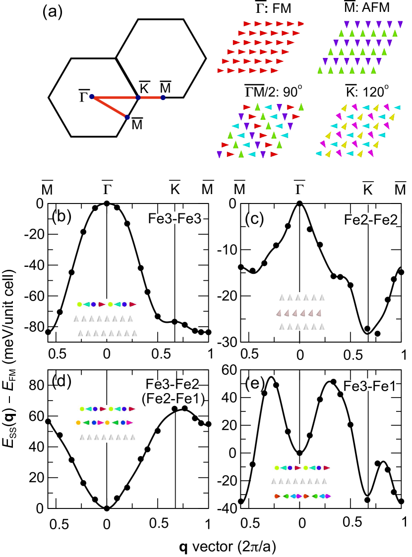
In order to quantitatively compare the results presented above with different DFT approaches, we have calculated the exchange constants also by the FLAPW-gBT method. In Fig. 3, we present the energy dispersions of flat homogeneous spin spirals (per unit cell) for a free-standing FGT monolayer. The energy dispersions are calculated in scalar-relativistic approximation, i.e. neglecting SOC, along the high symmetry directions and of the two-dimensional (2D) hexagonal Brillouin zone (BZ). The high-symmetry points represent special states: the point corresponds to the FM state, the point to the row-wise AFM state, the to the 90∘ spin spiral, and the point to the Néel-state with 120∘ between adjacent spins (Fig. 3(a)).
We focus first on intralayer exchange interactions. To extract only the Fe3-Fe3 exchange parameter, we rotate only Fe3 spins by fixing the Fe2 and Fe1 layers to the FM state (inset of Fig. 3(b)). The lowest energy for spin spirals in the Fe3 layer is at the point (Fig. 3(b)), indicating an AFM Fe3-Fe3 coupling in a good agreement with corresponding LCAO-Green calculations (cf. Fig. 2(a)). The FM state ( point) is about 83 meV/Fe atom higher in energy.
In the case of the Fe2-Fe2 pair, the direct calculation of flat spin spiral curves propagating only in the Fe2 layer is technically unfeasible due to the complete quenching of the magnetic moment on the Fe2 atom due to symmetry (for details, see Appendix B). This shows that the magnetic moment of Fe2 is only induced by the magnetic moments of Fe1 and Fe3 in the ferromagnetic state. Therefore, we used conical spin spirals with a small cone angle of , i.e. close to the FM state, and transformed the obtained energy dispersion back to a flat spin spiral: . As shown in Fig. 3(c), the energy dispersion for the Fe2 layer becomes qualitatively different compared to the Fe3 layer: The ground state is found to be at the point (Néel state). The energy difference between FM and Néel state is much smaller than in the case of Fe3-Fe3, resulting in a weaker AFM Fe2-Fe2 coupling (see Table 3 in Appendix A).
To calculate the interlayer exchange interaction, i.e. between Fe3 and Fe2 atoms, we rotate the spins of the Fe3 and Fe2 layers simultaneously by fixing the Fe1 atom to the FM state (Fig. 3(d)). Then, we remove the intralayer contribution by calculating (not shown). The FM state at the point turns out to be the state of lowest energy, and the dispersion rises quickly for spin spirals with increasing , resulting in a strong FM coupling which is consistent with the LCAO-Green result (see Fig. 2(c)).
| Fe3-Fe3 | Fe2-Fe2 | Fe3-Fe1 | Fe3-Fe2 | /Fe | |
|---|---|---|---|---|---|
| LCAO-Green | 73.16 | 18.08 | 1.79 | ||
| FLAPW-gBT | 84.37 | 16.50 | 1.76 | ||
| VASP-ML [80] | 74.1 | 39.4 | 1.66 |
In contrast, the energy dispersion of spin spirals propagating only in the Fe1 and Fe3 layers looks very different (Fig. 3(e)). The energy minimum is located at the point, and two maxima are observed in the and in the directions, indicating an AFM coupling. At first glance, this seems like a qualitative difference to the result of a strong ferromagnetic Fe3-Fe1 coupling observed in the LCAO-Green calculation (Fig. 2(d)). However, this is due to the fact that the Fe3 and Fe1 atoms are on top of each other, and are not distinguishable by spin spirals which propagate in-plane with respect to the Fe layers. As a result, if we fit the spin spiral curve in Fig. 3(d), we obtain the shell-resolved exchange constants between the Fe3 and Fe1 atoms, i.e. , , , etc., except for the nearest-neighbor term, , which arises from direct Fe3-Fe1 coupling. To include explicitly, we have performed an additional calculation with an AFM coupling between the Fe3 and Fe1 atoms. After that, by comparing the total energies between FM and AFM, we can obtain by counting the number of nearest-neighbor atoms, . The obtained value for the nearest-neighbor Fe3-Fe1 coupling is meV, showing a strong FM as expected. All values for the calculated magnetic interactions up to the seventh NN are given in Appendix A.
Our main results on the exchange constants obtained by the two computational approaches are summarized in Table 1. For comparison, the results from a machine learning approach (denoted as VASP-ML) calculated by Xu et al. [80] are also included. For simplicity, we compare for all Fe-Fe pairs only the NN exchange constant. LCAO-Green, FLAPW-gBT, and VASP-ML data are in excellent qualitative agreement. Quantitatively, LCAO-Green yields exchange parameters very close to the corresponding FLAPW-gBT calculation. In particular, the Fe2-Fe2 pair agrees surprisingly well ( as compared to meV), which indicates that the conical spin spirals used in FLAPW-gBT are very close to the Green’s function method (FM state).
However, the energies of Xu et al. [80] have non-negligible discrepancy. In particular, the Fe2-Fe2 and Fe3-Fe2 pairs are about 50% higher than our FLAPW-gBT results. Reasons for this quantitative discrepancy may be the different lattice constants and different relaxations of atomic positions. Moreover, such a discrepancy might be related to the rather large higher-order exchange interactions (HOI) which have been obtained for the monolayer of FGT in Ref. 80. Note, that the energy dispersions of spin spirals include implicitly contributions from HOI which are effectively mapped to our calculated exchange constants as discussed in detail in Ref. 81. Finally, we note that DFT+ [82] significantly underestimates the exchange parameters for the FGT monolayer compared to our DFT level calculations.
III.3 FGT/Ge: Dzyaloshinskii–Moriya interaction
We now turn our discussion to the DMI, which plays a central role for the emergence of non-collinear spin structures such as magnetic skyrmions. The DMI originates from SOC, and it only exists in materials lacking inversion symmetry. According to Moriya’s symmetry rules [6], since the FGT has a (001) mirror plane, for each pair of NN Fe atoms is perpendicular to their bonds [83]. Therefore, can be expressed as
| (13) |
where being the unit vector between sites and and indicating normal to the plane.
The in-plane component of the DMI constant in the NN approximation, , can be directly obtained from the supercell approach [84] (see Eq. (11)). The perpendicular component, , does not play a significant role in 2D magnets, as reported in Ref. 30, 66, and is thus neglected. In the following, without specification, our calculated DMI refers to the in-plane DMI component, and denotes a CCW (CW) rotational sense.
For free-standing FGT, the DMI involving either Fe1 or Fe3 have opposite signs (i.e., chirality) because of the (001) mirror plane. Upon incorporating germanene in FGT, the inversion symmetry breaking at the FGT/Ge interface gives rise to an emergent DMI. Since the DMI is a key ingredient for the formation of skyrmions, methods for efficiently controlling and manipulating the DMI are essential for designing novel functional spintronics devices. We will show in the following three ways for tuning the DMI in FGT/Ge.
III.3.1 Strain
Strain engineering is one of the most commonly used methods to tune the properties of 2D layers. We study the strain-dependent DMI in FGT/Ge. The in-plane biaxial strain is defined as
| (14) |
where and are the strained and unstrained lattice constants of the FGT, respectively. For biaxial biaxial strain (), the in-plane lattice tends to increase while for tensile compressive strain () the in-plane lattice exhibits a decreasing trend.
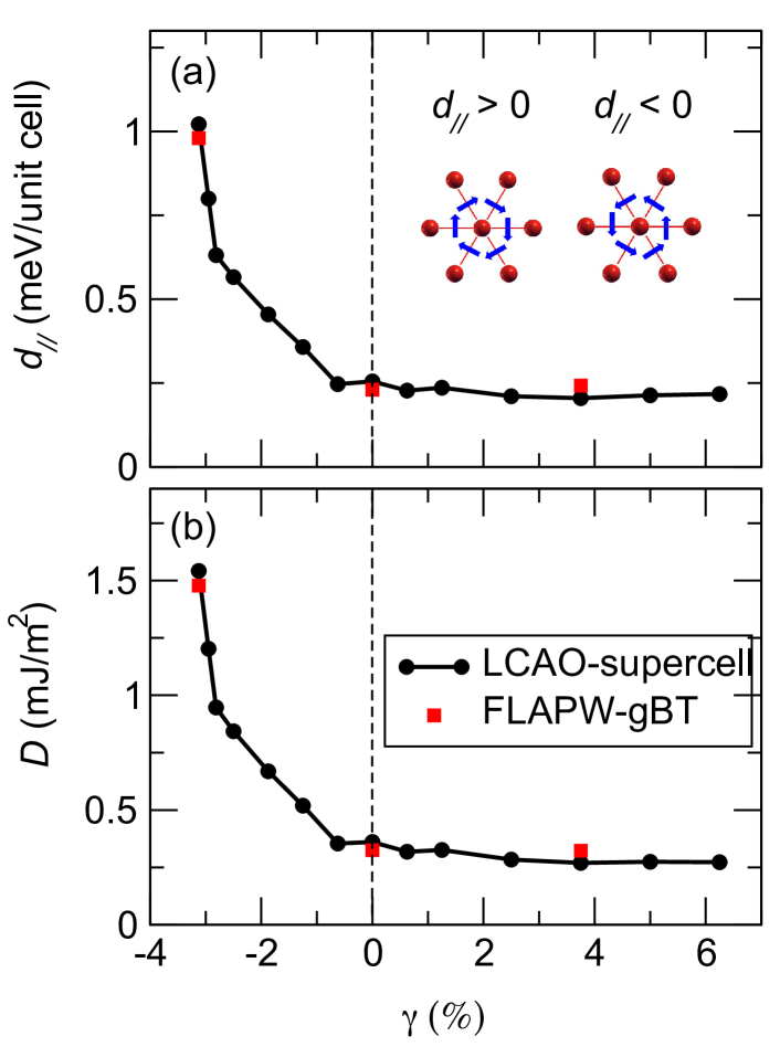
The calculated microscopic and micromagnetic of DMI for FGT/Ge are shown in Fig. 4. The DMI is evaluated quantitatively by calculating the self-consistent total energy of cycloidal spin spirals with opposite rotational sense, namely using the supercell approach (i.e., LCAO-supercell). Both compressive and tensile strains are considered ranging from 3% to 6.25%. Note that FGT has been demonstrated to be stable under such strain via DFT phonon spectrum calculations [85]. We emphasize that the value of Å used in this work was evaluated by the GGA and is slightly larger than the lattice constant calculated by LDA, Å. If we use the latter as a reference, the largest compressive strain used in this work becomes less than 1%. At equilibrium (), we find a moderate DMI of about meV, favoring a CW spin rotation. Its corresponding micromagnetic DMI coefficient is about = 0.36 mJ/m2. This value is comparable to that of the two FGT heterostructures: FGT/In2Se3 [86] (0.28 mJ/m2) and FGT/Cr2Ge2Te6 [27] (0.31 mJ/m2), which were demonstrated recently as promising vdW heterostructures to stabilize skyrmions.
Even more interestingly, we find a significant increase in the DMI when a small compressive strain is applied (Fig. 4). The extracted is about 1.5 mJ/m2 at , which is comparable to the value previously estimated in FM/HM thin-film systems [49, 18]. Such a large DMI indicates that the FGT/Ge heterostructure can be a promising interface for stable isolated skyrmions [58]. A more detailed analysis shows that the enhancement of the DMI in FGT/Ge is mainly medicated by the geometrical change due to the buckled structure of germanene as shown in Sec. III.3.2.
The results presented above are reproduced by FLAPW-gBT if we calculate the effective DMI from spin spiral calculations including SOC (red squares in Fig. 4). Here, the effective DMI constant is obtained from fits in the region of low around the FM state ( point) where the energy contribution due to SOC varies linearly with . Interestingly, the DMI predicted by the LCAO-supercell method is in excellent quantitative agreement with the one calculated by FLAPW-gBT, showing that the reported results are robust against different approaches used. This indicates a possibility of strain control of magnetic skyrmions in these systems. In contrast, a tensile strain () has almost no effect on the DMI (Fig. 4).
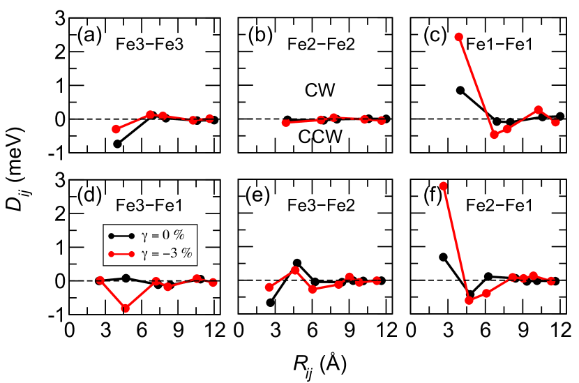
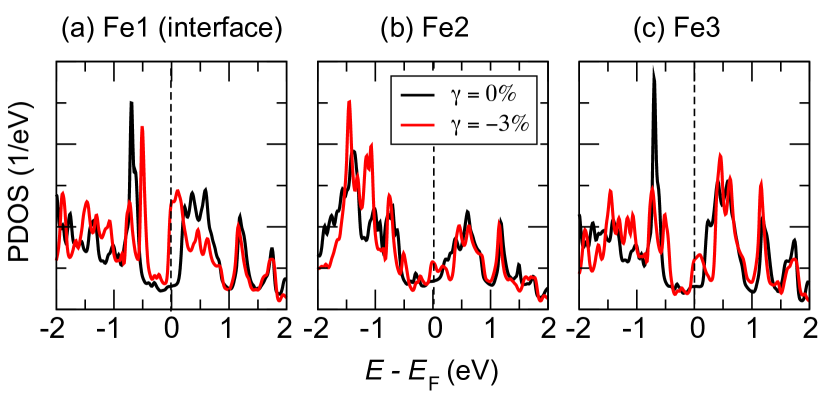
To gain further insight into the local decomposition of the DMI, we show in Fig. 5 the calculated DMI using the LCAO-Green approach for six possible Fe pairs in FGT/Ge as a function of distance with and without strain. Evidently, the external compressive strain ( %) has a significant effect on the DMI of the FGT monolayer, particularly for pairs connected to the interface Fe1 atom. When the strain is applied, a strong enhancement of the DMI favoring a CW (i.e., positive sign) rotational sense is clearly observed for Fe1-Fe1 and Fe2-Fe1 pairs (Fig. 5c,f), indicating a strong modification of electronic and magnetic properties at the interface. This is also reflected by the projected density of states in FGT/Ge (see Fig. 11 in Appendix C).
Quantitatively, the nearest-neighbor DMI changes from 0.88 (0.72) meV to 2.46 (2.84) meV for the Fe1-Fe1 (Fe2-Fe1) pair. A similar behavior is also observed for the second-nearest neighbor DMI in Fe3-Fe1 (Fig. 5d). The DMI changes from 0.1 meV to 0.80 meV, accompanying a sign change. On the other hand, Fe3-Fe3 and Fe3-Fe2 (Figs. 5(a,e) are much less affected by the strain. Moreover, due to symmetry, the DMI in Fe2-Fe2 (Fig. 5(b)) and the nearest neighbor Fe3-Fe1 (on top of each other) are almost quenched. These results are also in agreement with those obtained by the TB2J code [87] which uses a similar methodology.
| V/Å | 23.73 | 0.48 | 1.12 | 0.00 | 0.31 | 0.09 | 0.00 | 0.00 | |||||||
| 0.0 V/Å | 22.87 | 0.43 | 1.25 | 0.00 | 0.23 | 0.10 | 0.00 | 0.00 | 0.00 | 0.00 | 0.00 | ||||
| V/Å | 22.35 | 0.38 | 1.30 | 0.06 | 0.14 | 0.08 | 0.00 | 0.00 |
III.3.2 Stacking
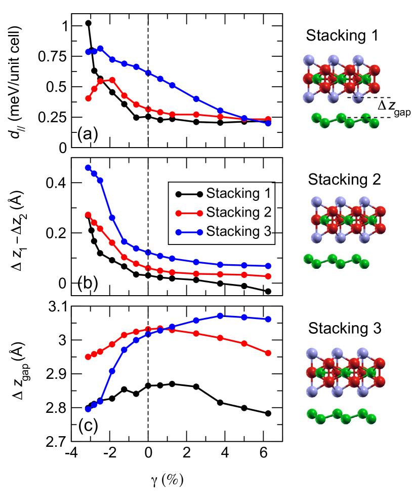
To study the effect of stacking order on the DMI of the FGT/Ge heterostructure, three fully optimized representative stacking geometries are considered here (see sketches in Fig. 6): (i) stacking 1 (the most favorable stacking geometry), in which the Te atom is right above the center of the hexagonal ring of germanene, (ii) stacking 2, in which the Ge atom of FGT is located above the center of the hexagonal ring of germanene, and (iii) stacking 3, in which the Fe1 and Fe3 atoms of FGT are placed directly above the center of the hexagonal ring of germanene.
Fig. 6(a) shows the variation of the DMI strength with respect to strain for these three stacking geometries. We observe a similar behavior for stackings 1 and 2 for the range of between about 2% to 6%, namely, a clear enhancement of DMI at compressive strain () and a nearly constant value for a tensile strain (). Interestingly, when , the DMI increases for stacking 1 while it decreases for stacking 2.
To understand the origin of the variation of the DMI, we plot in Fig. 6(b-c) the geometrical change by strain. As a negative strain is applied, increases rapidly for both stackings 1 and 2, where and denote the vertical distances between Fe1-Fe2 and Fe2-Fe3. This leads to an increase in the degree of structural asymmetry, resulting in an enhancement of the DMI. On the other hand, the vdW gap induced by hybridization is decreased by strain and is more pronounced for stacking 2 than for stacking 1. As analyzed in detail in Ref. [58], the hybridization effect for FGT/Ge decreases the DMI. This explains why the DMI for stacking 2 is smaller than for stacking 1 for .
For stacking 3, we observe the most pronounced geometrical changes, the variation of and are almost two times and three times larger than for stacking 1, respectively. As a result, even at the DMI for stacking 3 is about meV, which is 2.5 times higher than the corresponding DMI in stacking 1. However, only a slight increase of the DMI up to about meV is observed with compressive strain. Herein, the increase of is mainly due to the interplay between the increase of and the decrease of , which have an opposite effect on the DMI. By applying a tensile strain to the system, the DMI decreases nearly linearly for stacking 3.
III.3.3 Electric field
The FLAPW method in film geometry as implemented in the FLEUR code is used to include the effect of an external electric field as described in Ref. 88. An out-of-plane electric field is defined by adding a charge plate in the vacuum and adding the same amount of opposite charge to FGT/Ge (cf. Fig. 1) to maintain charge neutrality [88, 89, 65]. We chose electric field values of V/Å, which can be applied in scanning tunneling microscopy experiments [90] and allow to write and delete isolated magnetic skyrmions in ultrathin transition-metal films as demonstrated experimentally [90] and based on atomistic spin simulations with DFT parameters [65, 91]. Note, that we use the same sign convention for the electric field as in Refs. 65, 91.
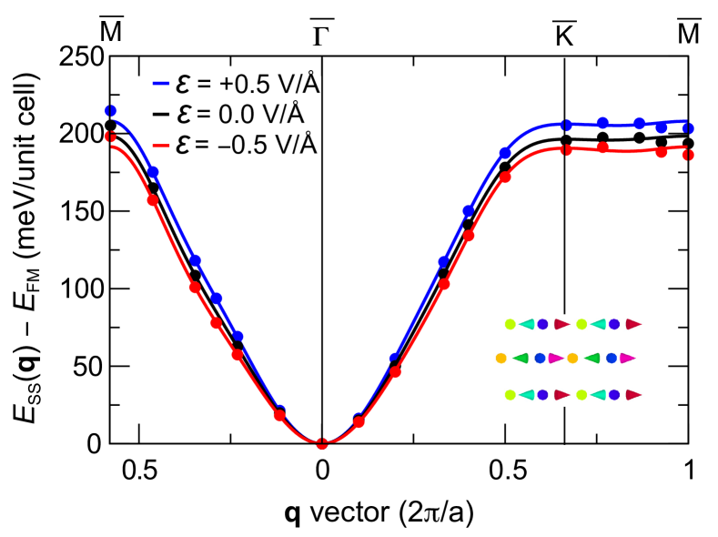
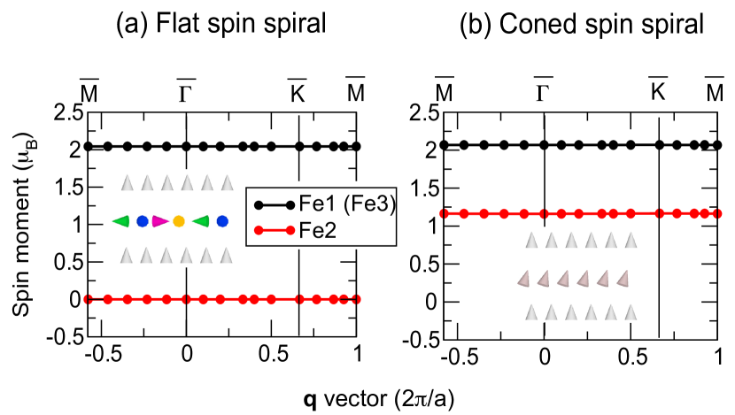
We show in Fig. 7 the energy dispersion E() of homogeneous flat spin spirals propagating in all Fe layers of FGT/Ge in the scalar-relativistic approximation, i.e. without SOC. Upon including a negative electric field with a strength of V/Å, the energy rises more slowly at the point (FM state) than for and the energy difference with respect to the AFM state ( point) and Néel state ( point) decreases. For a positive electric field of V/Å, we observe the opposite effect, i.e. a faster rise and larger energy differences at the high symmetry points. This field effect is similar to that observed for Fe monolayers on transition-metal surfaces [65].
By fitting the energy dispersions with and without an applied electric field, we obtain the field effect on the exchange constants (see Table 2). Note that we treat three Fe atoms as a whole in this spin model, i.e. without explicitly considering the exchange interactions between different Fe pairs. In other words, the definition of is different from the one defined in Section III.2. Here, the exchange interactions between different Fe pairs are included in an averaged way. We find a nearly linear decrease of the nearest-neighbor exchange constant, , by about 6% upon applying an electric field of 1 V/Å. The exchange constants beyond nearest neighbors are also significantly influenced by the electric field which shows that the exchange frustration increases for a positive electric field. The effect of the electric field on the exchange interaction can be explained based on its spin-dependent screening at the surface as shown previously for ultrathin transition-metal films [89, 65].
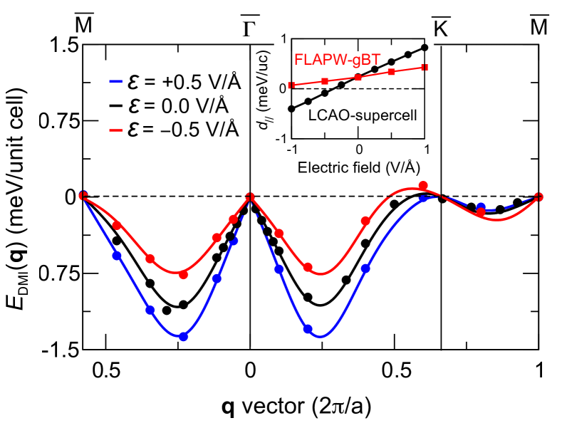
Fig. 8 shows the SOC induced DMI contributions to the energy dispersion of cycloidal spin spirals in FGT/Ge, , under electric field. When an electric field is applied, displays the same trend as in zero field, i.e., it favors cycloidal spirals with a CW rotational sense, but an electric-field induced modification in is clearly seen. The out-of-plane electric field breaks the inversion symmetry and leads to a drastic change of the nearest-neighbor DMI constant, , which increases and decreases by approximately 50% for V/Å and V/Å, respectively (see Table 2). Additionally, we find that remains almost the same.
In general, when an electric field is applied from negative to positive, the DMI favors less and less a CW rotational sense. This is also reproduced by the LCAO-supercell approach (see inset of Fig. 8) in which we even find a change of sign of the DMI constant at V/Å. However, quantitatively, we note that LCAO-supercell overestimates the DMI compared to FLAPW-gBT under an electric field. We attribute this quantitative discrepancy to the different implementations of the electric field and basis sets used in the FLAPW-gBT and LCAO-supercell methods.
Note, that the electric-field effect on the exchange interaction is opposite to that on the DMI with respect to the formation of non-collinear spin states. For , the energy dispersion without SOC (Fig. 7) rises less quickly and the exchange frustration increases which is favorable for the emergence of spin structures such as skyrmions. However, the energy contribution due to DMI (Fig. 8) shows a shallower energy minimum for and the nearest neighbor DMI constant drops accordingly (cf. Table 2). This shows that both the effect on the exchange and on the DMI needs to be taken into account in order to predict electric-field assisted formation of non-collinear spin structures in line with previous theoretical studies [65, 91]. In contrast, the electric-field effect on the magnetocrystalline anisotropy energy is small (see next section).
III.4 FGT/Ge: Magnetocrystalline anisotropy energy
We define the MAE as the difference in total energies between a configuration in which the magnetization in the ferromagnetic state is in-plane () and out-of-plane () with respect to the FGT monolayer
| (15) |
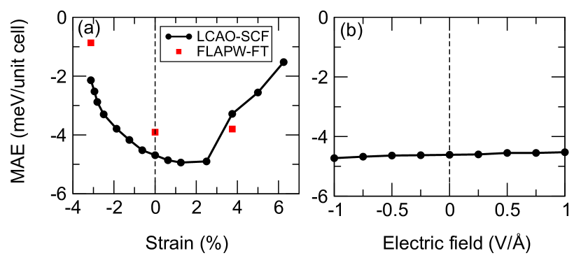
In Fig. 9, we plot the MAE in the FGT/Ge heterostructure as a function of strain and electric field. We calculate the MAE using two approaches: (i) The MAE is defined as the energy difference between self-consistently converged total energies including SOC, namely LCAO-SCF and (ii) the MAE is taken as the band energy difference (also known as force theorem) obtained after a one-step diagonalization of the full Hamiltonian including SOC, starting from the well converged self-consistent scalar relativistic (without SOC) density/potential, namely FLAPW-FT.
We find that FGT/Ge has a strong perpendicular MAE of more than 4.62 meV (about 1.5 meV/Fe). Interestingly, when a mechanical strain is applied, the MAE can be significantly reduced to 2.08 meV at and 1.44 meV at , respectively. In general, the two DFT approaches yield a good qualitative agreement concerning the change of the MAE with strain. From the local decomposition of MAE evaluated by the grand-canonical formulation [92, 93], we find that Fe1 and Fe3 favor favor out-of-plane anisotropy while the Fe2 layer favors an in-plane direction of the moments. In contrast, we find that an applied electric field has a much smaller effect on the MAE of FGT/Ge (Fig. 9(b)).
IV Conclusion
In summary, Fe3GeTe2/germanene has been investigated as a representative 2D vdW magnetic heterostructure using three current state-of-the-art approaches to map the ab initio DFT calculations to an atomistic spin model: (i) The Green’s function approach performing infinitesimal rotations, (ii) the spin spiral method employing the generalized Bloch theorem for various vectors, and (iii) the supercell approach based on the chirality-dependent total energy difference. We obtain good qualitative agreement for the Heisenberg exchange and Dzyaloshinskii-Moriya interaction in FGT/Ge using these three different approaches. We obtain almost quantitative agreement for the DMI between methods (ii) and (iii), indicating that the nearest-neighbor approximation is valid in the FGT/Ge heterostructure. Furthermore, we have studied the electronic and magnetic ground states of the FGT/Ge heterostructure under biaxial mechanical strain, stacking, and a perpendicular electric field. We have shown that the strength of the DMI can be significantly modified via strain and stacking order, tracing its origin to the geometrical change and hybridization effect. In particular, when a small compressive strain is applied, the DMI is strongly enhanced while the MAE, in contrast, is significantly decreased, which allow the possibility of nanoscale skyrmions at a low magnetic field [58]. On the other hand, an electric field changes the DMI and the exchange constants almost linearly. If we apply a large enough electric field, we also expect a change of the sign of the DMI, i.e. a reversed rotational sense of the favored non-collinear spin structures. The electric field effect on the magnetocrystalline anisotropy is small for the FGT/Ge heterostructure.
Acknowledgments
This study has been supported through the ANR Grant No. ANR-22-CE24-0019. This study has been (partially) supported through the grant NanoX no. ANR-17-EURE-0009 in the framework of the “Programme des Investissements d’Avenir”. S. Ha, T. D. and S. He. gratefully acknowledge financial support from the Deutsche Forschungsgemeinschaft (DFG, German Research Foundation) through SPP2137 “Skyrmionics” (project no. 462602351). This work was performed using HPC resources from CALMIP (Grant 2023-[P21008]). D. Li thanks F. Nickel for valuable discussions.
Appendix A: Fitted Heisenberg exchange parameters for free-standing FGT
In Table 3, we present the fitted parameters up to the seventh nearest neighbors for free-standing FGT. Note that, in the main text, we only benchmarked the NN exchange parameter.
| Fe3-Fe3 (Fe1-Fe1) | 10.42 | 0.30 | 1.28 | 0.19 | 0.28 | 0.03 | 0.04 |
| Fe2-Fe2 | 2.02 | 0.50 | 0.53 | 0.20 | 0.01 | 0.03 | 0.38 |
| Fe3-Fe2 (Fe2-Fe1) | 16.50 | 5.42 | 1.23 | 0.82 | 1.01 | 1.11 | 0.50 |
| Fe3-Fe1 | 83.47 | 6.40 | 4.13 | 6.86 | 1.08 | 1.09 | 1.25 |
Appendix B: Quenching of magnetic moment
Spin spirals can be characterized by their reciprocal spin spiral vector , which determines the propagation direction of the spiral. For a rotation axis along the direction, their magnetization is defined as
| (16) |
where is the position of site and is the cone angle. For the special value , we obtain flat spin spirals.
We show in Fig. 10 the variation of magnetic moments along vectors for (a) flat and (b) conical spin spirals for Fe2-Fe2 spin spirals in a freestanding FGT monolayer, where we rotate only the spins of the Fe2 atoms by fixing other two layers to the FM state. For flat spin spirals (Fig. 10(a)), only the Fe3 and Fe1 layers possess a magnetic moment, while the moments of the Fe2 atom vanish due to symmetry. On the other hand, we obtain the expected magnetic moments (close to the FM state) for all three atoms.
Appendix C: The PDOS in FGT/Ge without and with strain
To further show that the mechanism of strong enhancement of DMI originates mainly from the Fe1 atom related pairs (see Fig. 5), the PDOS of Fe atoms in FGT/Ge under a strain of 3% and 0% are analyzed in Fig. 11. The largest difference between the two cases originates from the Fe1 atom, which is located at the interface.
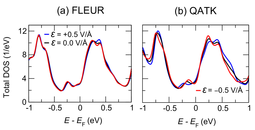
Appendix D: Comparison of FLEUR and QATK
We plot in Fig. 12 the total DOS for FGT/Ge calculated by the FLEUR code (left) and by the QATK code (right) at different electric fields. We note that the effect of the electric field on the PDOS is much more pronounced in QATK than in FLEUR, leading to the quantitative difference in the variation of the DMI with electric field observed in Fig. 8 (inset).
References
- Bogdanov and Yablonskii [1989] A. Bogdanov and D. Yablonskii, Thermodynamically stable “vortices” in magnetically ordered crystals. the mixed state of magnets, Zh. Eksp. Teor. Fiz 95, 178 (1989).
- Fert et al. [2013] A. Fert, V. Cros, and J. Sampaio, Nat. Nanotechnol. 8, 152 (2013).
- Luo et al. [2018] S. Luo, M. Song, X. Li, Y. Zhang, J. Hong, X. Yang, X. Zou, N. Xu, and L. You, Reconfigurable skyrmion logic gates, Nano Lett. 18, 1180 (2018).
- Song et al. [2020] K. Song, J. Jeong, B. Pan, X. Zhang, J. Xia, S. Cha, T. Park, K. Kim, S. Finizio, J. Raabe, et al., Skyrmion-based artificial synapses for neuromorphic computing, Nat. Electron. 3, 148 (2020).
- Psaroudaki and Panagopoulos [2021] C. Psaroudaki and C. Panagopoulos, Skyrmion qubits: A new class of quantum logic elements based on nanoscale magnetization, Phys. Rev. Lett. 127, 067201 (2021).
- Moriya [1960] T. Moriya, Anisotropic superexchange interaction and weak ferromagnetism, Phys. Rev. 120, 91 (1960).
- Dzialoshinskii [1957] I. E. Dzialoshinskii, Thermodynamic theory of “weak” ferromagnetism in antiferromagnetic substances, Sov. Phys. JETP 5, 1259 (1957).
- Fert and Levy [1980] A. Fert and P. M. Levy, Role of anisotropic exchange interactions in determining the properties of spin-glasses, Phys. Rev. Lett. 44, 1538 (1980).
- Bode et al. [2007] M. Bode, M. Heide, K. Von Bergmann, P. Ferriani, S. Heinze, G. Bihlmayer, A. Kubetzka, O. Pietzsch, S. Blügel, and R. Wiesendanger, Chiral magnetic order at surfaces driven by inversion asymmetry, Nature 447, 190 (2007).
- Mühlbauer et al. [2009] S. Mühlbauer, B. Binz, F. Jonietz, C. Pfleiderer, A. Rosch, A. Neubauer, R. Georgii, and P. Boni, Skyrmion lattice in a chiral magnet, Science 323, 915 (2009).
- Yu et al. [2010] X. Yu, Y. Onose, N. Kanazawa, J. Park, J. Han, Y. Matsui, N. Nagaosa, and Y. Tokura, Real-space observation of a two-dimensional skyrmion crystal, Nature 465, 901 (2010).
- Heinze et al. [2011] S. Heinze, K. Von Bergmann, M. Menzel, J. Brede, A. Kubetzka, R. Wiesendanger, G. Bihlmayer, and S. Blügel, Spontaneous atomic-scale magnetic skyrmion lattice in two dimensions, Nat. Phys. 7, 713 (2011).
- Romming et al. [2013] N. Romming, C. Hanneken, M. Menzel, J. Bickel, B. Wolter, K. von Bergmann, A. Kubetzka, and R. Wiesendanger, Writing and deleting single magnetic skyrmions, Science 341, 636 (2013).
- Hervé et al. [2018] M. Hervé, B. Dupé, R. Lopes, M. Böttcher, M. D. Martins, T. Balashov, L. Gerhard, J. Sinova, and W. Wulfhekel, Stabilizing spin spirals and isolated skyrmions at low magnetic field exploiting vanishing magnetic anisotropy, Nat. Commun. 9, 1015 (2018).
- Meyer et al. [2019] S. Meyer, M. Perini, S. von Malottki, A. Kubetzka, R. Wiesendanger, K. von Bergmann, and S. Heinze, Isolated zero field sub-10 nm skyrmions in ultrathin Co films, Nat. Commun. 10, 3823 (2019).
- Moreau-Luchaire et al. [2016] C. Moreau-Luchaire, C. Moutafis, N. Reyren, J. Sampaio, C. Vaz, N. Van Horne, K. Bouzehouane, K. Garcia, C. Deranlot, P. Warnicke, et al., Additive interfacial chiral interaction in multilayers for stabilization of small individual skyrmions at room temperature, Nat. Nanotechnol. 11, 444 (2016).
- Boulle et al. [2016] O. Boulle, J. Vogel, H. Yang, S. Pizzini, D. de Souza Chaves, A. Locatelli, T. Menteş, A. Sala, L. Buda-Prejbeanu, O. Klein, et al., Room-temperature chiral magnetic skyrmions in ultrathin magnetic nanostructures, Nat. Nanotechnol. 11, 449 (2016).
- Woo et al. [2016] S. Woo, K. Litzius, B. Krüger, M. Im, L. Caretta, K. Richter, M. Mann, A. Krone, R. M. Reeve, M. Weigand, et al., Observation of room-temperature magnetic skyrmions and their current-driven dynamics in ultrathin metallic ferromagnets, Nat. Mater. 15, 501 (2016).
- Soumyanarayanan et al. [2017] A. Soumyanarayanan, M. Raju, A. Gonzalez Oyarce, A. Tan, M. Im, A. Petrovic, P. Ho, K. Khoo, M. Tran, C. Gan, et al., Tunable room-temperature magnetic skyrmions in Ir/Fe/Co/Pt multilayers, Nat. Mater. 16, 898 (2017).
- Caretta et al. [2018] L. Caretta, M. Mann, F. Büttner, K. Ueda, B. Pfau, C. Günther, P. Hessing, A. Churikova, C. Klose, M. Schneider, et al., Fast current-driven domain walls and small skyrmions in a compensated ferrimagnet, Nat. Nanotechnol. 13, 1154 (2018).
- Legrand et al. [2020] W. Legrand, D. Maccariello, F. Ajejas, S. Collin, A. Vecchiola, K. Bouzehouane, N. Reyren, V. Cros, and A. Fert, Room-temperature stabilization of antiferromagnetic skyrmions in synthetic antiferromagnets, Nat. Mater. 19, 34 (2020).
- Gong et al. [2017] C. Gong, L. Li, Z. Li, H. Ji, A. Stern, Y. Xia, T. Cao, W. Bao, C. Wang, Y. Wang, et al., Discovery of intrinsic ferromagnetism in two-dimensional van der waals crystals, Nature 546, 265 (2017).
- Huang et al. [2017] B. Huang, G. Clark, E. Navarro-Moratalla, D. Klein, R. Cheng, K. Seyler, D. Zhong, E. Schmidgall, M. McGuire, D. Cobden, et al., Layer-dependent ferromagnetism in a van der waals crystal down to the monolayer limit, Nature 546, 270 (2017).
- Deng et al. [2018] Y. Deng, Y. Yu, Y. Song, J. Zhang, N. Wang, Z. Sun, Y. Yi, Y. Wu, S. Wu, J. Zhu, et al., Gate-tunable room-temperature ferromagnetism in two-dimensional Fe3GeTe2, Nature 563, 94 (2018).
- Wu et al. [2020] Y. Wu, S. Zhang, J. Zhang, W. Wang, Y. Zhu, J. Hu, G. Yin, K. Wong, C. Fang, C. Wan, et al., Néel-type skyrmion in WTe2/Fe3GeTe2 van der waals heterostructure, Nat. Commun. 11, 3860 (2020).
- Yang et al. [2020] M. Yang, Q. Li, R. Chopdekar, R. Dhall, J. Turner, J. Carlström, C. Ophus, C. Klewe, P. Shafer, A. N’Diaye, et al., Creation of skyrmions in van der waals ferromagnet Fe3GeTe2 on (Co/Pd)n superlattice, Sci. Adv. 6, eabb5157 (2020).
- Wu et al. [2022] Y. Wu, B. Francisco, Z. Chen, W. Wang, Y. Zhang, C. Wan, X. Han, H. Chi, Y. Hou, A. Lodesani, G. Yin, K. Liu, Y. Cui, K. Wang, and J. Moodera, A van der waals interface hosting two groups of magnetic skyrmions, Adv. Mater. 34, 2110583 (2022).
- Yang et al. [2022] H.-H. Yang, N. Bansal, P. Rüßmann, M. Hoffmann, L. Zhang, D. Go, Q. Li, A.-A. Haghighirad, K. Sen, S. Blügel, M. L. Tacon, Y. Mokrousov, and W. Wulfhekel, Magnetic domain walls of the van der waals material Fe3GeTe2, 2D Materials 9, 025022 (2022).
- Costa et al. [2020] M. Costa, N. M. R. Peres, J. Fernández-Rossier, and A. T. Costa, Nonreciprocal magnons in a two-dimensional crystal with out-of-plane magnetization, Phys. Rev. B 102, 014450 (2020).
- Liang et al. [2020] J. Liang, W. Wang, H. Du, A. Hallal, K. Garcia, M. Chshiev, A. Fert, and H. Yang, Very large Dzyaloshinskii-Moriya interaction in two-dimensional janus manganese dichalcogenides and its application to realize skyrmion states, Phys. Rev. B 101, 184401 (2020).
- Yuan et al. [2020] J. Yuan, Y. Yang, Y. Cai, Y. Wu, Y. Chen, X. Yan, and L. Shen, Intrinsic skyrmions in monolayer janus magnets, Phys. Rev. B 101, 094420 (2020).
- Xu et al. [2020] C. Xu, J. Feng, S. Prokhorenko, Y. Nahas, H. Xiang, and L. Bellaiche, Topological spin texture in janus monolayers of the chromium trihalides Cr(I, , Phys. Rev. B 101, 060404(R) (2020).
- Cui et al. [2020] Q. Cui, J. Liang, Z. Shao, P. Cui, and H. Yang, Strain-tunable ferromagnetism and chiral spin textures in two-dimensional janus chromium dichalcogenides, Phys. Rev. B 102, 094425 (2020).
- Jiang et al. [2021a] J. Jiang, X. Liu, R. Li, and W. Mi, Topological spin textures in a two-dimensional MnBi2(Se, Te)4 janus material, Appl. Phys. Lett. 119, 072401 (2021a).
- Shen et al. [2022] Z. Shen, C. Song, Y. Xue, Z. Wu, J. Wang, and Z. Zhong, Strain-tunable dzyaloshinskii-moriya interaction and skyrmions in two-dimensional janus ( = Cl, Br, I, ) trihalide monolayers, Phys. Rev. B 106, 094403 (2022).
- Park et al. [2021] T. Park, L. Peng, J. Liang, A. Hallal, F. S. Yasin, X. Zhang, K. M. Song, S. J. Kim, K. Kim, M. Weigand, G. Schütz, S. Finizio, J. Raabe, K. Garcia, J. Xia, Y. Zhou, M. Ezawa, X. Liu, J. Chang, H. C. Koo, Y. D. Kim, M. Chshiev, A. Fert, H. Yang, X. Yu, and S. Woo, Néel-type skyrmions and their current-induced motion in van der waals ferromagnet-based heterostructures, Phys. Rev. B 103, 104410 (2021).
- Sun et al. [2020] W. Sun, W. Wang, H. Li, G. Zhang, D. Chen, J. Wang, and Z. Cheng, Controlling bimerons as skyrmion analogues by ferroelectric polarization in 2D van der waals multiferroic heterostructures, Nat. Commun. 11, 5930 (2020).
- Tong et al. [2018] Q. Tong, F. Liu, J. Xiao, and W. Yao, Nano Lett. 18, 7194 (2018).
- Amoroso et al. [2020] D. Amoroso, P. Barone, and S. Picozzi, Spontaneous skyrmionic lattice from anisotropic symmetric exchange in a Ni-halide monolayer, Nat. Commun. 11, 1 (2020).
- Gong and Zhang [2019] C. Gong and X. Zhang, Two-dimensional magnetic crystals and emergent heterostructure devices, Science 363, eaav4450 (2019).
- Jiang et al. [2021b] X. Jiang, Q. Liu, J. Xing, N. Liu, Y. Guo, Z. Liu, and J. Zhao, Recent progress on 2D magnets: Fundamental mechanism, structural design and modification, Appl. Phys. Rev. 8, 031305 (2021b).
- Ferriani et al. [2008] P. Ferriani, K. von Bergmann, E. Y. Vedmedenko, S. Heinze, M. Bode, M. Heide, G. Bihlmayer, S. Blügel, and R. Wiesendanger, Atomic-scale spin spiral with a unique rotational sense: Mn monolayer on W (001), Phys. Rev. Lett. 101, 027201 (2008).
- Heide et al. [2009] M. Heide, G. Bihlmayer, and S. Blügel, Describing Dzyaloshinskii-Moriya spirals from first principles, Phys. B 404, 2678 (2009).
- Yanes et al. [2013] R. Yanes, J. Jackson, L. Udvardi, L. Szunyogh, and U. Nowak, Exchange bias driven by Dzyaloshinskii-Moriya interactions, Phys. Rev. Lett. 111, 217202 (2013).
- Kashid et al. [2014] V. Kashid, T. Schena, B. Zimmermann, Y. Mokrousov, S. Blügel, V. Shah, and H. G. Salunke, Dzyaloshinskii-moriya interaction and chiral magnetism in zigzag chains: Tight-binding model and ab initio calculations, Phys. Rev. B 90, 054412 (2014).
- Zimmermann et al. [2014] B. Zimmermann, M. Heide, G. Bihlmayer, and S. Blügel, First-principles analysis of a homochiral cycloidal magnetic structure in a monolayer Cr on W(110), Phys. Rev. B 90, 115427 (2014).
- Dupé et al. [2014] B. Dupé, M. Hoffmann, C. Paillard, and S. Heinze, Tailoring magnetic skyrmions in ultra-thin transition metal films, Nat. Commun. 5, 4030 (2014).
- Simon et al. [2014] E. Simon, K. Palotás, L. Rózsa, L. Udvardi, and L. Szunyogh, Formation of magnetic skyrmions with tunable properties in PdFe bilayer deposited on Ir(111), Phys. Rev. B 90, 094410 (2014).
- Yang et al. [2015a] H. Yang, A. Thiaville, S. Rohart, A. Fert, and M. Chshiev, Anatomy of Dzyaloshinskii-Moriya interaction at interfaces, Phys. Rev. Lett. 115, 267210 (2015a).
- Vida et al. [2016] G. J. Vida, E. Simon, L. Rózsa, K. Palotás, and L. Szunyogh, Domain-wall profiles in /Pt(111) ultrathin films: Influence of the Dzyaloshinskii-Moriya interaction, Phys. Rev. B 94, 214422 (2016).
- Yamamoto et al. [2017] K. Yamamoto, A. Pradipto, K. Nawa, T. Akiyama, T. Ito, T. Ono, and K. Nakamura, Interfacial Dzyaloshinskii-Moriya interaction and orbital magnetic moments of metallic multilayer films, AIP Advances 7, 056302 (2017).
- Simon et al. [2018] E. Simon, L. Rózsa, K. Palotás, and L. Szunyogh, Magnetism of a Co monolayer on Pt(111) capped by overlayers of elements: A spin-model study, Phys. Rev. B 97, 134405 (2018).
- Jadaun et al. [2020] P. Jadaun, L. Register, and S. Banerjee, The microscopic origin of DMI in magnetic bilayers and prediction of giant DMI in new bilayers, npj Comput Mater 6, 88 (2020).
- Zimmermann et al. [2019] B. Zimmermann, G. Bihlmayer, M. Böttcher, M. Bouhassoune, S. Lounis, J. Sinova, S. Heinze, S. Blügel, and B. Dupé, Comparison of first-principles methods to extract magnetic parameters in ultrathin films: Co/Pt(111), Phys. Rev. B 99, 214426 (2019).
- Liechtenstein et al. [1987] A. Liechtenstein, M. Katsnelson, V. Antropov, and V. Gubanov, Local spin density functional approach to the theory of exchange interactions in ferromagnetic metals and alloys, J. Magn. Magn. Mater. 67, 65 (1987).
- Sandratskii [1986] L. M. Sandratskii, Energy band structure calculations for crystals with spiral magnetic structure, Phys. Status Solidi B 136, 167 (1986).
- Kurz et al. [2004] P. Kurz, F. Förster, L. Nordström, G. Bihlmayer, and S. Blügel, Ab initio treatment of noncollinear magnets with the full-potential linearized augmented plane wave method, Phys. Rev. B 69, 024415 (2004).
- Li et al. [2022] D. Li, S. Haldar, and S. Heinze, Strain-driven zero-field near-10 nm skyrmions in two-dimensional van der waals heterostructures, Nano Lett. 22, 7706 (2022).
- Szilva et al. [2013] A. Szilva, M. Costa, A. Bergman, L. Szunyogh, L. Nordström, and O. Eriksson, Interatomic exchange interactions for finite-temperature magnetism and nonequilibrium spin dynamics, Phys. Rev. Lett. 111, 127204 (2013).
- Smidstrup et al. [2019] S. Smidstrup, T. Markussen, P. Vancraeyveld, J. Wellendorff, J. Schneider, T. Gunst, B. Verstichel, D. Stradi, P. Khomyakov, U. Vej-Hansen, et al., QuantumATK: an integrated platform of electronic and atomic-scale modelling tools, J. Phys. Condens. Matter 32, 015901 (2019).
- [61] www.flapw.de.
- Xiang et al. [2013] H. Xiang, C. Lee, H.-J. Koo, X. Gong, and M.-H. Whangbo, Magnetic properties and energy-mapping analysis, Dalton Transactions 42, 823 (2013).
- Yu et al. [2022] H. Yu, C. Xu, X. Li, F. Lou, L. Bellaiche, Z. Hu, X. Gong, and H. Xiang, Complex spin hamiltonian represented by an artificial neural network, Phys. Rev. B 105, 174422 (2022).
- Oroszlány et al. [2019] L. Oroszlány, J. Ferrer, A. Deák, L. Udvardi, and L. Szunyogh, Exchange interactions from a nonorthogonal basis set: From bulk ferromagnets to the magnetism in low-dimensional graphene systems, Phys. Rev. B 99, 224412 (2019).
- Paul and Heinze [2022] S. Paul and S. Heinze, Electric-field driven stability control of skyrmions in an ultrathin transition-metal film, Npj Comput. Mater. 8, 1 (2022).
- Du et al. [2022] W. Du, K. Dou, Z. He, Y. Dai, B. Huang, and Y. Ma, Spontaneous magnetic skyrmions in single-layer CrInX3 (X= Te, Se), Nano Lett. 22, 3440 (2022).
- Lopes et al. [2021] J. M. J. Lopes, D. Czubak, E. Zallo, A. I. Figueroa, C. Guillemard, M. Valvidares, J. Rubio-Zuazo, J. López-Sanchéz, S. O. Valenzuela, M. Hanke, and M. Ramsteiner, Large-area van der waals epitaxy and magnetic characterization of Fe3GeTe2 films on graphene, 2D Materials 8, 041001 (2021).
- Wang et al. [2018] Z. Wang, D. Sapkota, T. Taniguchi, K. Watanabe, D. Mandrus, and A. F. Morpurgo, Tunneling spin valves based on Fe3GeTe2/hBN/Fe3GeTe2 van der waals heterostructures, Nano Lett. 18, 4303 (2018).
- Deiseroth et al. [2006] H. Deiseroth, K. Aleksandrov, C. Reiner, L. Kienle, and R. Kremer, Fe3GeTe2 and Ni3GeTe2 – two new layered transition-metal compounds: Crystal structures, hrtem investigations, and magnetic and electrical properties, Eur. J. Inorg. Chem. 2006, 1561 (2006).
- Chen et al. [2013] B. Chen, J. Yang, H. Wang, M. Imai, H. Ohta, C. Michioka, K. Yoshimura, and M. Fang, Magnetic properties of layered itinerant electron ferromagnet Fe3GeTe2, J. Phys. Soc. Jpn. 82, 124711 (2013).
- Grimme et al. [2010] S. Grimme, J. Antony, S. Ehrlich, and H. Krieg, A consistent and accurate ab initio parametrization of density functional dispersion correction (DFT-D) for the 94 elements H-Pu, J. Chem. Phys. 132, 154104 (2010).
- Zhuang et al. [2016] H. Zhuang, P. Kent, and R. Hennig, Strong anisotropy and magnetostriction in the two-dimensional stoner ferromagnet Fe3GeTe2, Phys. Rev. B 93, 134407 (2016).
- Ghosh et al. [2022] S. Ghosh, S. Ershadrad, V. Borisov, and B. Sanyal, Unraveling effects of electron correlation in two-dimensional FenGeTe2 () by dynamical mean field theory, arXiv preprint arXiv:2212.08552 (2022).
- He et al. [2021a] J. He, S. Li, A. Bandyopadhyay, and T. Frauenheim, Unravelling photoinduced interlayer spin transfer dynamics in two-dimensional nonmagnetic-ferromagnetic van der waals heterostructures, Nano Lett. 21, 3237 (2021a).
- Leonov and Mostovoy [2015] A. Leonov and M. Mostovoy, Multiply periodic states and isolated skyrmions in an anisotropic frustrated magnet, Nat. Commun. 6, 8275 (2015).
- von Malottki et al. [2017] S. von Malottki, B. Dupé, P. Bessarab, A. Delin, and S. Heinze, Enhanced skyrmion stability due to exchange frustration, Sci. Rep. 7, 1 (2017).
- Zhang et al. [2020] Y. Zhang, C. Xu, P. Chen, Y. Nahas, S. Prokhorenko, and L. Bellaiche, Emergence of skyrmionium in a two-dimensional janus monolayer, Phys. Rev. B 102, 241107(R) (2020).
- Rijal et al. [2021] S. Rijal, C. Xu, and L. Bellaiche, Designing frustration in two-dimensional magnetic systems via the application of uniaxial strain, Phys. Rev. B 103, 014442 (2021).
- Zhu et al. [2021] M. Zhu, Y. You, G. Xu, J. Tang, Y. Gong, and F. Xu, Strain modulation of magnetic coupling in the metallic van der waals magnet Fe3GeTe2, Intermetallics 131, 107085 (2021).
- Xu et al. [2022] C. Xu, X. Li, P. Chen, Y. Zhang, H. Xiang, and L. Bellaiche, Assembling diverse skyrmionic phases in Fe3GeTe2 monolayer, Adv. Mater. , 2107779 (2022).
- Paul et al. [2020] S. Paul, S. Haldar, S. von Malottki, and S. Heinze, Role of higher-order exchange interactions for skyrmion stability, Nat. Commun. 11, 4756 (2020).
- Shen et al. [2021] Z. Shen, X. Bo, K. Cao, X. Wan, and L. He, Magnetic ground state and electron-doping tuning of curie temperature in Fe3GeTe2: First-principles studies, Phys. Rev. B 103, 085102 (2021).
- Laref et al. [2020] S. Laref, K. Kim, and A. Manchon, Elusive Dzyaloshinskii-Moriya interaction in monolayer Fe3GeTe2, Phys. Rev. B 102, 060402(R) (2020).
- Yang et al. [2015b] H. Yang, A. Thiaville, S. Rohart, A. Fert, and M. Chshiev, Anatomy of Dzyaloshinskii-Moriya interaction at interfaces, Phys. Rev. Lett. 115, 267210 (2015b).
- Hu et al. [2020] X. Hu, Y. Zhao, X. Shen, A. Krasheninnikov, Z. Chen, and L. Sun, Enhanced ferromagnetism and tunable magnetism in Fe3GeTe2 monolayer by strain engineering, ACS Appl. Mater. Interfaces 12, 26367 (2020).
- Huang et al. [2022] K. Huang, D. Shao, and E. Tsymbal, Ferroelectric control of magnetic skyrmions in two-dimensional van der waals heterostructures, Nano Lett. 22, 3349 (2022).
- He et al. [2021b] X. He, N. Helbig, M. Verstraete, and E. Bousquet, TB2J: A python package for computing magnetic interaction parameters, Comput. Phys. Commun. 264, 107938 (2021b).
- Weinert et al. [2009] M. Weinert, G. Schneider, R. Podloucky, and J. Redinger, FLAPW: applications and implementations, J. Phys.: Condens. Matter 21, 084201 (2009).
- Oba et al. [2015] M. Oba, K. Nakamura, T. Akiyama, T. Ito, M. Weinert, and A. J. Freeman, Electric-field-induced modification of the magnon energy, exchange interaction, and Curie temperature of transition-metal thin films, Phys. Rev. Lett. 114, 107202 (2015).
- Hsu et al. [2017] P. Hsu, A. Kubetzka, A. Finco, N. Romming, K. Von Bergmann, and R. Wiesendanger, Electric-field-driven switching of individual magnetic skyrmions, Nat. Nanotechnol. 12, 123 (2017).
- Goerzen et al. [2022] M. A. Goerzen, S. von Malottki, G. J. Kwiatkowski, P. F. Bessarab, and S. Heinze, Atomistic spin simulations of electric-field-assisted nucleation and annihilation of magnetic skyrmions in Pd/Fe/Ir(111), Phys. Rev. B 105, 214435 (2022).
- Li et al. [2013] D. Li, A. Smogunov, C. Barreteau, F. Ducastelle, and D. Spanjaard, Magnetocrystalline anisotropy energy of and slabs and nanoclusters: A detailed local analysis within a tight-binding model, Phys. Rev. B 88, 214413 (2013).
- Li et al. [2014] D. Li, C. Barreteau, M. R. Castell, F. Silly, and A. Smogunov, Out- versus in-plane magnetic anisotropy of free Fe and Co nanocrystals: Tight-binding and first-principles studies, Phys. Rev. B 90, 205409 (2014).