Original Article \paperfieldJournal Section \contribCunxi Dai, Xiaohan Liu and Jianxiang Zhou contributed equally to this work. \corraddressZhenzhong Jia, Department of Mechanical and Energy Engineering, Southern University of Science and Technology, 518000 Shenzhen, China. \corremailjiazz@sustech.edu.cn \fundinginfoScience, Technology and Innovation Commission of Shenzhen Municipality, Grant/Award Number: ZDSYS20200811143601004
SWheg: A Wheel-Leg Transformable Robot With Minimalist Actuator Realization
Abstract
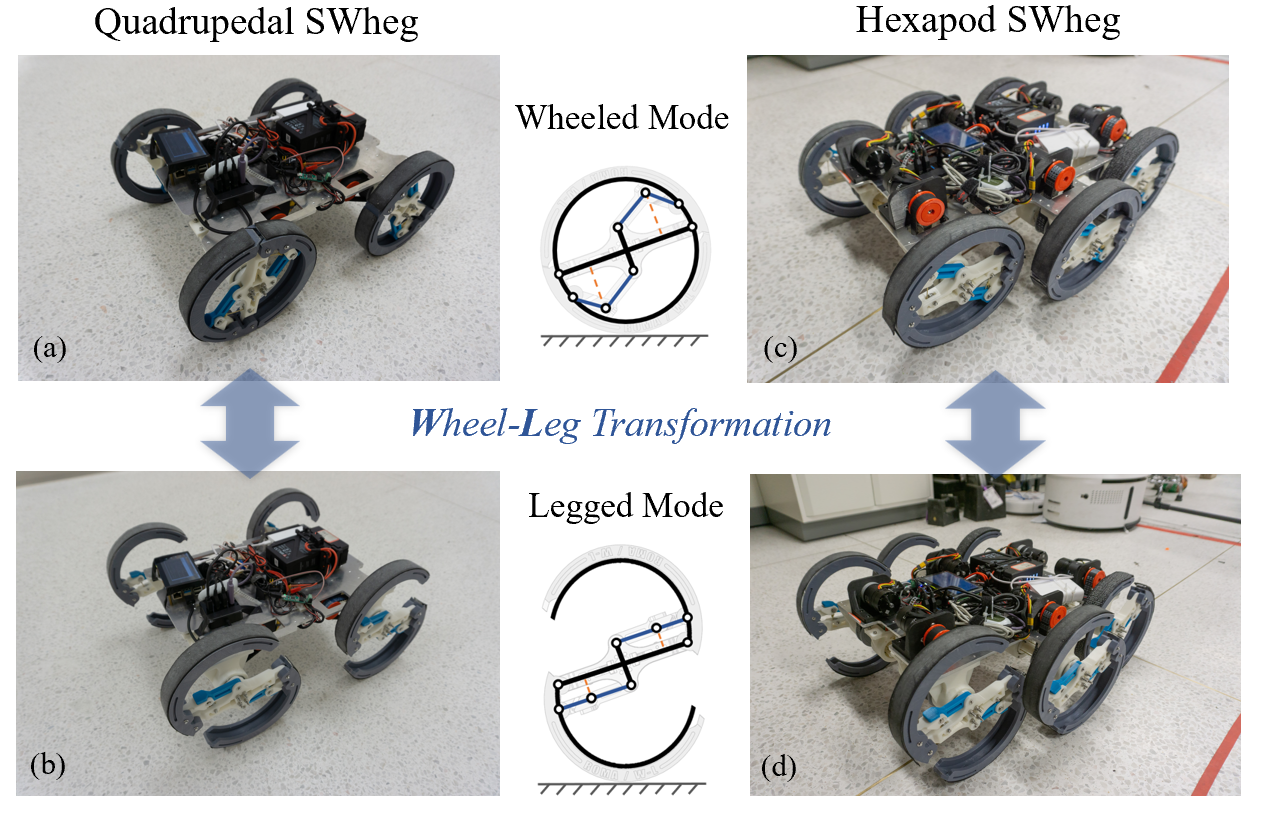
This article presents the design, implementation, and performance evaluation of SWheg, a novel modular wheel-leg transformable robot family with minimalist actuator realization. SWheg takes advantage of both wheeled and legged locomotion by seamlessly integrating them on a single platform. In contrast to other designs that use multiple actuators, SWheg uses only one actuator to drive the transformation of all the wheel-leg modules in sync. This means an -legged SWheg robot requires only actuators, which can significantly reduce the cost and malfunction rate of the platform. The tendon-driven wheel-leg transformation mechanism based on a four-bar linkage can perform fast morphology transitions between wheels and legs. We validated the design principle with two SWheg robots with four and six wheel-leg modules separately, namely Quadrupedal SWheg and Hexapod SWheg. The design process, mechatronics infrastructure, and the gait behavioral development of both platforms were discussed. The performance of the robot was evaluated in various scenarios, including driving and turning in wheeled mode, step crossing, irregular terrain passing, and stair climbing in legged mode. The comparison between these two platforms was also discussed.
keywords:
Wheel-Leg Mechanism, Quadruped, Hexapod, Transformable Robot, Four-Bar Linkage, Tendon-Driven1 Introduction
Wheels and legs mobile robots are still the most popular form of ground locomotion platforms to negotiate two main terrain categories, namely flat and rough terrains [8]. Generally, wheeled systems feature fast, smooth and power-efficient locomotion on flat terrain, but behave poorly on rough terrain, resulting in slippage or even immobility [12]. In contrast, legged robots excel at negotiating with rough terrain but can hardly compete with wheeled robots in terms of speed and efficiency on flat ground [4]. Therefore, a hybrid wheel-leg transformable robot that enjoys the advantages of wheels on flat ground and employs the mobility of legs on rough terrain will likely have the best overall performance in various environmental conditions [7, 28].
Wheel-leg hybrid mobile platforms can be classified into three categories (details are given in the sequel) based on the hybrid strategy adopted, namely heteromorphic wheel robots, wheel-leg coexisting robots, and wheel-leg transformable robots.
Heteromorphic wheel mechanism usually features specialized fixed-shape wheels. For example, Loper has four -spoke rimless wheels that perform well on both flat ground and stairs [2, Marques2006RAPOSA]. RHex and ION utilize six compliant half-circle "C-shapes" wheels, which are also referred to as wheeled-legged (WHEG) mechanism, to overcome obstacles. Benefited from its curved shape and compliant spoke [25, 1], it behaves reliably with only open-loop control with lesser torque required compared to a straight stiff leg [15].
Another type of robot has a separate wheel and leg mechanism coexisting on the platform, and the locomotion is generated by the collaboration of these two mechanisms. For instance, Chariot III has two big wheels and four -DOF legs [22]. PEOPLER-II has two bars mounted on each of the four wheels, and locomotion can be switched between leg type and wheel type [13].Wheeleg has two pneumatically actuated -DOF front legs and two independently driven rear wheels [14].
Different from the above robots, wheel-leg transformable robots feature transforming mechanisms that alter the morphology between wheels and legs. Some platforms utilize a passive -DOF mechanism that only transforms when encountering with a vertical plane of the obstacle, such as wheel transformer, land devil ray, and shape-morphing wheel [11, 2, 24]. Some platforms use an active -DoF mechanism, and one of them uses origami to transform its wheel [15]. A robotic wheel overcomes an obstacle by pushing the spoke that forms a circular wheel [21]. FUHAR opens its spoke, which is referred to as a finger, when it climbs stairs [19]. The -DOF mechanism can only be used to overcome a small range of obstacle sizes. Therefore, to overcome this limitation, -DOF mechanisms are have been investigated. The Quattroped and STEP are examples of platforms using the -DOF mechanism [5, 10]. The Quattroped changes its wheel into the WHEG mechanism and move the wheel up and down. This transformation is used to set a strategy to climb obstacles.
Many of the wheel-leg hybrid robots mentioned above select "search and rescue" as their main tasks, such as [3, 20]. These working environments often have diverse terrains, requiring robots to have high-speed mobility over different types of terrains in order to complete the tasks in a timely manner because of the urgent nature of these tasks. Hence, wheel-leg transformable robots that can switch to suitable motion modes (i.e., wheeled mode on flat ground, legged mode in rough terrain) can be very competitive in such tasks [29]. However, the great overall performance of the wheel-leg transformable robot comes with a price, i.e., system complexity. They often feature more complicated mechatronics systems compared to robots with a single locomotion modality. Most importantly, the extra DoFs in the transformation mechanism calls for more actuators, which increases the systems’ cost and uncertainty dramatically. For example, the hexapod Slegs robot reported in [27] has at least actuators, i.e., actuators for each wheel-leg module. Slegs robot uses main actuators to drive the wheel-leg modules and additional actuators (servos or linear actuators) to switch between the wheeled and legged modes. The Quattroped robot in [5] and the turboquad robot in [8] are both quadrupedal robots with at least actuators. The turboquad robot uses main actuators to drive the specially-designed wheel-leg module, which can complete mode switching online. It also uses an additional actuator to control the Ackermann steering mechanism. Hence, it has actuators in total. To our best knowledge, all wheel-leg transformable robots reported in the literature with wheel-leg modules will have at least actuators. However, the independent transformation control of each wheel-leg module is not a key function to the robot, Theoretically, one additional actuator is sufficient to actuate the transformation of all the wheel-leg modules.
In this paper, we proposed a tendon-driven wheel-leg transformable robot design with minimal actuator realization, as shown in Figure 1. In particular, for a robot with wheel-leg modules, we only need actuators. This is only about of other literature designs. This will help reduce the system complexity, cost, failure rate, and the transformation of all the modules are synchronized by root.
The main contributions are:
-
1.
We proposed the design principle of a tendon-driven wheel-leg transformable robot with minimal actuator realization. In particular, the -legged robot only needs actuators, with only one actuator for transformation. This can greatly reduce the system’s complicity and cost.
-
2.
We designed a novel wheel-leg transformable module that used a tendon-driven mechanism for locomotion mode switching. We also proposed a design that can use a single actuator to control all tendons to finish mode switching of the entire robot.
-
3.
We proposed the design and performance evaluation of a new S-shape leg morphology and built two robot platforms to validate our design, quadrupedal SWheg, and hexapod SWheg. We also developed control algorithms for the two platforms and validated the effectiveness in both simulation and field experiments.
The remainder of this paper is organized as follows. Section 2 presents the design of the transformable wheel mechanism and the -bar linkage mechanism to create the transformation. Section 3 presents the tendon network and the mechatronics infrastructure of the platform. In Section 4, the design and performance of the modular wheel are validated. We also performed comparative power experiments on quadrupedal and hexapod robots. The results are discussed in Section 5.
2 Transformable Wheel Mechanism
In Legged robots, the geometrical configuration of the leg strongly affect the legged motion agility and energy performance [7]. Among these robots, "C-shape legs" or "half-circle legs" with curved shape and compliant spoke were a popular design choice [25, 1, 7]. This leg geometry has been proved to behave reliably with only open-loop control compared to a straight stiff leg [15]. "S-shaped legs" have two half-circle rims on a single leg, and has been previously studied in wheel-leg transformable robots such as TurboQuad and SLegs. It features similar curvature and compliant area as "C-shaped legs", and has also been proved to generate smooth legged locomotion. Moreover, ”S-shaped legs“ are more geometrically friendly to design a wheel-leg transformation mechanism, because it has two half-rims instead of a single half-rim in "C-shape legs" or "half-circle legs". Therefore, we decide to use a ”S-shaped legs“ to be the legged geometry for SWhegs [8, 27].
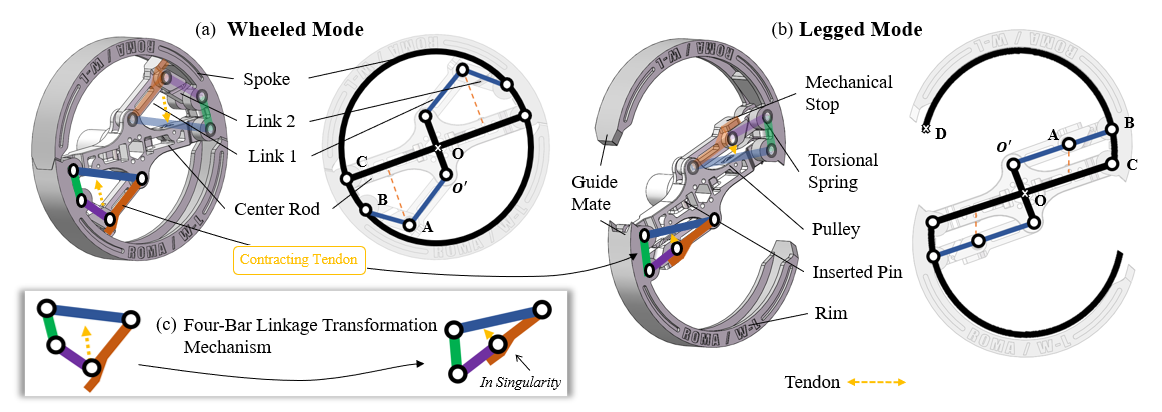
One of the key challenges to the wheel-leg transformation mechanism is to sustain legged mode without over-demanding the central servo or consuming too much power. Both of these tasks can be solved if the mechanism reaches singularity in legged mode. Towards this goal, the transformation mechanism was designed based on a four-bar parallel mechanism that reaches singularity in legged mode, so that minimum force is required from the center servo. Two four-bar linkage mechanism was placed on a single wheel-leg transformation module as marked on Figure 2. Another benefit of this configuration in legged is that the spoke is supported at two points with a stable triangle structure formed by the transformation mechanism in singularity.
The wheel-leg transformation mechanism contains two identical four-bar parallel mechanism, each support one spoke to expand from the center rod. When fully expanded, the two spokes form a "S-shape" wheel that is compliant in most area. An additional mechanical stop is designed to ensure that the mechanism reaches singularity when fully expanded. The schematic diagram of the transformation mechanism is shown in Figure 2. To optimize the transformation mechanism design, the following kinematic and requirements and goals should be set. The geometric model of the wheel is set up using MATLAB, and the values of four-bar mechanism design variables are searched by trial and error to satisfy the previous kinematic requirements. The workspace and the singularity of the transformation mechanism is shown in Figure 2.
2.1 Mechanical Design of the Modular Wheel
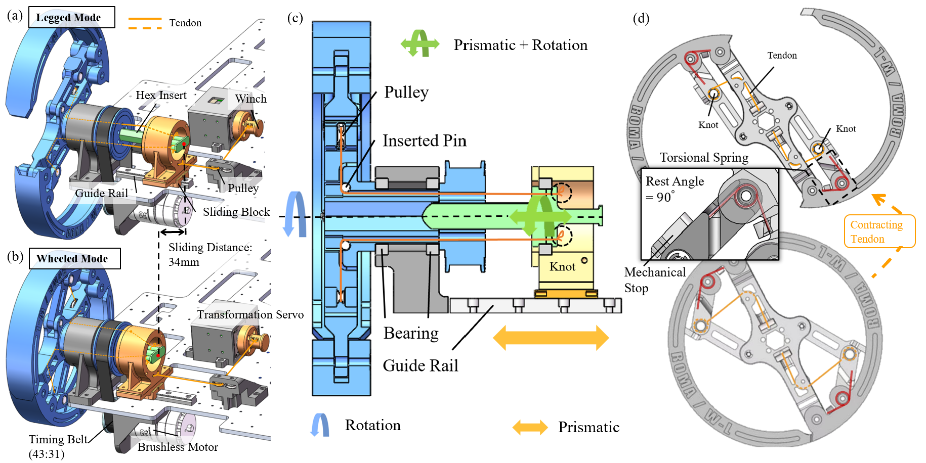
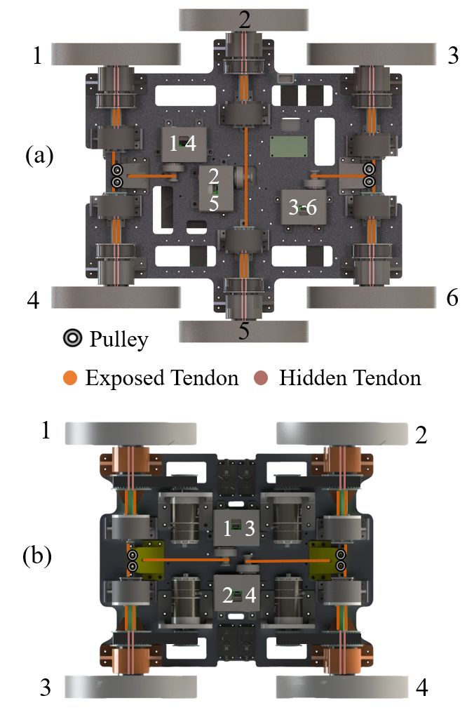
The wheel-leg transformable module is mechanically self-contained except for the transformation driving tendon, which is driven by central servo. The tendon arrangement is marked on the bottom view of the quadrupedal and hexapod platform in Figure 2. Since the tendon can only exert force in a single direction, restoring from legged mode to wheeled mode requires an additional source of force or torque. We experimented with multiple restoring methods, such as rubber bands and linear springs. The common problem with these linear elastic elements is that it does not provide powerful enough force to maintain wheeled mode. So we decided to use a torsional spring to provide restoring torque on the joint directly.
The torsional spring is embedded concentrically with joint to provide the torque to restore from wheeled mode to legged mode. The trade-off on selecting the spring stiffness is that: if the spring is too soft, it cannot maintain wheeled mode. If the spring is too stiff, the central servo will exert extra unnecessary torque to drive the transformation mechanism. So we tested with various stiffness and landed on a spring with spring constant , which is the minimum stiffness that can maintain the wheeled mode. The stiffness is determined When transforming from wheeled mode into legged mode, the central servo rotates the winch and pulls the tendon to drive the transformation mechanism on each wheel-leg module. A mechanical stop is added to link so the transformation mechanism does not cross singularity. When restoring from legged mode to wheeled mode, the central servo rotates reversely and release the tension on the tendon, the torsional spring provides the required torque to restore to wheeled mode.
An inevitable problem with the tendon driven actuation method is that the tendon rotates with the wheel while the driving servo is fixed. This would result in entangled tendon and must be solved. The most direct way to approach this problem is to separate the rotation and prismatic motion. To realize this concept, we designed a -DoF connector in series with the tendon. The connector has one rotational DoF, one linear DoF and is connected in series between the central servo and the wheel-leg module, concentric with the wheel. The prismatic range of motion is limited by guide rail length and a mechanical stop. The details of this mechanism is shown in Figure 2. The tendon from the servo winch pulls on the stator and pulls the connector slides on the guide rail, the rotor rotates passively with the wheel via the hex rod insert into the wheel-leg module. There is only one motor in each module to drive the wheel, a belt transmission system comprising two pulleys and a timing belt with a speed reduction is used.
2.2 Design Considerations Based on Quasi-Statics
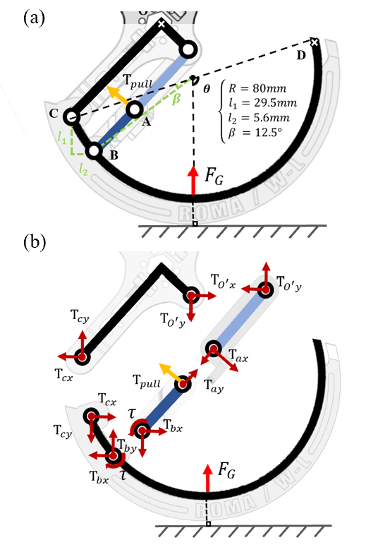
It is important to calculate the torques required for the mobile central servo with transformable wheels to design. Without loss of generality, it is assumed that the weight of the platform is and each wheel supports a load of . Also, it is supposed to move at a sufficiently low speed so that no slip occurs. The free body diagrams (FBDs) of transformable wheel are shown in Figure 2a. In singularity configuration, linkage and the tendon only have to counter with the restoring torque provided by the inserted torsional spring, the following relations can be derived:
| (1) |
Therefore, the required torque on the servo to sustain legged mode is a constant of , directly related to the spring constant and irrelevant of the direction and amplitude of , the ground reaction force.
-
1.
The mechanism forms a circle with radius when closed.
-
2.
The wheel-leg module has the largest compliant area in the legged mode.
-
3.
The mechanism should expand as much as possible, meaning to optimize the distance between joint and when fully expanded
-
4.
The four-link mechanism reaches singularity when fully expanded.
-
5.
Interference between the components during deformation must be avoided.
3 Robot Platform Design
To validate the ubiquitous feasibility of this minimal actuator realization design, and to investigate the influence of leg number on a robot’s performance, we built two mobile experiment platforms with four and six wheel-leg transformation modules, namely quadrupedal SWheg and hexapod SWheg as shown in Figure 1. We used two servos on the quadrupedal SWheg to drive the transformation mechanism of the front wheels and back wheels separately, and correspondingly three servos on the hexapod SWheg. Doing so enables the robots to transform each pair of wheels individually thus making it easier to investigate the performance of a quasi wheel-leg robot. However, it has been proved in Section 2 that it is feasible to use only one servo to drive the overall transformation.
3.1 Tendon Network Design
The tendon network on the robot platform is constructed in a way that allows a single actuator to control all tendons for mode switching of the entire robot. The transformation servo group is placed in the geometrical center of orthographic projection of the platform. Pulleys are placed to ensure the tendon pulls on the wheel-leg transformation module vertically. The transformation tendon is knotted at joint This ensures that the tendon is contained in the envelope of the wheel in both wheeled and legged mode, and is therefore not exposed to unexpected environment and risk of being cut. The tendon goes through the center rod and connects with the connector mechanism. Pins and pulleys were embedded in the transmission route to reduce transmission friction on the rod.
3.2 Mechatronics Infrastructure
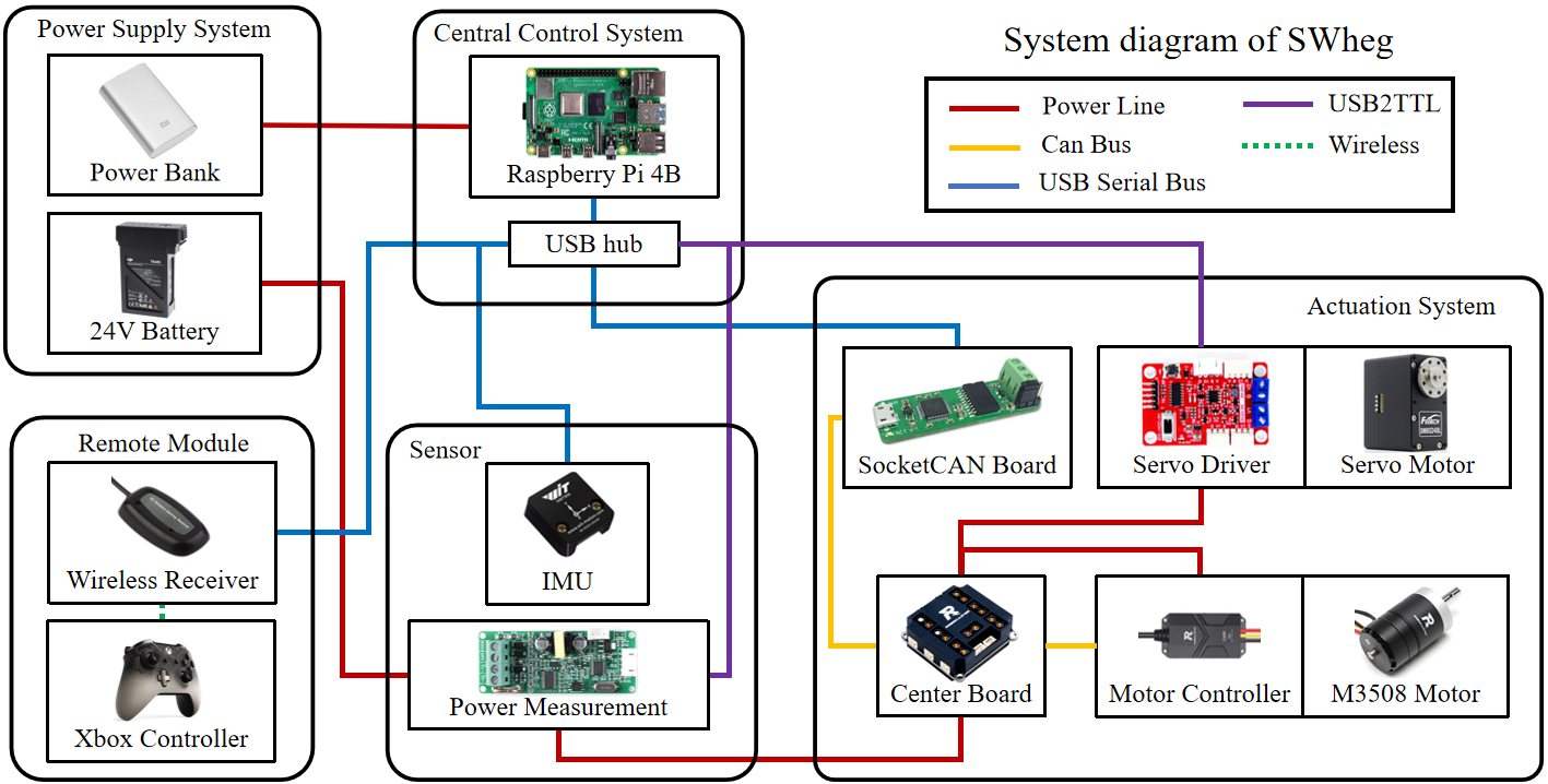
As shown in Figure 6, the main computation power on this robot is the Raspberry Pi 4B embedded computer, and Robot Operating System (ROS) is used on this board for inter-module communication. And we use the Xbox controller as a remote control module. The IMU and power measurement sensor are installed on the chassis for measuring motion smoothness and power consumption. About the actuator system, take the quadrupedal SWheg for an example, DJI M3508 brushless geared motors are used as the major power unit for this robot. Each motor is connected to a DJI C620 FOC controller. The controllers accept the current command and provide current, speed, and position feedback. A socketcan board that converts the CAN signal to the USB signal is used to connect the FOCs and the embedded computer. Two Feetech SMS serial servos are used to power the tendon-driven system. The servos are connected to a servo driver board which provides power and signal exchange. The servo driver board is also connected to the embedded computer. The specifications of the robots are summarized in Table 1.
| Quadrupedal SWheg | Hexapod SWheg | ||
| Length | Body | 0.4m | 0.47m |
| Hip-to-hip | 0.3m | 0.2m | |
| Width | Body | 0.3m | 0.3m |
| Leg-to-leg | 0.39m | 0.46m | |
| Height | Body | 0.154m | 0.154m |
| Ground to hip (legged mode) | 0.0965m | 0.0965m | |
| Ground clearance (legged mode) | 0.193m | 0.193m | |
| Wheel-leg (i.e., rim) diameter | 0.0965m | 0.0965m | |
| Maximum radius of wheel-leg | 0.1250m | 0.1250m | |
| Weight | Total | 8.406kg | 9.791kg |
| Body | 6.392kg | 7.12kg | |
| Wheel-leg(each) | 0.336kg | 0.336kg | |
| Battery | 0.673kg | 0.673kg | |
| Actuator | Driving | DJI M3508 motor(×4) | DJI M3508 motor(×6) |
| Switch mechanism | Feetech SMS serial servo(×2) | Feetech SMS serial servo(×3) | |
| Sensors | IMU | (×1) | (×1) |
| Power measurement | (×1) | (×1) | |
| Battery | DJI TB48 | (×1) | (×1) |
| Power bank | (×1) | (×1) | |
4 Controller design
4.1 Control System Overview
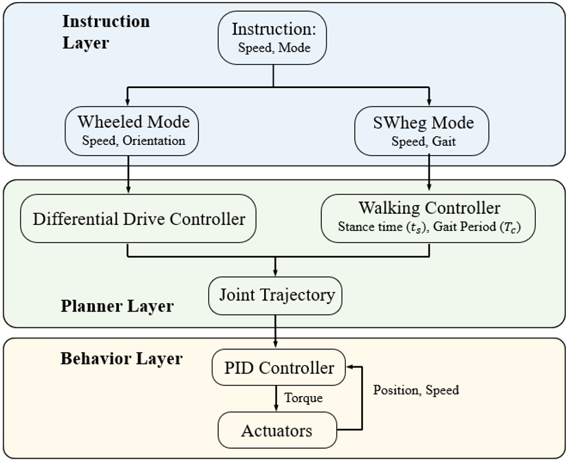
The control system consists of three layers: the instruction layer, the planner layer, and the behavior layer. The instruction layer processes high-level instructions, including control mode, walking gait, and moving speed. A finite state machine manages controllers of different modes. During mode transitions, the joints’ position and control mode will be adjusted accordingly. For now, the instructions are provided by a human operator. The desired speed, gait, and velocity are then sent to the controller of the corresponding mode. In the planner layer, the controller generates velocity/position trajectories for each joint according to the command. The behavior layer controls the actuators. The actuators will track the provided trajectory with PD controllers.
4.2 Wheeled mode
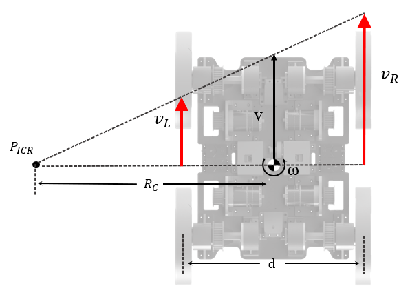
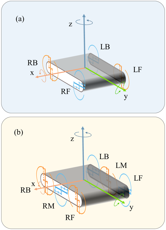
When the robot operates in wheeled mode, the control of the joints is straightforward. The rotation velocity () of each joint is assigned based on the differential-wheel steering model. Joints on the same side of the robot will be assigned the same angular velocity, or . As shown in Figure 8 when the robot has a forward velocity and a rotational velocity , its instant center of rotation will be located at point . The turning radius can be expressed as:
| (2) |
Then, the angular velocity of the joint on each side can be computed from
| (3) |
| (4) |
Where is the width of the chassis, and is the speed reduction ratio. The motions are shown in Figure 9. The wheeled mode control strategy can also be used in robots with more Wheel-legs.
4.3 Legged mode
In legged mode, the planner-layer controller will generate a group of clock-driven periodic trajectories for joints. This control strategy is joint space close-loop but task space open loop. The trajectories generated are periodic functions of time, which have outputs ranging from to .
4.3.1 Walking and Trotting
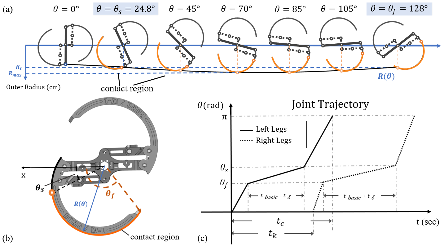
For walking and trotting, a simple Rhex-like control strategy is implemented. As shown in Figure 9 (a) and (c), the wheel-leg has a larger outer radius for (the highlighted part). We suppose that this part of rim is the contact region which will touch the ground and the rest of the rim won’t. In a cycle, a wheel-leg goes through a slow and a fast swing phase. A wheel-leg enters the slow phase when , and enters the fast phase when . The slow and fast phases are considered the stance and flight phases, respectively.
The Joint trajectory is shown in Figure 9(c). The joint trajectory of walking mode has two key parameters: , , which determine the ground speed of a wheel-leg. is the period of the function, and is the approximate stance time. Then, the average ground speed at which a wheel-leg moves the body during its stance phase is approximately:
| (5) |
All six legs have the same period, . The stance time of each wheel-leg can be expressed as . All wheel-legs have the same . wheel-legs on the same side of the robot have the same . Both and are proportional to the period. Then, the average ground speed provided by wheel-legs on one side can be expressed as:
| (6) |
Apply the differential wheeled model and we can have:
| (7) |
| (8) |
The forward linear velocity is mainly determined by . is a constant. To ensure the robot’s stability, should be carefully chosen. From experiments, we found that has a good performance on both quadrupedal and hexapod setup. By changing the we can roughly control the angular speed. Note that to keep the robot stable, the total stance time has a lower limit of .
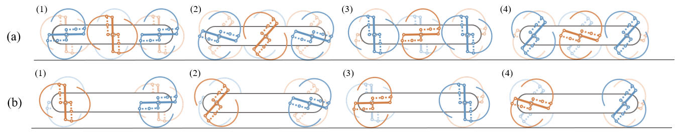
Different gaits can be generated by applying phase difference to the wheel-legs. The following table shows the phase difference of some simple gaits and the corresponding gait diagram. This control strategy can also be easily transferred to robots with more wheel-leg modules. The definition of wheel-leg is shown in Figure 11. Figure 10 shows the schematic of tripod gait and trotting gait.
| Gait Type | RF | RM | RR | LF | LM | LR |
|---|---|---|---|---|---|---|
| tripod | 0 | 0 | 0 |
| Gait Type | RF | RR | LF | LR |
|---|---|---|---|---|
| Walk | 0 | |||
| Trot | 0 | 0 |
4.3.2 Turning in place
The controller for in-place turning employs the same trajectories as in walking and trotting, except that the Legs on different sides rotate in opposite directions. The angular velocity of in-place turning mainly depends on the trajectory parameters and .
4.3.3 Synchronized Mode
A naive control strategy was designed for stair climbing tasks presented in Section 5.2. In this mode, the position of wheel-legs on the same axis (RF and LF, RM and LM, LB and RB) will be synchronized. Furthermore, to reduce the oscillation of the robot body, the Legs will rotate at a fixed velocity.
5 Experiments
In this section, the tendon-drive wheel-leg transformable module, and its performance on different terrains are evaluated.
5.1 Transformable Module Experiment
In this experiment, the accurate mapping between the servo’s rotation angle and the transformation extent, represented by the distance between as shown in Figure 12, is measured to ensure precise control over the transformation process. The rotational angle can be directly obtained from the built-in encoder of the servo. The distance is identified by AprilTags. As shown in Figure 12a, we placed the AprilTag at joints and , then used the calibrated camera to take pictures and calculate the spatial position of the two points and with respect to the camera coordinate system in the real world and calculate the distance between . Then we can solve for the distance between via geometric relationships. We performed repetitive expanding and retracting experiments and recorded the corresponding data, the average mapping is utilized as the transformation standard and is shown in Figure 12b.
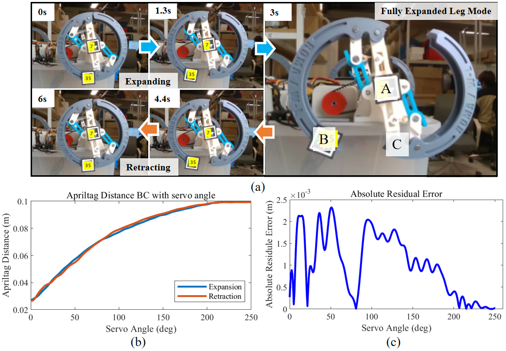
As shown in the absolute residual error plot given at the bottom right corner in Figure 12b, the maximum error is around , of the maximum distance between , which validated the stability of the transformation process.
5.2 Stair Ascending Experiment
To demonstrate the passability of the SWheg module on hard terrains, we tested the robot on two typical kinds of terrains: steps and stairs. The experiment is carried out in both simulation and real-world environments.
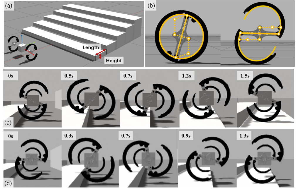
5.2.1 Simulation Setup
We conducted simulation experiments on the Gazebo simulation platform. The imported parts are generated from the original CAD file. However, to boost the speed of simulation, the -bar linkage close chain structure of the SWheg is replaced with a -bar open chain structure in the simulation model. (see Figure 13) The removed parts are wrapped up by the rims and have no contact with the ground during operation. The tendon-driven transformation system is also neglected. The transformation is done by direct joint position control. Only the collisions of SWhegs are calculated. The simulation model uses one set of SWhegs modules only.
5.2.2 Step Climbing Experiment
In this experiment, we tested the maximum terrain height difference that SWheg can overcome when using three operation modes: Wheeled, legged, and reversed-legged. In legged mode, SWheg contacts the ground surface with its curve part. In reversed-legged mode, the tip part hits the ground.
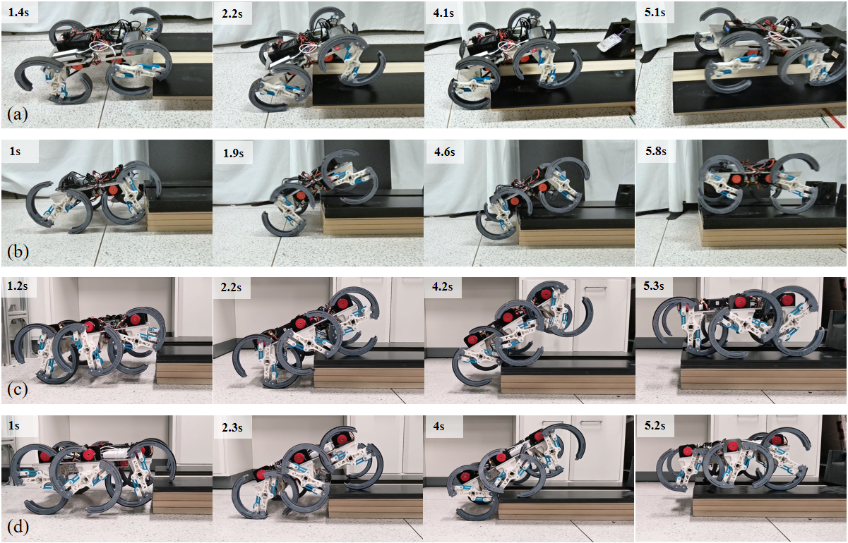
We performed experiments on steps of different heights and recorded the results. The pictures cut from the video are shown in Figure 13b. The test results of real robots (see Figure 15) are consistent with the simulation results. As shown in Table LABEL:tab:stepthreshold, the performance of the legged modes is significantly better than the wheeled mode.
| test mode | Wheel | Leg | Leg(reversed) |
|---|---|---|---|
| simulation | 8 mm | 13 mm | 18 mm |
| real | 8 mm | 14.7 mm | 16.8 mm |
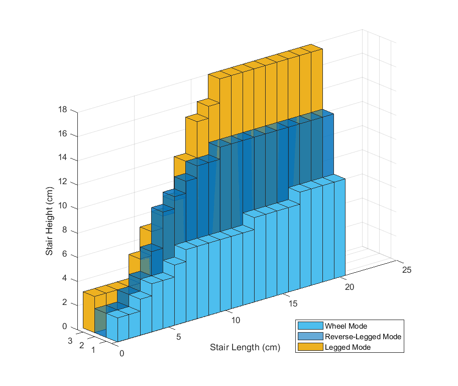
5.2.3 Stair Climbing Experiment
In this experiment, we tested the performance of SWhegs on continuous stairs. As shown in Figure 13, the two key parameters of stairs are stair depth and height.
In the simulation, we generated test environments in total. The stair models are automatically generated with xacro and have the same physics configurations. As shown in Figure 13, the stairs models are fixed to the world. Each test environment contains five stairs. Both height and length of stairs range from to . Additionally, a pose constraint is applied to the robots to ensure they face the stairs in the right direction.
The suggested operating zone (SOZ) is shown in Figure 14. Stair length will be the major constraint when it is small. When the stairs have enough length, the situation will be more likely to be the ’step’ situation. For stairs lower than , the Legged mode has the best performance. For higher stairs, only the reverted-legged mode can get over the stairs.
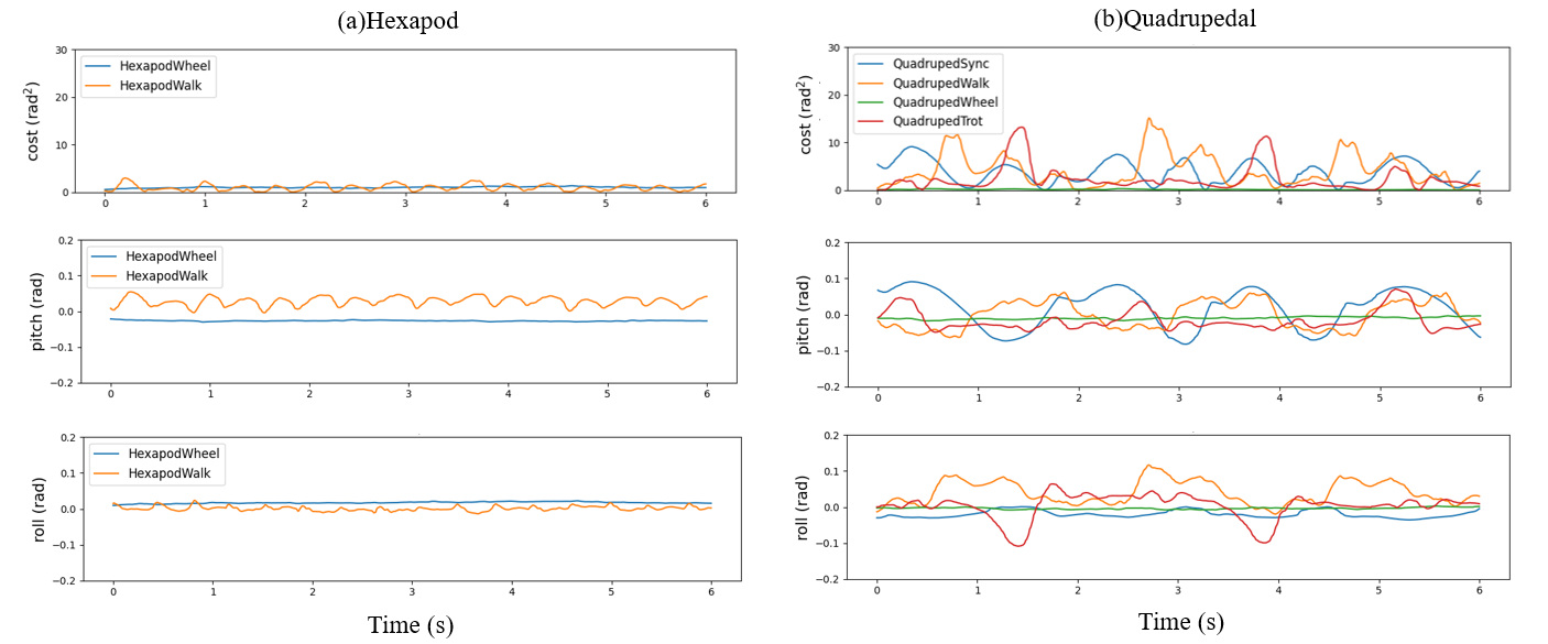
5.3 Motion Smoothness Experiment
In this experiment, we measured the stability of SWheg on the ground using different gaits. A WITMotion-HWT906 IMU is installed on the chassis of the robot. The body frame is defined in Figure 11. The robot’s orientation is represented by a set of Euler angles, . Where is the yaw, is the pitch, and is the roll. When the robot is operating on flat ground, the pitch and roll angle is supposed to be 0. So, the stability of motion is evaluated with a cost function, .
| (9) |
Where is a constant scaling factor. Here we take . Figure 16 shows the motion stability of hexapod and quadrupedal SWheg in a -seconds ( gait cycles of legged modes) operation on flat ground.
Both hexapod and quadruped SWheg have good stability when using wheeled mode. However, in legged modes, the tripod gait of the hexapod SWheg has better performance, which results from the internal stability of the hexapod configuration.
Performance of trotting and walking gait of quadrupedal SWheg significantly suffers due to the lack of support. Most quadruped wheel-leg transformable robots [8, 5, 7] use two or more actuators on each leg to acquire better stability. However, since we are using only one motor for each SWheg, the system is highly underactuated and unstable.
To achieve better stability on quadruped SWheg, combining walking mode with synchronized mode (see 4.3.1) is recommended. In synchronized mode, all four SWhegs have reliable contact with the ground. However, the synchronized mode lacks turning ability and must be used together with other walking modes.
5.4 Power Efficiency
5.4.1 Speed and Specific Resistance
Wheeled mode and legged mode have their locomotion characteristics on different terrains. Wheeled mode contact the ground continuously and has high movement performance on even terrain, while legged mode can pass on uneven terrains with its discontinuous characteristic. In this study, we combined the advantages of wheeled mode and legged mode by integrating both modes on a single platform with minimal actuator realization.
In previously studies on wheel-leg transformable robots, the power efficiency performance of the robots was evaluated using specific resistance(SR)[9]. For instance, Turboquad and Quattroped gave detailed SR performance of the platform on different surfaces (i.e. linoleum, asphalt, and grass) with different forward speeds.
For intuitive comparison, we evaluate the performance of the performance using SR as a standard. The experiment was conducted on each mode of quadrupedal and hexapod robot separately.
| (10) |
Where is the total weight of the robot, where the mass of quadrupedal SWheg and the hexapod SWheg is shown in Table 1. is the averaged forward speed, and is the averaged power consumption. The power consumption measured here is the total power consumed directly detected by a power measurement module. And this power consumption contains the power from all the actuators but not from the sensors and the processor.
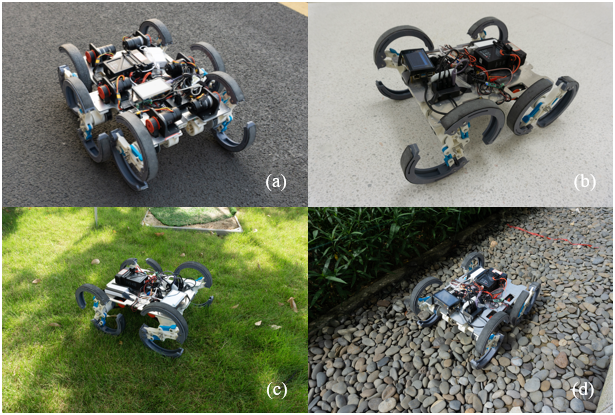
In this experiment, we tested two robots on different terrains(flat ground, asphalt, grass, pebbles) with legged mode and wheeled mode, which is shown in the Figure 17a,d, where three different gaits/modes for quadrupedal SWheg, including wheeled mode, trotting gait, and walking gait, two gaits/modes for hexapod SWheg, including wheeled mode and triangular gait. We recorded several powers and running times for each gait/mode and computed the forward velocity and specific resistance to plot the result on Figure 18.
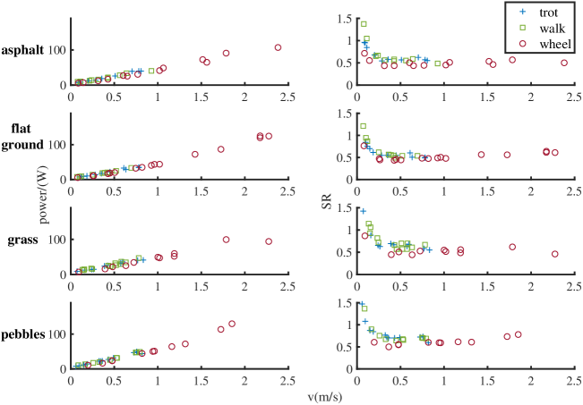
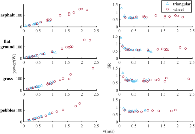
Overall power consumption is mainly determined by the behavior of motor operation. Figure 18 shows SR versus the forward speeds for two robots. Several conclusions can be derived as follows:
(1) For all forward speeds of the quadrupedal SWheg robot in four different terrains, the wheeled mode is more power efficient than other gaits, including walking gait and trotting gait. This result corresponds to our expectation, in the legged mode of quadrupedal SWheg, the robot need to consume more energy for the ground contact energy loss and the leg acceleration and deceleration which is based on position-based trajectory planning. But for the hexapod SWheg robot, the SR values are very similar in four different terrains for two locomotion modes, where the result is very different from that of the quadrupedal. The most likely reason is that when the hexapod Swheg robot moves in the triangular gait, there are always three legs touching the ground, in other words, due to the smoother motion of the triangular gait compared with other gaits, it minimizes the contact energy loss considerably.
(2) All the measurements in legged mode, i.e. trotting gait, walking gait, and triangular gait, were acquired in the speed range of about , yet the wheeled mode measurements were recorded in the speed range of . The reason is that the legged mode is using position-based trajectory planning and has an acceleration and deceleration process, and there is a big impact when the acceleration happened the ground contact, which increases the risk of robot damage. Despite this speed limit for legged mode, it still has better performance when encountering rough terrains with various obstacles. Based on this finding, we can land on the mode strategy for the SWheg robots: when moving in these four different terrains in the speed range of , use wheeled mode. When moving in rough terrains with obstacles, transforms into legged mode.
(3) The overall power consumption of the robot increases with the forward speed, but the specific resistance, i.e. cost of transport, decreases with faster speed. The power efficiency trend in four different terrains of quadrupedal and hexapod SWheg robots looks very similar. All of the SR values decrease evidently in the range of and after that tend to steadily. This result indicates that the robot is more energy-efficient in high-speed motion. The reason is that the SR value is a time-relevant value, when a robot moves slowly in the terrain, it consumes more energy on motor heat loss and so decreases the power efficiency.
(4) The type of terrain has a huge effect on power consumption. Both quadrupedal and hexapod SWheg robots are more power efficient on flat ground and asphalt compared with grass and pebble terrain, as the locomotion in rough terrains consumes more energy.
(5) In wheeled mode, the SR value of a hexapod SWheg robot is higher than that of the quadrupedal SWheg robot when moving in these four different terrains. One of the possible reasons is that when moving at the same speed in wheeled mode, the Hexapod SWheg robot has two more wheels in contact with the ground, and the corresponding friction force increases the cost of transport. In the legged mode, including the triangular gait of the hexapod SWheg robot, and the walking and trotting gait of a quadrupedal SWheg robot, the SR value is very much similar. This indicates that these gaits are equivalent power-efficiency-wise, and can be selected based on other criteria such as forward speed or motion smoothness.
5.4.2 Energy Consumption on long terrains
To validate SWhegs’ advantage of seamlessly integrating wheels and legs on a single platform, we conducted comparison tests on a long terrain consisting of various terrains using three different locomotion strategies, namely: only-wheel, only-leg, and wheel-leg integrated strategies. The tests were performed outdoors on a terrain containing grass, pebbles, flat ground, and stairs in the route. The only-wheel strategy fails at steps greater than the radius of the wheel. The only-leg strategy successfully finished the route, where the Quadruped robot used with energy consumption in total, hexapod SWheg robot used with energy consumption in total. In contrast, the wheel-leg integrated strategy took with energy consumption for quadruped and with energy consumption for hexapod. To sum up, this experiment validates the overall better performance of wheel-leg integrated platforms, which is the ability to overcome obstacles higher than wheel radius compared to only-wheel platforms and is faster and more energy efficient than only-leg platforms.
6 Conclusion and Future Work
This paper reported the design and performance evaluation of a novel modular wheel-leg transformable robot design with minimal actuator realization named SWheg. The robot can perform fast morphology transformation between wheels and S-shape legs using only actuators when compared to the literature designs. This greatly reduces system complexity, cost, and failure rate. The proposed design has a novel wheel-leg transformable module that uses tendon-driven motion mode switching and a tendon network that uses a single actuator to switch the motion mode of the entire robot. We built two platforms with four and six wheel-leg modules to validate our design principle and compared the performance of the platforms in both simulation and various terrains. Our robot shows great overall mobility and obstacle negotiation capability. In the future, we will further improve the design to make the system more reliable and easy to configure. We will also develop specialized behaviors to enable online gait transitions and faster movements. On the perception side, We will add sensing techniques to the platform such as depth camera and radar to enable the robot to classify and negotiate with different terrains by adjusting gaits and modes.
Acknowledgments
This work was supported in part by the Science, Technology and Innovation Commission of Shenzhen Municipality under grant no. ZDSYS20200811143601004.
References
- Agrawal et al., [2016] Agrawal, S. P., Dagale, H., Mohan, N., and Umanand, L. (2016). Ions: a quadruped robot for multi-terrain applications. Int. J. Mater. Mech. Manuf., 4:84–88.
- Bai et al., [2018] Bai, L., Guan, J., Chen, X., Hou, J., and Duan, W. (2018). An optional passive/active transformable wheel-legged mobility concept for search and rescue robots. Robotics and Autonomous Systems, 107:145–155.
- Campbell and Buehler, [2003] Campbell, D. and Buehler, M. (2003). Stair descent in the simple hexapod’rhex’. In 2003 IEEE International Conference on Robotics and Automation (Cat. No. 03CH37422), volume 1, pages 1380–1385. IEEE.
- Cao et al., [2022] Cao, R., Gu, J., Yu, C., and Rosendo, A. (2022). Omniwheg: An omnidirectional wheel-leg transformable robot. arXiv preprint arXiv:2203.02118.
- Chen et al., [2013] Chen, S.-C., Huang, K.-J., Chen, W.-H., Shen, S.-Y., Li, C.-H., and Lin, P.-C. (2013). Quattroped: a leg–wheel transformable robot. IEEE/ASME Transactions On Mechatronics, 19(2):730–742.
- [6] Chen, S.-C., Huang, K.-J., Chen, W.-H., Shen, S.-Y., Li, C.-H., and Lin, P.-C. (2014a). Quattroped: A leg–wheel transformable robot. IEEE/ASME Transactions on Mechatronics, 19(2):730–742.
- [7] Chen, S.-C., Huang, K.-J., Chen, W.-H., Shen, S.-Y., Li, C.-H., and Lin, P.-C. (2014b). Quattroped: A leg–wheel transformable robot. IEEE/ASME Transactions on Mechatronics, 19(2):730–742.
- Chen et al., [2017] Chen, W.-H., Lin, H.-S., Lin, Y.-M., and Lin, P.-C. (2017). Turboquad: A novel leg–wheel transformable robot with smooth and fast behavioral transitions. IEEE Transactions on Robotics, 33(5):1025–1040.
- Gabrielli, [1950] Gabrielli, G. V. T. (1950). What price speed? : specific power required for propulsion of vehicles.
- Kim et al., [2020] Kim, Y., Lee, Y., Lee, S., Kim, J., Kim, H. S., and Seo, T. (2020). Step: A new mobile platform with 2-dof transformable wheels for service robots. IEEE/ASME Transactions on Mechatronics, 25(4):1859–1868.
- Kim et al., [2013] Kim, Y.-S., Jung, G.-P., Kim, H., Cho, K.-J., and Chu, C.-N. (2013). Wheel transformer: A miniaturized terrain adaptive robot with passively transformed wheels. In 2013 IEEE International Conference on Robotics and Automation, pages 5625–5630.
- Kim et al., [2014] Kim, Y.-S., Jung, G.-P., Kim, H., Cho, K.-J., and Chu, C.-N. (2014). Wheel transformer: A wheel-leg hybrid robot with passive transformable wheels. IEEE Transactions on Robotics, 30(6):1487–1498.
- Kosugi et al., [1984] Kosugi, M., Ohya, T., and Migita, T. (1984). Motion analysis with experimental verification of the hybrid robot peopler-ii for reversible switch between walk and roll on demand. Chemischer Informationsdienst, 15(11):no–no.
- Lacagnina et al., [2003] Lacagnina, M., Muscato, G., and Sinatra, R. (2003). Kinematics, dynamics and control of a hybrid robot wheeleg. Robotics and Autonomous Systems, 45(3-4):161–180.
- Lee et al., [2017] Lee, D. Y., Kim, S. R., Kim, J. S., Park, J. J., and Cho, K. J. (2017). Origami wheel transformer: A variable-diameter wheel drive robot using an origami structure. Soft Robotics, 4(2):163–180.
- [16] Li, J., Qin, H., Wang, J., and Li, J. (2021a). Openstreetmap-based autonomous navigation for the four wheel-legged robot via 3d-lidar and ccd camera. IEEE Transactions on Industrial Electronics, 69(3):2708–2717.
- [17] Li, J., Wang, J., Peng, H., Hu, Y., and Su, H. (2021b). Fuzzy-torque approximation-enhanced sliding mode control for lateral stability of mobile robot. IEEE Transactions on Systems, Man, and Cybernetics: Systems.
- Marques et al., [2006] Marques, C., Cristóvão, J., Lima, P., Frazao, J., Ribeiro, I., and Ventura, R. (2006). Raposa: Semi-autonomous robot for rescue operations. In 2006 IEEE/RSJ International Conference on Intelligent Robots and Systems, pages 3988–3993. IEEE.
- Mertyüz et al., [2020] Mertyüz, R., Tanyldz, A. K., Taar, B., Tatar, A. B., and Yakut, O. (2020). Fuhar: A transformable wheel-legged hybrid mobile robot. Robotics and Autonomous Systems, 133.
- Moore et al., [2002] Moore, E., Campbell, D., Grimminger, F., and Buehler, M. (2002). Reliable stair climbing in the simple hexapod’rhex’. In Proceedings 2002 IEEE International Conference on Robotics and Automation (Cat. No. 02CH37292), volume 3, pages 2222–2227. IEEE.
- Moriya et al., [2020] Moriya, N., Shigemune, H., and Sawada, H. (2020). A robotic wheel locally transforming the diameter for the locomotion on rough terrain. In 2020 IEEE International Conference on Mechatronics and Automation (ICMA), pages 1257–1262.
- Nakajima et al., [2004] Nakajima, S., Nakano, E., and Takahashi, T. (2004). Motion control technique for practical use of a leg-wheel robot on unknown outdoor rough terrains. In International Conference on Intelligent Robots and Systems.
- Poomarin et al., [2016] Poomarin, W., Chancharoen, R., and Sangveraphunsiri, V. (2016). Automatic docking with obstacle avoidance of a differential wheel mobile robot. International Journal of Mechanical Engineering and Robotics Research, 5(1):11.
- Ryu et al., [2020] Ryu, S., Lee, Y., and Seo, T. (2020). Shape-morphing wheel design and analysis for step climbing in high speed locomotion. IEEE Robotics and Automation Letters, 5(2):1977–1982.
- Saranli, [2001] Saranli, U. (2001). Rhex: A simple and highly mobile hexapod robot. The International Journal of Robotics Research, 20(7):616–631.
- Saranli et al., [2000] Saranli, U., Buehler, M., and Koditschek, D. E. (2000). Design, modeling and preliminary control of a compliant hexapod robot. In Proceedings 2000 ICRA. Millennium Conference. IEEE International Conference on Robotics and Automation. Symposia Proceedings (Cat. No. 00CH37065), volume 3, pages 2589–2596. IEEE.
- Soyguder and Boles, [2017] Soyguder, S. and Boles, W. (2017). Slegs robot: development and design of a novel flexible and self-reconfigurable robot leg. Industrial Robot: An International Journal.
- Sun et al., [2017] Sun, T., Xiang, X., Su, W., Wu, H., and Song, Y. (2017). A transformable wheel-legged mobile robot: Design, analysis and experiment. Robotics and Autonomous Systems, 98:30–41.
- Tadakuma et al., [2010] Tadakuma, K., Tadakuma, R., Maruyama, A., Rohmer, E., Nagatani, K., Yoshida, K., Ming, A., Shimojo, M., Higashimori, M., and Kaneko, M. (2010). Mechanical design of the wheel-leg hybrid mobile robot to realize a large wheel diameter. In 2010 IEEE/RSJ international conference on intelligent robots and systems, pages 3358–3365. IEEE.
- Wang et al., [2021] Wang, S., Chen, Z., Li, J., Wang, J., Li, J., and Zhao, J. (2021). Flexible motion framework of the six wheel-legged robot: Experimental results. IEEE/ASME Transactions on Mechatronics.
- Zheng and Lee, [2019] Zheng, C. and Lee, K. (2019). Wheeler: Wheel-leg reconfigurable mechanism with passive gears for mobile robot applications. In 2019 International Conference on Robotics and Automation (ICRA), pages 9292–9298.