Bolometric detection of Josephson inductance in a highly resistive environment
I Abstract
The Josephson junction is a building block of quantum circuits. Its behavior, well understood when treated as an isolated entity, is strongly affected by coupling to an electromagnetic environment. In 1983, Schmid predicted that a Josephson junction shunted by a resistance exceeding the resistance quantum k for Cooper pairs would become insulating since the phase fluctuations would destroy the coherent Josephson coupling. However, recent microwave measurements have questioned this interpretation. Here, we insert a small Josephson junction in a Johnson-Nyquist-type setup where it is driven by weak current noise arising from thermal fluctuations. Our heat probe minimally perturbs the junction’s equilibrium, shedding light on features not visible in charge transport. We find that the Josephson critical current completely vanishes in DC charge transport measurement, and the junction demonstrates Coulomb blockade in agreement with the theory. Surprisingly, thermal transport measurements show that the Josephson junction acts as an inductor at high frequencies, unambiguously demonstrating that a supercurrent survives despite the Coulomb blockade observed in DC measurements.
II Introduction
Thermal transport by photons in electrical circuits arises from Johnson-Nyquist noise [1, 2] between two resistive elements at unequal temperatures. The resulting current noise flowing in the ideally lossless circuit linking the two resistors provides an efficient thermalization and energy exchange channel at very low temperatures [3, 4]. This current noise can be modulated by adding a suitable tunable dissipationless element in the circuit, which can conveniently be implemented by a magnetically [4, 5, 6] or electrically [7] controlled Josephson device. So far, both theoretical [8, 9] and experimental approaches [4, 5, 6, 7] of photonic heat transport have only considered on-chip resistors with resistance much smaller than the superconducting resistance quantum , where the environmental back-action effect on the junctions is weak. More fundamentally, energy transport at different frequencies through quantum coherent systems strongly coupled to a resistive environment, characterized by the dissipation strength , remains largely unexplored [11, 12].
It is well-established that the electrical transport properties of a superconducting junction depend on the electromagnetic environment in which it is embedded. Charge transport through a tunnel junction in an Ohmic environment with resistance comparable to the resistance quantum is suppressed at low voltage bias and temperature because of Coulomb blockade [13], and the extension of this phenomenon to superconducting junctions, which are intrinsically phase-coherent, comes naturally [14, 15, 13, 18]. Recent experiments using this effect include the production of antibunched photons at high rates [19] and suppressing the Andreev bound state-induced zero bias anomaly, which could be beneficial in the arduous search for Majorana quasiparticles [20]. For a Josephson junction shunted by a resistor with resistance exceeding , the supercurrent peak (i.e., current at zero applied voltage bias) is predicted to disappear, being shifted to finite voltage as a result of inelastic Cooper pair tunneling [13]. This is accompanied by a sub-linear current-voltage characteristic as at low bias voltages and extremely low temperature, specifically when , with the Boltzmann constant, the charging energy, and the elementary charge. According to the theory, a phase transition should occur at . This transition, which can be associated with the one predicted by Schmid [21] and Bulgadaev [22], was first tested in DC charge transport experiments [14, 23, 18, 16, 17]. However, recent admittance measurements of small junctions, shunted by a highly Ohmic environment [24] called into question the scenario of a dissipative phase transition, leading to further debate about the very existence of this transition [25, 26, 27, 28, 29, 30].
In this context, we present a heat transport experiment in which a small tunable junction (effectively a superconducting quantum interference device SQUID) is embedded in a Johnson-Nyquist setup with hot and cold resistors with resistances to explore this regime. The SQUID geometry enables magnetic-flux control of the photonic heat current [4]. It is intended to demonstrate the destruction or resilience of the Josephson coupling through the observations of heat flow oscillations, or lack thereof if the junctions are truly insulating. We find that the magnitude of heat current flowing from one resistor to another remains close to the value given by the quantum limit, and it exhibits clear oscillations with the external magnetic flux, similar to the systems embedded in a low impedance environment [4]. While this observation might point towards the survival of a supercurrent at high frequencies, a control experiment on DC charge transport (angular frequency ) shows clear suppression of the charge current at low voltage bias caused by the environmental Coulomb blockade, in line with theoretical predictions and previous experimental results [14, 23]. This apparent contradiction, highlighting the role of heat transport as a complementary probe when many-body correlations are present [31, 32], is discussed within the existing theoretical and experimental literature.
III Results
III.1 Experimental setup
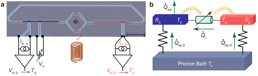
Our device (see Fig. 1a for an SEM image) consists of a SQUID between two nominally identical on-chip thin chromium (Cr) resistors acting as thermal baths, from now on referred to as (hot) drain and (cold) source with resistances denoted by and , respectively. Each arm of the SQUID is galvanically connected to one source and drain resistor of volume m3 and whose resistance is nominally equal to that of an independently measured resistor with same dimensions on the same chip, with a value k (see Supplementary S1). The distance between the SQUID and the resistors is kept short (a few microns) to avoid suppression of environment-induced effects via stray capacitance. The series configuration of the SQUID and resistors is further closed into a loop by a superconducting line. This warrants efficient electromagnetic heat transport through improved impedance matching [33]. The clean contact between chromium and superconducting aluminum leads (see Supplementary S2) serves as an Andreev-mirror [34], which enables essentially perfect conversion to charge transport by Cooper pairs in the superconducting strips while effectively suppressing quasiparticle heat diffusion along them at low temperatures ( mK for aluminum) [33]. Four external superconducting leads are contacted with the source resistor through a thin oxide barrier, forming NIS-tunnel junctions. A pair of these junctions is used to measure the electronic temperature (in the case of quasi-equilibrium where the electron temperature is well-defined [35]) by applying a small DC-current bias through it, whereas another pair is used to locally cool the resistor when voltage-biased [35]. The electron temperature of the drain resistor is measured simultaneously by another SINIS junction structure, as depicted in Fig. 1a. We have presented data on two samples, henceforth called Sample I and Sample II.
III.2 DC measurements of the replica sample
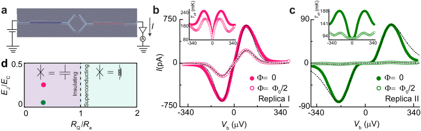
We first measure the current-voltage characteristics (IVC) of a reference sample (see Fig. 2a) on the same chip, made during the same fabrication run, from now on called “Replica”, with nominally equal parameters as the main sample. This provides estimates of parameters for the heat transport experiments and enables comparison between charge and heat transport behavior. Note that although the geometries of the samples used for these measurements are slightly different, the central part of the two samples (resistors + SQUID) are nominally identical. In the sample used for the heat transport experiment, the superconducting loop keeps the current noise flowing within a closed loop and helps us define the noise power transmission coefficient.
Figure 2b and 2c show the IVC for the two Replica samples at a phonon temperature of mK in the low bias region at two different magnetic flux values (solid circles) and (open circles) with the superconducting magnetic flux quantum. Suppression with respect to the unblocked case is observed in the low-bias DC current through the SQUID, which is more robust for Replica II (panel c) due to its higher charging energy . This observation is well understood in the framework of dynamical Coulomb blockade [13]: the resistive environment impedes charge relaxation after a Cooper-pair tunneling event through junctions with high charging energy, which translates to a conductance reduction at low energy. The value of (0.6 K for Replica I and 1.4 K for Replica II) is extracted from the current peak feature appearing in the IVC, which for small Josephson junctions in contact with an resistive environment with occurs at a voltage bias [36, 14]. The Josephson energy is estimated by using the Ambegaokar-Baratoff relation as (0.07 K for Replica I and 0.03 K for Replica II), with V the aluminum superconducting energy gap and the quasiparticle tunnel resistance of the SQUID. This resistance is obtained experimentally, see Supplementary S3 for more details.
The dashed lines in Fig. 2b and 2c are the theoretical results obtained by the standard P(E) theory [13] under the condition in an RC-environment, which highlights the effect of the electromagnetic environment on Josephson phase fluctuations (see Supplementary S4). Despite the fact that the condition is not well satisfied for either of the two samples, one can use a simple rule: if the Josephson energy is less than Josephson energy obtained from Ambegaokar-Baratoff (which is our case), then theory should still hold regardless of the condition and the relatives’ magnitudes of and [37]. In these calculations, we include overheating caused by the applied bias, as depicted in the inset of Figs. 2b and 2c, resulting in good agreement with the data at low voltage bias. However, a noticeable discrepancy is observed at high voltages for Replica II. A possible reason for this discrepancy could be that, at voltage beyond , the Josephson frequency is high, GHz: in this range, the impedance of the environment may significantly differ from our simple RC model. Furthermore, at these voltages closer to the superconducting gap quasiparticles can contribute but are not included in P(E) theory. On the other hand, the data at is fitted by considering an asymmetry factor of the SQUID critical current for Replica I and for Replica II, respectively. Note that the Josephson energy is a fitting parameter in the model. Finally, Fig. 2d shows the Schmid phase diagram with the two points related to each Replica sample, showing their insulating character as expected.
III.3 Heat transport measurements
With these results as a reference, we now turn to heat transport measurements, the main focus of this work. The power flowing from drain to source under a thermal gradient is determined by measuring the electronic temperatures of the drain and the source . The temperature difference is generated by DC biasing the source resistor with a voltage that enables electronic cooling of the source by removal of hot electrons [35, 33]. This effect can be observed in Fig. 3a and 3b, for the two samples at a fixed temperature in each case. In steady-state, these temperatures involve the different energy relaxation channels in the system, as illustrated in the thermal model that accounts for our setup shown in Fig. 1b. By energy conservation, a direct relation (valid at temperatures when quasiparticle heat diffusion along the superconductor is exponentially suppressed [33]), between and the temperatures () measured in the system is found
| (1) |
where is the electron-phonon heat current governed by the drain resistor. Here, is the electron-phonon coupling constant of the normal metal, which was measured independently to be WK-5.93m-3, see Supplementary S1. With our experimental setup (see Fig. 1a), we have full control of all temperatures and, therefore, the powers involved in the system, leading to an accurate and fully calibrated measurement of the thermal conductance between the drain and source.
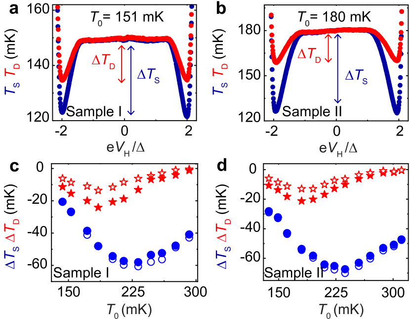
Figure 3a and 3b show the measured electronic temperature of the source and drain resistor with the applied voltage bias for each sample at a representative phonon temperature . Notably, both samples show a significant decrease in the source and drain electronic temperature when the voltage approaches , indicating that the cooling power of the SINIS refrigerator reaches its maximum [35]. Figure 3c and 3d show the temperature drops , i= S, D at the maximum cooling bias of the SINIS for the two samples at two different magnetic flux values. At , the electronic temperature equals the phonon temperature . These drops characterize the thermal coupling between the drain and source, i.e., the thermal conductance from drain to source. Source and drain temperature drops differ for the two magnetic fluxes supplied. This difference is more evident in the temperature drops of the drain, where the drop at is noticeably weaker than at at low temperatures, indicating that the photonic channel effectively dominates the transport mechanism at lower temperatures [33]. The significant flux-tunability of the remote cooling process is a characteristic feature of SQUID interference [4], which suggests that the environmental back-action does not destroy the Josephson coupling at zero DC voltage bias. As increases above 200 mK, the photon thermal coupling gets smaller with respect to electron-phonon coupling.
To quantify the power transferred from the drain to the source resistor through a photon channel, the electronic temperatures measured on the two baths have been converted to heat current by using Eq. (1) and compared with the maximum power that can be transmitted through a single ballistic channel given by [38].
The photonic heat current for the two samples in the temperature range of 140 - 200 mK is shown in Figs. 4a and 4b. For Sample I at (solid circles), the energy is transferred from the drain to the source at a rate very close to that dictated by the quantum of thermal conductance (solid black line). Nevertheless, a minor deviation of from the quantum limit prediction is seen for Sample II. As expected, as soon as the magnetic flux is switched on and reaches the half flux quantum (star symbols), the heat current for both samples tends to decrease due to weaker photonic coupling [33].
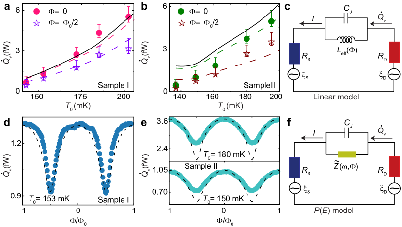
We then confront the data with theoretical calculations based on the Landauer relation for heat current from drain to source [3],
| (2) |
where is the transmission probability of the thermal radiation from the drain to the source at angular frequency . In the limit of small phase fluctuations around a given average phase bias , the SQUID can conveniently be approximated by a harmonic oscillator. In electrical terms, this translates to an effective phase-dependent Josephson inductance in parallel with a capacitance (see Fig. 4c), where is an average over phase fluctuations [39, 27]. Within this linear model, and by assuming the lumped approximation (valid since the dominant radiation wavelength cm at 150 mK is much larger than the circuit characteristic dimensions m), the power transmission coefficient can be explicitly written [3, 9] as (see methods), with the frequency-dependent total series impedance of the circuit. In this framework, the maximum heat transfer is expected for a perfect impedance matching when = and when the phase fluctuations are small, i.e., under no net electrical bias. However, for strong phase fluctuations at high resistances , one naively expects the average value of the cosine almost to vanish, . Indeed, we have shown above that the DC charge transport measurements of the Replica are well described by the usual theory of Coulomb blockade, which implies . Assuming this, the SQUID can be regarded as a parallel connection of a capacitor and of high effective impedance , see Fig. 4f. Then the modulation of the Josephson coupling by flux almost does not affect the transmission probability , and the oscillations of the heat flow are expected to be very small. Below we will show that the strong modulation of the heat flux observed in our experiment is consistent with the assumption of nonvanishing rather than with . This finding is similar to that in the recent study conducted by Pechenezhskiy et. al., [40] on a fluxonium qubit shunted by a high impedance environment in which they have revealed the presence of non-vanishing ground state renormalization in the divergence inductance limit and the Bloch band structure of a single Josephson junction with , which leads to modulations in the transition frequency with the external magnetic flux. Our work, combined with theirs, will be useful in developing a general theory that can clarify the dynamics of a Josephson junction at finite frequencies in a high impedance environment.
The dashed lines displayed in figures 4a and 4b are the theoretical results obtained by solving Eq. (2) within the linear model for the corresponding magnetic fluxes applied. For Sample I, reasonable agreement with the experimental data at is found if we use the bare Josephson junction inductance in the calculated . Nevertheless, for Sample II, a significant deviation from the data is observed as the temperature is lowered. This deviation can be captured if we set the re-normalization parameter . Using the renormalization as a free parameter in the fitting is a simple, phenomenological way to emphasize that , which is unexpected for small Josephson junctions in series with a large resistance when considering the DC behaviour. Regardless of the value used, these oscillations indicate that the photonic heat exchange from the drain to the source, i.e., current noise over a bandwidth GHz, is mainly transmitted through the Josephson inductor channel, which acts as a low-pass filter. At (dashed purple and dark red lines), the power is reduced as expected, in fair agreement with the data. In this regime, the Josephson critical current is vanishingly small (making the inductance essentially infinite at the relevant frequencies); consequently, the power transmitted from the drain to the source takes place mainly through the junction capacitance , which acts as a high-pass filter in the transmission and thus only enables a small fraction of the thermal fluctuations to be transmitted as current in the circuit. The calculation was performed using an asymmetry parameter (which does not coincide with that obtained for replica I, but matches much better the closed SQUID data in heat transport) for sample I and is coincidentally the same for sample II. Furthermore, the heat current calculated within the P(E) theory at shows a decrease of to the level of the power obtained in the linear model at (see Supplementary Figs. S5b and S5c).
Figure 4d and Fig. 4e show the heat current modulations measured at given phonon temperatures for samples I and II, respectively. Clear oscillations with period are observed. This result unequivocally demonstrates that the inductive response of the junction persists in the presence of strong environmental back-action, in contrast to what is observed for charge transport measurements in the Replica. The data is again compared to the theoretical models proposed. On the one hand, for the two examples presented, the heat current modulations are qualitatively captured with the linear model if we use a value of for sample I and for the modulations at mK, and at mK in sample II, and keeping the asymmetry parameter same as before. On the other hand, the oscillation amplitude predicted by P(E) theory (for which ) is much smaller than the amplitudes observed (see Supplementary Figs. S5d and S5e).
Let us now focus on the discrepancy between charge and heat transport measurements. One obvious difference resides in the relevant frequency range: at zero frequency, theory of Coulomb blockade describes incoherent Cooper pair tunneling through the junction, and the transition to an insulating state predicted by Schmid and Bulgadaev is observed as becomes greater than . On the other hand, heat transport deals with non-zero frequency current fluctuations flowing through the junction at zero net voltage bias. This was considered previously [41] through an extension of the static version of theory to finite frequency transport. The derivation relies on the hypothesis of very weak Josephson coupling, . This condition is not well satisfied for both samples. However, this point can hardly justify our contradicting observations: indeed, the discrepancy is the strongest for sample II (as highlighted by the sharp Coulomb gap observed in DC charge transport, see Fig. 2c), where we are closer to this limit. An alternative, motivated by the microscopic description of the Josephson junction in an arbitrary electromagnetic environment [39], is the existence of an inductive-like shunt in the junctions’ environment, fundamentally due to the BCS gap, which protects the ground state of the junction from strong phase diffusion. The presence of such a shunt would translate as a finite supercurrent peak, which indeed was reported recently [19]. Its absence in our charge measurement (and previous ones [14, 23]) contradicts this interpretation.
Note that recent high-frequency measurements of a small Josephson junction in an engineered high impedance environment have revealed the inelastic nature of the scattering process of a photon off the junction [42]. The conceptual similarity between the setup considered there and ours suggests that the description of the junction as a renormalized inductor [39], while useful for a basic understanding, is too simplistic because the nonlinearities of the junctions are present due to strong phase fluctuations. Nevertheless, our bolometric technique collects photons at energies over a bandwidth and, therefore, would not distinguish between several down-converted photons out of an inelastic process or a single elastically scattered photon.
In summary, we have experimentally demonstrated through heat transport measurements that a Josephson junction acts as an inductor even in the presence of a highly resistive environment. Though the interpretation of the dissipative transition can be debated [24, 27], the discrepancy between the heat transport measurements and the control charge transport measurements by us here and in previous works [14, 23, 43], cannot be accounted for by the existing theory and calls for further developments, both experimental and theoretical. Our findings are important not only from the fundamental physics point of view but also for future applications such as microbolometers or heat sink designs in quantum circuits. On a practical side, we note that any design aiming at increasing resistances for improved, quantum-limited tunable remote electronic cooling [4, 33] is much less sensitive to back-action effects than initially anticipated.
IV Methods
Device fabrication and measurement
The devices were fabricated on 4-inch silicon substrates covered by nm of Si/SiO2 in an electron beam lithography (EBL, Vistec EBPG500 + operating at kV) using a Ge-based hard mask process and the conventional shadow evaporation technique [44]. The silicon wafer was coated with 400 nm layers of poly(methylmethacrylate-methacrylate acid) P(MMA-MAA) resist spun for 1 min at 5500 rpm and baked at 180 ∘C for 20 min, twice. Then, on top of it 22 nm Ge layer was deposited in an electron-beam evaporator, and right after, approximately 50 nm thick of PMMA was coated with spun at 2500 rpm for 1 min and baked at 160 ∘C for 1 min. The devices were patterned on the PMMA layer by using electron beam lithography, and afterward, it was developed using a mixture solution with a concentration of 1:3 of methyl-isobutyl-ketone+isopropanol (MIBK). This pattern is transferred to the Ge mask using reactive ion etching (RIE) with tetrafluoromethane CF4 plasma. The undercut in the MMA resist was created by oxygen plasma in the same RIE chamber. The metallic parts were made in three evaporation steps: first, a 20 nm layer of Al is evaporated at an evaporation angle of . Then, static oxidation in-situ with pressure around 3 mbar for 3 minutes is made. This step defines the superconducting finger used as a thermometer, heater, and branch of the SQUID. In the second step, a 20 nm layer of Al is evaporated at an angle of , forming the SQUID and the clean superconducting contact. Finally, a 14 nm layer of Cr is evaporated at an angle of comprising the thermal bath. The nominal loop area of the SQUID for the two samples was 25 m2. The main difference between them lies in the overlap area of the Josephson junction (JJ), which for Sample I is nominally 130140 nm2 and for Sample II is 8585 nm2. The resist was lifted-off in acetone at C. Then, the sample is attached to a sample carrier to be electrically connected to it by Al wire bonds for being measured. The bonded sample is placed on a stage with a double brass enclosure that acts as a radiation shield. It is connected to the mixing chamber of a custom-made plastic dilution refrigerator with a base temperature of approximately 40 mK. DC signals were applied through cryogenic signal lines filtered with lossy coaxial cables with 0-10 kHz bandwidth connected to the bonded sample through a room-temperature breakout box. In order to sweep the SQUID Josephson energy, a perpendicular magnetic field is supplied by applying DC current to an external superconducting magnet inserted around the vacuum can. All the input signals were applied and read out using programmable sources and multimeters. Amplifying current and voltage output signal was accomplished using a room temperature low noise current amplifier Femto DDPCA-300 and voltage amplifier Femto DLVPA-100-F-D, respectively. The cryostat temperature is controlled by applying a voltage across the heater resistance attached to the mixing chamber. The calibration of thermometers was done by monitoring the voltage drop across the SINIS configuration (current biased pA) at zero heating bias voltage while varying the cryostat temperature up to 500 mK [35].
Photon transmission coefficient
As mentioned in the main text, the transmission probability of the thermal radiation from the source and drain used is Eq. (2) has been calculated within the two models. In the linear model approximation, can be written as
| (3) |
with
| (4) |
In the charge dominated regime () and taking into account the effect of the environment resistors through P(E) function, the transmission probability for the system studied reads [11],
| (5) |
where is the effective frequency-dependent impedance and, the functions and represent the probability of photon absorption in the source and the drain resistors, respectively. These functions are defined as
| (6) |
here l = S, D and is the phase-phase correlation function given by [13]:
| (7) |
The effective impedance is defined as
| (8) |
where is the P-function of the effective environment defined by the convolution of the P(E)-function of the two resistors,
| (9) |
V Data availability
The findings of this study can be supported with data that is accessible upon a reasonable request from the corresponding author.
VI References
References
- [1] Nyquist, H. Thermal agitation of electric charge in conductors. Phys. Rev. 32, 110 (1928).
- [2] Johnson, J. B. Thermal agitation of electricity in conductors. Phys. Rev. 32, 97 (1928).
- [3] Schmidt, D. R., Schoelkopf, R. J. & Cleland, A. N. Photon-mediated thermal relaxation of electrons in nanostructures. Phys. Rev. Lett. 93, 045901 (2004).
- [4] Meschke, M., Guichard, W. & Pekola, J. P. Single-mode heat conduction by photons. Nature. 444, 187–190 (2006).
- [5] Partanen, M. et al. Flux-tunable heat sink for quantum electric circuits. Sci. Rep. 8, 1–9 (2018).
- [6] Ronzani, A. et al. Tunable photonic heat transport in a quantum heat valve. Nat. Phys. 14, 991–995 (2018).
- [7] Maillet, O. et al. Electric field control of radiative heat transfer in a superconducting circuit. Nat. Commun. 11, 1–6 (2020).
- [8] Ojanen, T. & Jauho, A.-P. Mesoscopic photon heat transistor. Phys. Rev. Lett. 100, 155902 (2008).
- [9] Pascal, L. M. A, Courtois, H. & Hekking, F. W. J. Circuit approach to photonic heat transport. Phys. Rev. B. 83, 125113 (2011).
- [10] Kuzmin, R. et al. Quantum electrodynamics of a superconductor-insulator phase transition. Nat. Phys. 15, 930–934 (2019).
- [11] Thomas, G., Pekola, J. P. & Golubev, D. S. Photonic heat transport across a Josephson junction. Phys. Rev. B. 100, 094508 (2019).
- [12] Léger, S. et al. Observation of quantum many-body effects due to zero point fluctuations in superconducting circuits. Nat. Commun. 10, 1–8 (2019).
- [13] Ingold, G.-L. & Nazarov, Y. V. Charge tunneling rates in ultrasmall junctions. (Springer) 21–107 (1992).
- [14] Kuzmin, L. S et al. Coulomb blockade and incoherent tunneling of Cooper pairs in ultrasmall junctions affected by strong quantum fluctuations. Phys. Rev. Lett. 67, 1161 (1991).
- [15] Averin, D. V., Nazarov, Y. V. & Odintsov, A. A. Incoherent tunneling of the Cooper pairs and magnetic flux quanta in ultrasmall Josephson junctions. Phys. B Condens. Matter. 165, 945–946 (1990).
- [16] Yagi, R., Kobayashi, S., and Ootuka, Y.. Phase diagram for superconductor-insulator transition in single small Josephson junctions with shunt resistor. JPSJ 66, 3722–3724 (1997).
- [17] Penttilä, J et al. Experiments on dissipative dynamics of single Josephson junctions. J. Low Temp. Phys. 125, 89–114 (2001).
- [18] Corlevi, S. et al. Phase-charge duality of a Josephson junction in a fluctuating electromagnetic environment. Phys. Rev. Lett. 97, 096802 (2006).
- [19] Grimm, A. et al. Bright on-demand source of antibunched microwave photons based on inelastic Cooper pair tunneling. Phys. Rev. X. 9, 021016 (2019).
- [20] Zhang, S. et al. Suppressing Andreev bound state zero bias peaks using a strongly dissipative lead. Phys. Rev. Lett. 128, 076803 (2022).
- [21] Schmid, A. Diffusion and localization in a dissipative quantum system. Phys. Rev. Lett. 51, 1506 (1983).
- [22] Bulgadaev, S. A. Phase diagram of a dissipative quantum system. JETP Lett. 39, 264–267 (1984).
- [23] Penttilä, J. S. et al. “Superconductor-Insulator transition” in a single Josephson junction. Phys. Rev. Lett. 82, 1004 (1999).
- [24] Murani, A. et al. Absence of a dissipative quantum phase transition in Josephson junctions. Phys. Rev. X. 10, 021003 (2020).
- [25] Hakonen, P. J. & Sonin, E. B. Comment on “Absence of a Dissipative Quantum Phase Transition in Josephson Junctions”. Phys. Rev. X. 11, 018001 (2020).
- [26] Murani, A. et al. Reply to “Comment on ‘Absence of a Dissipative Quantum Phase Transition in Josephson Junctions’ ”. Phys. Rev. X. 11, 018002 (2021).
- [27] Masuki, K. et al. Absence versus Presence of Dissipative Quantum Phase Transition in Josephson Junctions. Phys. Rev. Lett. 129, 087001 (2022).
- [28] Sépulcre, T., Florens, S. & Snyman, I. Comment on “Absence versus Presence of Dissipative Quantum Phase Transition in Josephson Junctions”. Preprint at https://doi.org/10.48550/arXiv.2210.00742 (2022).
- [29] Masuki, K. et al. Reply to ’Comment on “Absence versus Presence of dissipative quantum phase Transition in Josephson Junctions”. Preprint at https://doi.org/10.48550/arXiv.2210.10361 (2022).
- [30] Kuzmin, R.et al. Observation of the Schmid-Bulgadaev dissipative quantum phase transition. Preprint at https://doi.org/10.48550/arXiv.2304.05806 (2023).
- [31] Giazotto, F. & Martínez-Pérez, M. J. The Josephson heat interferometer. Nature. 492, 401–405 (2012).
- [32] Sivre, E. et al. Heat Coulomb blockade of one ballistic channel. Nat. Phys. 14, 145–148 (2018).
- [33] Timofeev, A. et al. Electronic refrigeration at the quantum limit. Phys. Rev. Lett. 102, 200801 (2009).
- [34] Andreev, A. F. Thermal conductivity of the intermediate state of superconductors II. Sov. Phys. JETP. 20, 1490 (1965).
- [35] Giazotto, F. et al. Opportunities for mesoscopic in thermometry and refrigeration: Physics and applications. Rev. Mod. Phys. 78, 217 (2006).
- [36] Devoret, M. et al. Effect of the electromagnetic environment on the Coulomb blockade in ultrasmall tunnel junctions. Phys. Rev. Lett. 64, 1824 (1990).
- [37] Lu, Wen-Sen et al. Phase diffusion in low- Josephson junctions at millikelvin temperatures. Electronics 12, 416 (2023).
- [38] Pendry, J. Quantum limits to the flow of information and entropy. J. Phys. A Math: Mathematical and General. 16, 2161 (1983).
- [39] Joyez, P. Self-consistent dynamics of a Josephson junction in the presence of an arbitrary environment. Phys. Rev. Lett. 110, 217003 (2013).
- [40] Pechenezhskiy, I., et al.. The superconducting quasicharge qubit. Nature. 585, 368–371 (2020).
- [41] Saira, O. P. et al. Dispersive Thermometry with a Josephson Junction Coupled to a Resonator. Phys. Rev. Applied. 6, 024005 (2016).
- [42] Kuzmin, R. et al. Inelastic Scattering of a Photon by a Quantum Phase Slip. Phys. Rev. Lett. 126, 197701 (2021).
- [43] Herrero, C. P. & Zaikin, A. D. Superconductor-insulator quantum phase transition in a single Josephson junction. Phys. Rev. B. 65, 104516 (2002).
- [44] Dolan, G. J. Offset masks for lift-off photoprocessing. Appl. Phys. Lett. 31, 337–339 (1977).
VII Acknowledgements
We thank P. Joyez, C. Altimiras, T. Yamamoto, J. Ankerhold, and J. Stockburger for illuminating discussions. We thank funding from Academy of Finland grant 336810, the Spanish State Research Agency through Grant RYC-2016-20778, and the EU for FET-Open contract AndQC. D.S. and J.P.P. acknowledge the support from the innovation program under the European Research Council (ERC) program (grant agreement 742559). This research was achieved using Otaniemi Research Infrastructure for Micro and Nanotechnologies (OtaNano).
VIII Author contributions
The experiment was conceived by D.S., O.M., and J.P.P. and carried out by D.S. with contribution from O.M. and technical support by J.T.P. Sample fabrication was made by D.S. The theoretical model for heat transport based on the P(E) theory was proposed by D.S.G, and D.S. performed the simulations. The data were analyzed, and the manuscript was written by D.S. with important contributions from all the authors.
IX Competing interests
The authors declare no competing interests.