Multiferroicity and Topology in Twisted Transition Metal Dichalcogenides
Abstract
Van der Waals heterostructures have recently emerged as an exciting platform for investigating the effects of strong electronic correlations, including various forms of magnetic or electrical orders. Here, we perform an unbiased exact diagonalization study of the effects of interactions on topological flat bands of twisted transition metal dichalcogenides (TMDs) at odd integer fillings. For hole-filling , we find that Chern insulator phases, expected from interaction-induced spin-valley polarization of the bare bands, are quite fragile, and give way to spontaneous multiferroic order — coexisting ferroelectricity and ferromagnetism, in presence of long-range Coulomb repulsion. We provide a simple real-space picture to understand the phase diagram as a function of interaction range and strength. Our findings establish twisted TMDs as a novel and highly tunable platform for multiferroicity, with potential applications to electrical control of magnetism.
Introduction. In recent years, moiré materials have emerged as highly versatile Van der Waals heterostructures Geim and Grigorieva (2013); Lado and Liljeroth (2021). Through a wide range of experimental tuning knobs, the interaction strength can be enhanced relative to the bandwidth. Consequently, a variety of correlated phases have been observed in two separate classes of moiré materials, graphene-based heterostructures such as twisted bilayer graphene Balents et al. (2020); Cao et al. (2018a, b); Chen et al. (2019); Lu et al. (2019); Yankowitz et al. (2019) and heterostructures made from semiconductor transition metal dichalcogenides (TMDs) Tang et al. (2020); Xu et al. (2022); Wang et al. (2020); Xu et al. (2020); Huang et al. (2021); Regan et al. (2020); Li et al. (2021a); Ghiotto et al. (2021); Li et al. (2021b); Zhao et al. (2022); Tao et al. (2022) either by using the same TMDs (i.e homobilayers) or different TMDs (i.e heterobilayers). The plethora of correlated phases in moiré materials encompass unconventional forms of magnetism driven by both orbital and spin degrees of freedom Polshyn et al. (2020); Chen et al. (2020, 2022); Wang et al. (2022); Lin et al. (2022); Sharpe et al. (2019); Liu and Dai (2021); Serlin et al. (2020); Chen et al. (2022) or different forms of electric order such as ferroelectricity, charge density waves and Wigner crystals Xu et al. (2020); Huang et al. (2021); Regan et al. (2020); Polshyn et al. (2022). However, multiferroicity — the simultaneous presence of magnetic and electric order, is highly desirable, as it enables electrical manipulation of magnetism, and vice versa Eerenstein et al. (2006). The high tunability of moiré materials combined with the prospects of spontaneous multiferroicity would therefore not only sharpen our understanding of strong electronic correlations, but also open the door to next-generation spintronics devices Parsonnet et al. (2022); Manipatruni et al. (2019); Chen and Sigrist (2015).
In this paper, we introduce twisted TMD bilayers as a candidate for interaction-driven spontaneous multiferroic order.
To this end, we consider the flat bands of TMD homobilayers at small twist angles, and present an unbiased exact diagonalization study of the interacting phase diagram at odd integer hole-fillings ( and ).
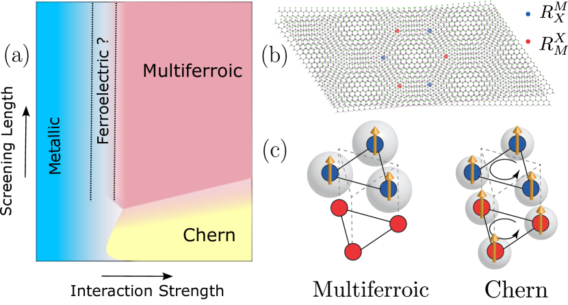
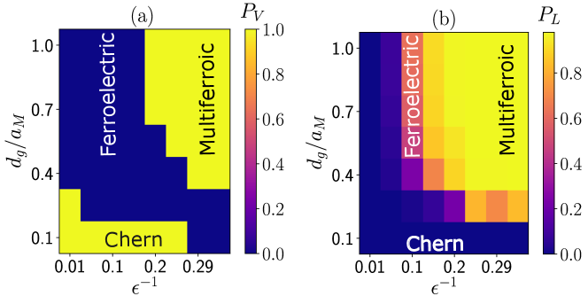
The key feature of the phase diagram at (Fig. 1(a)) is the robust presence of multiferroic order — ferromagnetism from spin-valley polarization and ferroelectricity from layer polarization, driven by long-range Coulomb repulsion.
We further demonstrate that shortening the range of the Coulomb interaction by tuning the gate-distance drives the system through a topological phase transition from the multiferroic phase to a ferromagnetic Chern insulator.
We provide an intuitive understanding of the competition between the two phases via a simple real space description of the topological flat bands.
We conclude with a discussion of experimental probes that may be used to detect the multiferroic phase.
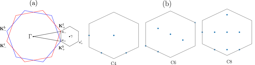
Model. Our starting point is continuum models Wu et al. (2019); Pan et al. (2020) developed for the valence bands of twisted TMD homobilayers. We are particularly interested in the regime where the active bands are topologically non-trivial and carry opposite Chern numbers in a given valley, together with their time-reversed partners in the opposite valley. To be specific, we focus on where this regime is accessible at twist angles Wu et al. (2019) as shown in Fig. 2(a), although we emphasize that our results apply more generally to other twisted TMD homobilayers such as twisted Pan et al. (2020) or when the low-lying energy bands admit a specific real space description as we elaborate below. The strong spin-orbit coupling in TMD valence bands Zhu et al. (2011) leads to an effective spin-valley locking where the spin up (down) is tied to valley ().
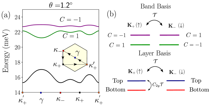
The active pair of bands in each valley are very close in energy while there is a much bigger gap to the remaining valence bands (Fig. 2(a)). Therefore we project interactions sup to the active bands, leading to the following Hamiltonian:
| (1) |
where denotes the top (bottom) band and denotes the valley (equivalently the spin because of the effective spin-valley locking). are hole band creation operators, and is the non-interacting band dispersion. The second term represents density-density interactions between the holes with the projected density operator in one valley given by where are the form factors calculated from the Bloch eigenstates of the bands. denotes the number of moiré unit cells. We model the interaction as the dual-gated Coulomb repulsion: with is the moiré lattice constant. The screening length represents the distance between the gates and the moiré superlattice and is the strength of interaction defined as with being the dielectric constant. The Hamiltonian (1) is normal ordered with respect to charge neutrality. In addition, it has the following key symmetries: a -rotation about an in-plane axis — that swaps the two layers, time reversal symmetry that flips the spin-valley degree of freedom, and symmetry corresponding to independent charge conservation within each valley.
For the purpose of diagnosing the possible competing phases, it is useful construct a maximally layer-polarized bases for the flat bands. To this end, we follow Ref. Devakul et al., 2021 and define , where is a unitary matrix that is optimized to maximize the layer polarization in each valley. The layer basis vectors within a single valley are related to each other by a combined symmetry (c.f. Fig.2(b)), thus spontaneous ferroelectric order can be conveniently detected numerically through breaking in the ground state.
Results. We perform an unbiased momentum space exact diagonalization (ED) study sup of the Hamiltonian (1) focusing on odd integer filling (one hole per moiré unit cell) and (three holes per moiré unit cell) sup . To characterize the obtained many-body ground states, we define the following two observables:
| (2) | |||
where is the band occupation, is the layer occupation and is the number of electrons in the finite system. The quantities in Eq. (2) probe distinct properties of the many-body ground state. measures spin-valley polarization and is sensitive to time-reversal symmetry breaking (ferromagnetism), while measures layer polarization and therefore contains information about the ferroelectricity in the system. Simultaneous non-zero values for both and thus indicate multiferroic order.
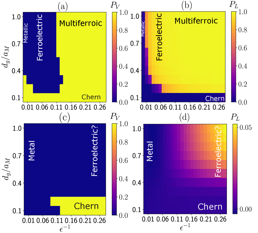
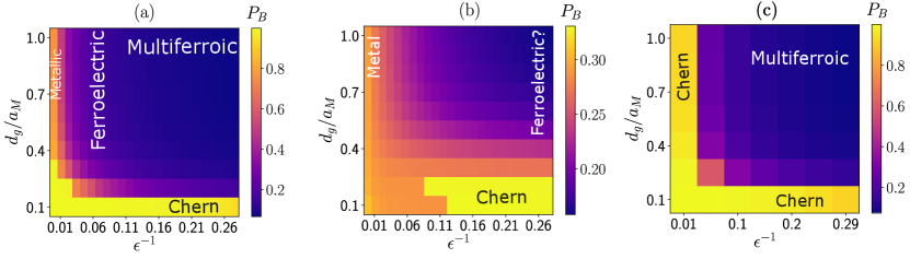
In Figs. 3(a) and 3(b), we present the phase diagram at filling as a function of two experimentally tunable parameters: (i) the ratio of the screening length of the dual-gated Coulomb interaction to the moiré lattice constant and (ii) the inverse of the dielectric constant . When is extremely small, we find the expected metallic phase. The metallic phase has no spin-valley polarization (c.f Fig. 3 (a)) and the many-body ground state occupation is found to be concentrated in the lower band in each valley, indicating that the system simply minimizes the non-interacting kinetic energy in this regime. As is increased, we find ubiquitous ferromagnetic order due to spin-valley polarization, as evident in figure 3(a). The spin-valley ferromagnetism is of the Ising type and corresponds to spontaneous symmetry breaking of time-reversal symmetry. In addition to ferromagnetism, we find the ground state in the majority of the phase diagram to show strong layer polarization, i.e, ferroelectricity, by spontaneously breaking the symmetry. To characterize this, we compute the layer polarization defined in Eq. (2) and find that it is non-zero, as shown in figure 3(b). The simultaneous occurence of spin-valley ferromagnetism and ferroelectricity corresponds to the multiferroic phase which is observed for approximately and .
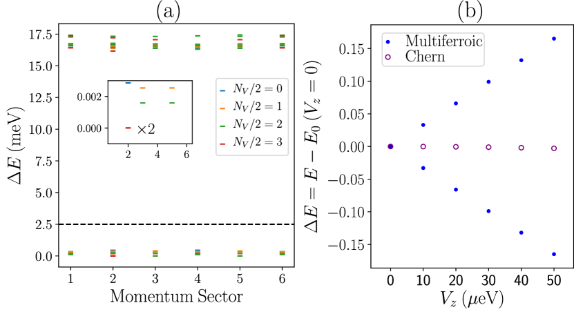
Further evidence that the layer-swapping symmetry is broken in the multiferroic phase may be gleaned from the response of the ground states to a symmetry breaking perturbation in the form of a tiny out of plane displacement field . When , the many-body multiferroic ground state manifold is two-fold degenerate (see inset of Fig. 4(a)) if we fix spin-valley polarization. The two degenerate states are related by , and correspond to larger carrier density in the top or bottom layer. The displacement field is odd under , and therefore splits this degeneracy. Accordingly, as we increase , we find the two-fold degenerate ground states of the multiferroic phase split linearly in and flow in opposite directions as shown in Fig. 4(b) — providing comprehensive evidence of breaking. This behavior of the multiferroic ground state manifold stands in sharp contrast to the ground states of the competing Chern insulator phase, that is insensitive to small displacement fields. Lastly, we note that the parts of the phase diagram where we observe layer polarization also exhibit significantly large off-diagonal components in the band basis sup . This is consistent with our intuition that the layer bases - an approximate eigenbasis for the multiferroic - strongly mix the top and bottom bands. Indeed, such band-mixing is expected for large values of where multiferroicity is observed — interactions overcome the small band gap between the two active bands.
Upon decreasing the screening length , the range of Coulomb interaction is shortened in real space and we observe a transition to a Chern insulator phase obtained by hole filling one of the upper Chern band within one valley at . While the Chern insulator is still ferromagnetic in both orbital (valley) and spin sectors, as indicated in Fig. 3(a), the ferroelectricity disappears as the Chern bands themselves have almost equal spectral weight in both layers.
In addition to the fully symmetric metal, spin-valley polarized Chern insulator and multiferroic phases, we also find signatures of an intermediate ferroelectric phase — characterized by non-zero layer polarization and vanishing valley polarization, between the metallic and the multiferroic phases. In contrast to the rest of the phases, we find the existence of this intermediate ferroelectric phase at to be sensitive to the choice of the momentum space cluster used for ED sup . Henceforth, we focus on understanding the rest of the phase diagram, which is robust to the choice of momentum cluster.
The observed structure of the phase diagram in Fig 3(a-b) for , in particular the competition between the Chern insulator and the multiferroic, can be understood from an approximate real space description of the flat bands. The layer-projected wavefunctions of the two active bands in each spin-valley sector are found Wu et al. (2019); Pan et al. (2020) to be localized on atomic sites that form a triangular lattice in each layer (Fig. 1(b)). In the top layer, these atomic sites are denoted by , as metal () atoms of the top layer are locally aligned with chalcogen () atoms of the bottom layer within the moiré unit cell. In the bottom layer, these sites are denoted by , as the chalcogen () atoms of the top layer are locally aligned with the metal () atoms of the bottom layer. Taken together, the two inter-penetrating triangular lattices from the two layers form a honeycomb lattice at the moiré lengthscale.
This lattice structure combined with the opposite Chern bands allows the construction of a tight-binding model that provides a realization of Kane-Mele physics Kane and Mele (2005) at the non-interacting level. Since states in the two layers are localized on the two sublattices and , layer polarization implies sublattice polarization. The reason for sublattice polarization for long-range repulsion is quite intuitive. For large screening lengths , the interaction is essentially long range — there is significant nearest-neighbor repulsion between the electrons in addition to on-site repulsion. In this regime, the electrons can minimize both on-site and nearest neighbor repulsive interactions by localizing on a single triangular sublattice of the effective honeycomb lattice (Fig. 1(c)), leading to ferroelectric order.
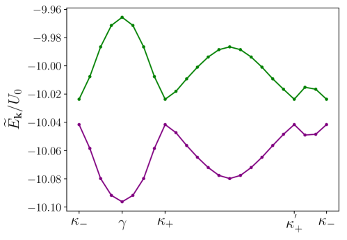
The aforementioned real space picture is strongly reflected in the many-body spectrum of the multiferroic phase shown in Fig. 4(a) where we observe a low energy manifold of states separated by a large gap from the rest of the spectrum. The number of the low-lying states in this manifold is always consistent with the expected dimension of a Hilbert space that is the sum of two subspaces, one for each sublattice. Each subspace consist of states with single hole occupancy for .
On the other hand, decreasing the screening length so that the range of the Coulomb interaction is much smaller than the distance between the sublattices implies that only the on-site (Hubbard) repulsion is important. In this regime, phases with uniform electron density on both sublattices, such as the Chern insulator, become energetically favorable, as observed in our numerics.
A few comments are in order. While we focused on twisted TMD homobilayers, our intuitive understanding of our numerical results that are based on the full continuum model, in terms of a simple real space picture consisting of layers as sublattices on a honeycomb lattice, suggests that multiferroicity could be looked for in models that admit such interpretation. This expands the scope of our study to other TMD moiré systems such as TMD heterobilayers where the moiré potential extrema could effectively give to a honeycomb lattice description Devakul and Fu (2022); Zhang et al. (2020, 2021); Slagle and Fu (2020). This alleviates the need for manufacturing samples with tiny twist angles, a challenge so far in experiments on TMD heterostructures.
Our results highlight a screening-dependent competition between the quantum anomalous Hall effect and multiferroicity that could be tuned in experiments by changing electrostatic gate distances. Based on our observation that the Chern insulator phase requires small gate distances , we expect multiferroicity to be the dominant phase at filling when the band gap between the active flat bands is minimal. Further, the multiferroic insulator breaks only discrete symmetries and , and is therefore robust to thermal fluctuations. Enhancing the gap between the active bands by increasing the twist angle improves the likelihood of stabilizing a Chern insulator without the need of very small screening lengths.
The moiré superlattice plays a crucial role in the energetic stabilization of ferroelectricity, as it endows the effective honeycomb lattice with a moiré lengthscale that is much larger than the microscopic inter-layer spacing at small twist angles. In absence of the moiré potential, two adjacent sites belonging to the same sublattice (layer) would typically be much closer in real space, relative to two sites in different sublattices (layers). Accordingly, the Coulomb repulsion between electrons at adjacent sites in the same layer would dominate inter-layer repulsion, and sublattice/layer polarization would be energetically penalized, thereby precluding ferroelectric order.
We note that multiferroicity in twisted TMDs has been suggested in Ref. Haavisto et al., 2022 based on a mean-field study of a simplified nearest neighbour hopping model on honeycomb lattice. However, such a model cannot accurately capture the topology of the underlying bands, or the detailed structure of the form-factors (Bloch wavefunction overlaps) that have proven to be crucial in understanding the phase diagram of moiré systems Bultinck et al. (2020); Bernevig et al. (2021); Lian et al. (2021). Our study uses a realistic continuum model that has the advantage of accurately capturing the band topology and form-factors. This enables us to study the energetic competition between the multiferroic and other phases with non-trivial topology, such as the Chern insulator.
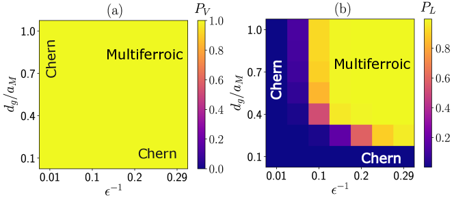
Our results are robust to the effects of band mixing with the third valence band (c.f. Fig. 2 (a)). We find that the phase diagram, especially the extent of the multiferroic phase, to be qualitatively similar upon including three bands per valley in the ED calculation, thereby justifying projecting the interactions to two bands per valley sup . Analogously, the phase diagram obtained via ED on a disinct cluster in momentum space (C8) is similar, and exhibits robust multiferroic order at larger interaction range sup . On the other hand, the multiferroic phase does not appear in the phase diagram (Figs. 3(c) and 3(d)) at filling , corresponding to hole-filling of three of the four bands, as the layer-polarized ferroelectric phase is valley-unpolarized in the parameter regime we studied, in contrast to . Since the interacting Hamiltonians at and are identical up to single-particle terms after a particle-hole transformation, we ascribe the lack of strong correlation effects at to an interaction-induced enhancement of bandwidth, as illustrated explicitly in the supplement sup .
Finally, we note that the bare band-structure — a pair of flat bands with contrasting Chern numbers in each valley as shown in Fig. 2 — is deceptively similar to the spinless chiral limit of magic angle twisted bilayer graphene (MATBG) Tarnopolsky et al. (2019). However, the interacting phase diagram of moiré TMD homobilayers that we found here is quite different from MATBG in the strong coupling limit Bultinck et al. (2020); Bernevig et al. (2021); Lian et al. (2021). We attribute this to crucial symmetry differences between the two systems. MATBG has enhanced symmetry that prevents the construction of localized Wannier orbitals for the bands in each valley, but admits a Chern basis where the interactions are diagonal in the chiral limit Song et al. (2019); Zou et al. (2018); Po et al. (2019, 2018). In contrast, the strong spin-orbit coupling in moiré TMDs reduces the symmetry, which allows for the possibility to construct localized Wannier orbitals to describe the flat bands in each valley, but makes the interaction strongly off-diagonal in the band (Chern) basis.
Conclusion. In this paper, we have presented a comprehensive study of the phase diagram of twisted TMD homobilayers in the presence of long range Coulomb interactions. Our main finding is the abundance of multiferroicity driven by spontaneous symmetry breaking and strong interactions through large parts of the phase diagram therefore making twisted TMDs a promising candidate for designing multiferroics with coexisting magnetic and electric order with prospects of useful technological applications Eerenstein et al. (2006); Parsonnet et al. (2022); Manipatruni et al. (2019); Chen and Sigrist (2015).
Experimentally, the multiferroic phase can be identified via a combination of probes. Spin-polarized scanning tunneling microscopy (SP-STM) Bode (2003) can detect spin-polarization, while simultaneously inferring the lack of orbital magnetization (characteristic of the Chern insulator) via a scanning Squid probe José Martínez-Pérez and Koelle (2017). The electrical polarization can be probed via nanoscale electrometry Dolde et al. (2011); Block et al. (2021); Bian et al. (2021); Sahay et al. (2021) using optically active color centers in solids, such as boron vacancy (V) centers in hexagonal boron nitride substrate Vaidya et al. (2023) that are sensitive to local electric fields. Such color centers can also be used as nanoscale probes of ferromagnetism Casola et al. (2018); Hong et al. (2013); Chatterjee et al. (2019), present in both multiferroic and Chern phases.
Having established the prospects of multiferroicity in twisted TMDs homobilayers, a natural future direction is to explore possible ways to manipulate the magnetic order with applied electric fields and vice versa. While electrical control of orbital magnetism has been proposed and demonstrated experimentally in graphene-based moiré systems Lu et al. (2019); Polshyn et al. (2020), the presence of strong spin-orbit coupling in TMDs can offer additional routes to achieve a higher degree of tunability.
Finally, while we have focused on interacting physics at odd-integer fillings of flat bands, where multiferroicity is more likely to appear, we anticipate interesting correlated physics to show up at half-filling (). Specifically, we expect different magnetically ordered phases and possible quantum spin liquids competing with the quantum spin-Hall phase obtained in the non-interacting limit. In addition, exotic phases such as fractional Chern insulators with intrinsic topological order Li et al. (2021c), or skyrmion-pairing superconductivity Grover and Senthil (2008); Chatterjee et al. (2020); Khalaf et al. (2021); Wang et al. (2021); Chatterjee et al. (2022); Kwan et al. (2022) may show up at fractional fillings of the flat bands. We leave the study of the full interacting phase diagram as a function of doping to future work.
Acknowledgements.
Acknowledgements. We are grateful to Vladimir Calvera, Johan Carlström, Valentin Crépel, Liang Fu, Sid Morampudi, Dan Parker and Taige Wang for helpful discussions. A.A and E.J.B are supported by the Swedish Research Council (grant 2018-00313), and the Knut and Alice Wallenberg Foundation (KAW) via the Wallenberg Academy Fellows program (2018.0460). S.C. acknowledges support from the U.S. DOE, Office of Science, Office of Advanced Scientific Computing Research, under the Accelerated Research in Quantum Computing (ARQC) program and the ARO through the MURI program (grant number W911NF-17-1-0323).References
- Geim and Grigorieva (2013) A. K. Geim and I. V. Grigorieva, “Van der Waals heterostructures,” Nature 499, 419–425 (2013).
- Lado and Liljeroth (2021) J. L. Lado and P. Liljeroth, “Designer quantum matter in van der Waals heterostructures,” (2021), arXiv:2102.11779 [cond-mat] .
- Balents et al. (2020) L. Balents, C. R. Dean, D. K. Efetov, and A. F. Young, “Superconductivity and strong correlations in moiré flat bands,” Nat. Phys. 16, 725–733 (2020).
- Cao et al. (2018a) Y. Cao, V. Fatemi, A. Demir, S. Fang, S. L. Tomarken, J. Y. Luo, J. D. Sanchez-Yamagishi, K. Watanabe, T. Taniguchi, E. Kaxiras, R. C. Ashoori, and P. Jarillo-Herrero, “Correlated insulator behaviour at half-filling in magic-angle graphene superlattices,” Nature 556, 80–84 (2018a).
- Cao et al. (2018b) Y. Cao, V. Fatemi, S. Fang, K. Watanabe, T. Taniguchi, E. Kaxiras, and P. Jarillo-Herrero, “Unconventional superconductivity in magic-angle graphene superlattices,” Nature 556, 43–50 (2018b).
- Chen et al. (2019) G. Chen, A. L. Sharpe, P. Gallagher, I. T. Rosen, E. J. Fox, L. Jiang, B. Lyu, H. Li, K. Watanabe, T. Taniguchi, J. Jung, Z. Shi, D. Goldhaber-Gordon, Y. Zhang, and F. Wang, “Signatures of tunable superconductivity in a trilayer graphene moiré superlattice,” Nature 572, 215–219 (2019).
- Lu et al. (2019) X. Lu, P. Stepanov, W. Yang, M. Xie, M. A. Aamir, I. Das, C. Urgell, K. Watanabe, T. Taniguchi, G. Zhang, A. Bachtold, A. H. MacDonald, and D. K. Efetov, “Superconductors, orbital magnets and correlated states in magic-angle bilayer graphene,” Nature 574, 653–657 (2019).
- Yankowitz et al. (2019) M. Yankowitz, S. Chen, H. Polshyn, Y. Zhang, K. Watanabe, T. Taniguchi, D. Graf, A. F. Young, and C. R. Dean, “Tuning superconductivity in twisted bilayer graphene,” Science 363, 1059–1064 (2019).
- Tang et al. (2020) Y. Tang, L. Li, T. Li, Y. Xu, S. Liu, K. Barmak, K. Watanabe, T. Taniguchi, A. H. MacDonald, J. Shan, and K. F. Mak, “Simulation of Hubbard model physics in WSe2/WS2 moiré superlattices,” Nature 579, 353–358 (2020).
- Xu et al. (2022) Y. Xu, K. Kang, K. Watanabe, T. Taniguchi, K. F. Mak, and J. Shan, “A tunable bilayer Hubbard model in twisted WSe2,” Nat. Nanotechnol. 17, 934–939 (2022).
- Wang et al. (2020) L. Wang, E.-M. Shih, A. Ghiotto, L. Xian, D. A. Rhodes, C. Tan, M. Claassen, D. M. Kennes, Y. Bai, B. Kim, K. Watanabe, T. Taniguchi, X. Zhu, J. Hone, A. Rubio, A. N. Pasupathy, and C. R. Dean, “Correlated electronic phases in twisted bilayer transition metal dichalcogenides,” Nat. Mater. 19, 861–866 (2020).
- Xu et al. (2020) Y. Xu, S. Liu, D. A. Rhodes, K. Watanabe, T. Taniguchi, J. Hone, V. Elser, K. F. Mak, and J. Shan, “Correlated insulating states at fractional fillings of moiré superlattices,” Nature 587, 214–218 (2020).
- Huang et al. (2021) X. Huang, T. Wang, S. Miao, C. Wang, Z. Li, Z. Lian, T. Taniguchi, K. Watanabe, S. Okamoto, D. Xiao, S.-F. Shi, and Y.-T. Cui, “Correlated insulating states at fractional fillings of the WS2/WSe2 moiré lattice,” Nat. Phys. 17, 715–719 (2021).
- Regan et al. (2020) E. C. Regan, D. Wang, C. Jin, M. I. Bakti Utama, B. Gao, X. Wei, S. Zhao, W. Zhao, Z. Zhang, K. Yumigeta, M. Blei, J. D. Carlström, K. Watanabe, T. Taniguchi, S. Tongay, M. Crommie, A. Zettl, and F. Wang, “Mott and generalized Wigner crystal states in WSe2/WS2 moiré superlattices,” Nature 579, 359–363 (2020).
- Li et al. (2021a) T. Li, S. Jiang, L. Li, Y. Zhang, K. Kang, J. Zhu, K. Watanabe, T. Taniguchi, D. Chowdhury, L. Fu, J. Shan, and K. F. Mak, “Continuous Mott transition in semiconductor moiré superlattices,” Nature 597, 350–354 (2021a).
- Ghiotto et al. (2021) A. Ghiotto, E.-M. Shih, G. S. S. G. Pereira, D. A. Rhodes, B. Kim, J. Zang, A. J. Millis, K. Watanabe, T. Taniguchi, J. C. Hone, L. Wang, C. R. Dean, and A. N. Pasupathy, “Quantum criticality in twisted transition metal dichalcogenides,” Nature 597, 345–349 (2021).
- Li et al. (2021b) T. Li, S. Jiang, B. Shen, Y. Zhang, L. Li, Z. Tao, T. Devakul, K. Watanabe, T. Taniguchi, L. Fu, J. Shan, and K. F. Mak, “Quantum anomalous Hall effect from intertwined moiré bands,” Nature 600, 641–646 (2021b).
- Zhao et al. (2022) W. Zhao, K. Kang, L. Li, C. Tschirhart, E. Redekop, K. Watanabe, T. Taniguchi, A. Young, J. Shan, and K. F. Mak, “Realization of the Haldane Chern insulator in a moir\’e lattice,” (2022), arXiv:2207.02312 [cond-mat] .
- Tao et al. (2022) Z. Tao, B. Shen, S. Jiang, T. Li, L. Li, L. Ma, W. Zhao, J. Hu, K. Pistunova, K. Watanabe, T. Taniguchi, T. F. Heinz, K. F. Mak, and J. Shan, “Valley-coherent quantum anomalous Hall state in AB-stacked MoTe2/WSe2 bilayers,” (2022), arXiv:2208.07452 [cond-mat] .
- Polshyn et al. (2020) H. Polshyn, J. Zhu, M. A. Kumar, Y. Zhang, F. Yang, C. L. Tschirhart, M. Serlin, K. Watanabe, T. Taniguchi, A. H. MacDonald, and A. F. Young, “Electrical switching of magnetic order in an orbital Chern insulator,” Nature 588, 66–70 (2020).
- Chen et al. (2020) G. Chen, A. L. Sharpe, E. J. Fox, Y.-H. Zhang, S. Wang, L. Jiang, B. Lyu, H. Li, K. Watanabe, T. Taniguchi, Z. Shi, T. Senthil, D. Goldhaber-Gordon, Y. Zhang, and F. Wang, “Tunable correlated Chern insulator and ferromagnetism in a moiré superlattice,” Nature 579, 56–61 (2020).
- Chen et al. (2022) G. Chen, A. L. Sharpe, E. J. Fox, S. Wang, B. Lyu, L. Jiang, H. Li, K. Watanabe, T. Taniguchi, M. F. Crommie, M. A. Kastner, Z. Shi, D. Goldhaber-Gordon, Y. Zhang, and F. Wang, “Tunable Orbital Ferromagnetism at Noninteger Filling of a Moiré Superlattice,” Nano Lett. 22, 238–245 (2022).
- Wang et al. (2022) X. Wang, C. Xiao, H. Park, J. Zhu, C. Wang, T. Taniguchi, K. Watanabe, J. Yan, D. Xiao, D. R. Gamelin, W. Yao, and X. Xu, “Light-induced ferromagnetism in moiré superlattices,” Nature 604, 468–473 (2022).
- Lin et al. (2022) J.-X. Lin, Y.-H. Zhang, E. Morissette, Z. Wang, S. Liu, D. Rhodes, K. Watanabe, T. Taniguchi, J. Hone, and J. I. A. Li, “Spin-orbit–driven ferromagnetism at half moiré filling in magic-angle twisted bilayer graphene,” Science 375, 437–441 (2022).
- Sharpe et al. (2019) A. L. Sharpe, E. J. Fox, A. W. Barnard, J. Finney, K. Watanabe, T. Taniguchi, M. A. Kastner, and D. Goldhaber-Gordon, “Emergent ferromagnetism near three-quarters filling in twisted bilayer graphene,” Science 365, 605–608 (2019).
- Liu and Dai (2021) J. Liu and X. Dai, “Orbital magnetic states in moiré graphene systems,” Nat Rev Phys 3, 367–382 (2021).
- Serlin et al. (2020) M. Serlin, C. L. Tschirhart, H. Polshyn, Y. Zhang, J. Zhu, K. Watanabe, T. Taniguchi, L. Balents, and A. F. Young, “Intrinsic quantized anomalous Hall effect in a moiré heterostructure,” Science 367, 900–903 (2020).
- Polshyn et al. (2022) H. Polshyn, Y. Zhang, M. A. Kumar, T. Soejima, P. Ledwith, K. Watanabe, T. Taniguchi, A. Vishwanath, M. P. Zaletel, and A. F. Young, “Topological charge density waves at half-integer filling of a moiré superlattice,” Nat. Phys. 18, 42–47 (2022).
- Eerenstein et al. (2006) W. Eerenstein, N. D. Mathur, and J. F. Scott, “Multiferroic and magnetoelectric materials,” Nature 442, 759–765 (2006).
- Parsonnet et al. (2022) E. Parsonnet, L. Caretta, V. Nagarajan, H. Zhang, H. Taghinejad, P. Behera, X. Huang, P. Kavle, A. Fernandez, D. Nikonov, H. Li, I. Young, J. Analytis, and R. Ramesh, “Nonvolatile Electric Field Control of Thermal Magnons in the Absence of an Applied Magnetic Field,” Phys. Rev. Lett. 129, 087601 (2022).
- Manipatruni et al. (2019) S. Manipatruni, D. E. Nikonov, C.-C. Lin, T. A. Gosavi, H. Liu, B. Prasad, Y.-L. Huang, E. Bonturim, R. Ramesh, and I. A. Young, “Scalable energy-efficient magnetoelectric spin–orbit logic,” Nature 565, 35–42 (2019).
- Chen and Sigrist (2015) W. Chen and M. Sigrist, “Dissipationless Multiferroic Magnonics,” Phys. Rev. Lett. 114, 157203 (2015).
- Wu et al. (2019) F. Wu, T. Lovorn, E. Tutuc, I. Martin, and A. H. MacDonald, “Topological Insulators in Twisted Transition Metal Dichalcogenide Homobilayers,” Phys. Rev. Lett. 122, 086402 (2019).
- Pan et al. (2020) H. Pan, F. Wu, and S. Das Sarma, “Band topology, Hubbard model, Heisenberg model, and Dzyaloshinskii-Moriya interaction in twisted bilayer ${\mathrm{WSe}}_{2}$,” Phys. Rev. Research 2, 033087 (2020).
- Zhu et al. (2011) Z. Y. Zhu, Y. C. Cheng, and U. Schwingenschlögl, “Giant spin-orbit-induced spin splitting in two-dimensional transition-metal dichalcogenide semiconductors,” Phys. Rev. B 84, 153402 (2011).
- (36) See Supplemental Material which contains Refs Varney et al., 2010; Shao et al., 2021 for model details and symmetries, additional results and comments on the exact diagonalization.
- Devakul et al. (2021) T. Devakul, V. Crépel, Y. Zhang, and L. Fu, “Magic in twisted transition metal dichalcogenide bilayers,” Nat Commun 12, 6730 (2021), arXiv:2106.11954 .
- (38) The calculations for are performed with a tiny displacement field to enforce the layer symmetry breaking since the Hamiltonian (1) is symmetric.
- Kane and Mele (2005) C. L. Kane and E. J. Mele, “Quantum Spin Hall Effect in Graphene,” Phys. Rev. Lett. 95, 226801 (2005).
- Devakul and Fu (2022) T. Devakul and L. Fu, “Quantum Anomalous Hall Effect from Inverted Charge Transfer Gap,” Phys. Rev. X 12, 021031 (2022).
- Zhang et al. (2020) Y. Zhang, N. F. Q. Yuan, and L. Fu, “Moir\’e quantum chemistry: Charge transfer in transition metal dichalcogenide superlattices,” Phys. Rev. B 102, 201115 (2020).
- Zhang et al. (2021) Y. Zhang, T. Liu, and L. Fu, “Electronic structures, charge transfer, and charge order in twisted transition metal dichalcogenide bilayers,” Phys. Rev. B 103, 155142 (2021).
- Slagle and Fu (2020) K. Slagle and L. Fu, “Charge transfer excitations, pair density waves, and superconductivity in moir\’e materials,” Phys. Rev. B 102, 235423 (2020).
- Haavisto et al. (2022) M. Haavisto, J. L. Lado, and A. O. Fumega, “Topological multiferroic order in twisted transition metal dichalcogenide bilayers,” SciPost Phys. 13, 052 (2022), arXiv:2204.03360 [cond-mat] .
- Bultinck et al. (2020) N. Bultinck, E. Khalaf, S. Liu, S. Chatterjee, A. Vishwanath, and M. P. Zaletel, “Ground State and Hidden Symmetry of Magic-Angle Graphene at Even Integer Filling,” Phys. Rev. X 10, 031034 (2020).
- Bernevig et al. (2021) B. A. Bernevig, Z.-D. Song, N. Regnault, and B. Lian, “Twisted bilayer graphene. III. Interacting Hamiltonian and exact symmetries,” Phys. Rev. B 103, 205413 (2021).
- Lian et al. (2021) B. Lian, Z.-D. Song, N. Regnault, D. K. Efetov, A. Yazdani, and B. A. Bernevig, “Twisted bilayer graphene. IV. Exact insulator ground states and phase diagram,” Phys. Rev. B 103, 205414 (2021).
- Tarnopolsky et al. (2019) G. Tarnopolsky, A. J. Kruchkov, and A. Vishwanath, “Origin of Magic Angles in Twisted Bilayer Graphene,” Phys. Rev. Lett. 122, 106405 (2019).
- Song et al. (2019) Z. Song, Z. Wang, W. Shi, G. Li, C. Fang, and B. A. Bernevig, “All Magic Angles in Twisted Bilayer Graphene are Topological,” Phys. Rev. Lett. 123, 036401 (2019).
- Zou et al. (2018) L. Zou, H. C. Po, A. Vishwanath, and T. Senthil, “Band structure of twisted bilayer graphene: Emergent symmetries, commensurate approximants, and Wannier obstructions,” Phys. Rev. B 98, 085435 (2018).
- Po et al. (2019) H. C. Po, L. Zou, T. Senthil, and A. Vishwanath, “Faithful tight-binding models and fragile topology of magic-angle bilayer graphene,” Phys. Rev. B 99, 195455 (2019).
- Po et al. (2018) H. C. Po, H. Watanabe, and A. Vishwanath, “Fragile Topology and Wannier Obstructions,” Phys. Rev. Lett. 121, 126402 (2018).
- Bode (2003) M. Bode, “Spin-polarized scanning tunnelling microscopy,” Reports on Progress in Physics 66, 523 (2003).
- José Martínez-Pérez and Koelle (2017) M. José Martínez-Pérez and D. Koelle, “Nanosquids: Basics & recent advances,” Physical Sciences Reviews 2, 20175001 (2017).
- Dolde et al. (2011) F. Dolde, H. Fedder, M. W. Doherty, T. Nöbauer, F. Rempp, G. Balasubramanian, T. Wolf, F. Reinhard, L. C. Hollenberg, F. Jelezko, et al., “Electric-field sensing using single diamond spins,” Nature Physics 7, 459–463 (2011).
- Block et al. (2021) M. Block, B. Kobrin, A. Jarmola, S. Hsieh, C. Zu, N. Figueroa, V. Acosta, J. Minguzzi, J. Maze, D. Budker, and N. Yao, “Optically enhanced electric field sensing using nitrogen-vacancy ensembles,” Phys. Rev. Appl. 16, 024024 (2021).
- Bian et al. (2021) K. Bian, W. Zheng, X. Zeng, X. Chen, R. Stöhr, A. Denisenko, S. Yang, J. Wrachtrup, and Y. Jiang, “Nanoscale electric-field imaging based on a quantum sensor and its charge-state control under ambient condition,” Nature Communications 12, 2457 (2021).
- Sahay et al. (2021) R. Sahay, S. Hsieh, E. Parsonnet, L. W. Martin, R. Ramesh, N. Y. Yao, and S. Chatterjee, “Noise Electrometry of Polar and Dielectric Materials,” arXiv e-prints , arXiv:2111.09315 (2021), arXiv:2111.09315 [cond-mat.mtrl-sci] .
- Vaidya et al. (2023) S. Vaidya, X. Gao, S. Dikshit, I. Aharonovich, and T. Li, “Quantum sensing and imaging with spin defects in hexagonal boron nitride,” Advances in Physics X 8, 2206049 (2023), arXiv:2302.11169 [quant-ph] .
- Casola et al. (2018) F. Casola, T. Van Der Sar, and A. Yacoby, “Probing condensed matter physics with magnetometry based on nitrogen-vacancy centres in diamond,” Nature Reviews Materials 3, 1–13 (2018).
- Hong et al. (2013) S. Hong, M. S. Grinolds, L. M. Pham, D. Le Sage, L. Luan, R. L. Walsworth, and A. Yacoby, “Nanoscale magnetometry with nv centers in diamond,” MRS bulletin 38, 155–161 (2013).
- Chatterjee et al. (2019) S. Chatterjee, J. F. Rodriguez-Nieva, and E. Demler, “Diagnosing phases of magnetic insulators via noise magnetometry with spin qubits,” Phys. Rev. B 99, 104425 (2019).
- Li et al. (2021c) H. Li, U. Kumar, K. Sun, and S.-Z. Lin, “Spontaneous fractional Chern insulators in transition metal dichalcogenide moiré superlattices,” Phys. Rev. Research 3, L032070 (2021c).
- Grover and Senthil (2008) T. Grover and T. Senthil, “Topological spin hall states, charged skyrmions, and superconductivity in two dimensions,” Phys. Rev. Lett. 100, 156804 (2008).
- Chatterjee et al. (2020) S. Chatterjee, N. Bultinck, and M. P. Zaletel, “Symmetry breaking and skyrmionic transport in twisted bilayer graphene,” Phys. Rev. B 101, 165141 (2020).
- Khalaf et al. (2021) E. Khalaf, S. Chatterjee, N. Bultinck, M. P. Zaletel, and A. Vishwanath, “Charged skyrmions and topological origin of superconductivity in magic-angle graphene,” Science Advances 7, eabf5299 (2021), arXiv:2004.00638 [cond-mat.str-el] .
- Wang et al. (2021) Z. Wang, Y. Liu, T. Sato, M. Hohenadler, C. Wang, W. Guo, and F. F. Assaad, “Doping-induced quantum spin hall insulator to superconductor transition,” Phys. Rev. Lett. 126, 205701 (2021).
- Chatterjee et al. (2022) S. Chatterjee, M. Ippoliti, and M. P. Zaletel, “Skyrmion superconductivity: Dmrg evidence for a topological route to superconductivity,” Phys. Rev. B 106, 035421 (2022).
- Kwan et al. (2022) Y. H. Kwan, G. Wagner, N. Bultinck, S. H. Simon, and S. A. Parameswaran, “Skyrmions in twisted bilayer graphene: Stability, pairing, and crystallization,” Phys. Rev. X 12, 031020 (2022).
- Varney et al. (2010) C. N. Varney, K. Sun, M. Rigol, and V. Galitski, “Interaction effects and quantum phase transitions in topological insulators,” Phys. Rev. B 82, 115125 (2010).
- Shao et al. (2021) C. Shao, E. V. Castro, S. Hu, and R. Mondaini, “Interplay of local order and topology in the extended Haldane-Hubbard model,” Phys. Rev. B 103, 035125 (2021).
I Supplemental Material
In this supplemental material, we elaborate on the model presented in the main text, provide additional results and details regarding the methods used.
II Model
We are concerned with continuum models that describe twisted TMD homobilayers. The low energy physics in each layer comes from the spin-orbit split valence bands maxima around the corners of the Brillouin zone, the valley points. The construction of the continuum model follows from the approach introduced in Ref. Wu et al. (2019). The Hamiltonian around a single valley (say valley ) is given by
| (S1) |
where with is an operator that creates an electron with momentum around valley in layer . is the TMD monolayer low energy Hamiltonian around valley in layer . It’s modelled as a free quadratic dispersion, and where is the effective mass and are the corners of the moiré Brillouin zone around one valley as shown in Fig. S5(a). is an applied displacement field between the top and bottom layers. The matrix describes the moiré potential with with and is the lattice constant of the moiré superlattice.
| (S2) |
The matrix is constrained by the symmetry of the bilayer system to be and . The diagonal terms of represent the moiré potential in the same layer (top or bottom) while the off-diagonal terms represent interlayer hopping. Hamiltonians of the form (S1) have the following symmetries.
-
•
Moiré translation symmetry :
-
•
Time reversal symmetry that flips the two valleys :
-
•
Three-fold rotation :
-
•
In-plane reflection around the axis that flips the layers. This operation is defined with respect to the origin of the twist of the bilayer, that is the point in Fig. S5(a). In momentum space, this operation flips the valley also so : with and is Pauli in the layer space. Combining with time reversal symmetry flips back the valley so the combined action of is a single valley symmetry. : with
In the main text, we used twisted for our numerical simulations. It is modelled by the following parameters Wu et al. (2019). For twist angle , the moiré lattice constant is .
III Interaction Hamiltonian
As discussed in the main text, we focus on the top two flat bands in each valley. We project the long-range Coulomb interaction onto these set of bands. We consider interacting holes in the moiré valence bands. We define the hole operators . By diagonalizing the Hamiltonian (S1), they are given in terms of the band operators by
| (S3) |
where is the component of the Bloch wavefunctions for band in valley obtained in the plane-wave basis expansion . The density operator in one valley is given by
| (S4) |
where are the form factors calculated from the Bloch eigenstates of the bands. The projection to the top two bands corresponds to restricting the sum in equation (S4) to the top two bands and discarding the rest. We then consider density-density interactions defined as
| (S5) |
where denotes normal ordering with respect to charge neutrality (no holes in the system), is the number of moiré unit cells and is taken to be the dual-gated Coulomb interactions with is the moiré lattice constant. The screening length represents the distance between the gates and the moiré superlattice and is the strength of interaction. We have neglected intervalley interaction terms as they are much weaker, they scale roughly like where is the lattice constant of the monolayer system. The Hamiltonian (S5) has a symmetry corresponds to independent charge conservation within each valley. The way the dual-gated Coulomb potential is defined makes the constant corresponds to the bare Coulomb potential at a separation of one moiré lattice constant, with is the dielectric constant.
IV Three band ED at
In this section, we investigate the effects of band mixing with the third valence band at . We include the third band (in each valley) in our ED calculation and find qualitatively similar results to the two band per valley case presented in the main text. As shown in Figs. S1(a) and S1(b), we find the existence of the multiferroic phase for strong interaction strength values of as evident in the maximal valley polarization and layer polarization . The multiferroic phase competes with a ferroelectric phase and a Chern insulator phase as a function of the interaction strength and the interaction range .
V ED results on the C8 cluster for
In this section, we present results obtained from exact diagonalization on the C8 cluster (c.f Fig. S5(b)) at filling . On this cluster, we observe valley polarization in the whole parameter space studied as shown in Fig. S2(a). In the valley polarized space, we observe both a Chern insulator and a multiferroic phase as highlighted in Fig. S2(b). We notice a sharp transition betweeh the Chern insulator and the multiferroic phase on this cluster with no signs of intermediate ferroelectric phases.
VI Band Polarization
In the main text, we have defined the observables and in equation (2) to characterize the phase diagram. Here, we present results for another quantity, that measures the band polarization, i.e - the difference in occupations between the top and bottom bands. It contains information about the degree of band mixing. It’s defined as follow
| (S6) |
In Fig. S3, we show at fillings and . We notice that is very small in the multiferroic phase. This can be understood as a consequence of layer polarization which is off-diagonal in the band basis as discussed in the main text.
VII vs
In this section, we elaborate on the difference between filling and . As shown in the main text, there is an absence of spin-valley polarization (and multiferroicity) at filling compared to filling . Within our band-projected exact diagonalization, keeping two bands per valley, the Hamiltonians describing the two fillings are related by a particle-hole transformation. Quite generally, upon particle-hole transformation , the Hamiltonian in equation (1) will transform as
| (S7) | |||
The first term represents the non-interacting disperion. The third term represents the interactions between the particles. The second term represents an interaction-induced single particle term , it’s given explicitly by
| (S8) | |||
We are going to focus on the regime where interactions dominate over the non-interacting dispersion (multiferroicity persists in the strong interaction limit). Let be the particle-hole dual filling of . Filling corresponds to for the two-band per valley projected model. For filling , the Hamiltonian (S7) (without the non-interacting dispersion) has a similar form to the non particle-hole transformed Hamiltonian descriping except for the interaction-induced single particle terms (S8). At filling , there is robust multiferroicity for strong and long-range interaction but at filling (equivalently ), the spin-valley polarization vanishes. We postulate that such a difference can be attributed to the interaction-induced single particle terms (S8). The effective bandwidth that arises from these terms can destabilize the spin-valley ferromagnetism. In Fig. S4, we plot the band structure obtained from diagonalizing the interaction induced single particle terms (S8). We find the bandwidth of the top and bottom bands to be roughly and respectively where is the strength of the interaction. When meV (roughly ), this gives meV and meV. To compare, the non-interacting bandwidth at is given by meV and meV. We see that the interaction-induced dispersion can be greater than the non-interacting bandwidth. Since such a bandwidth depends on the strength of the interaction, this means that it cannot be overcome for stronger interactions.
VIII Exact Diagonalization
The main method we employ in this paper is exact diagonalization on finite clusters of the Hamiltonian (1) in the main text. We work directly in momentum space so the finite clusters used are grids in momentum space. In Fig. S5(b), we show the clusters that were used in generating and interpreting the results in the main text. Only cluster C6 that features both the points and the point which is the main reason why we choose this cluster to present the results in the main text as it contains the highest number of different symmetry points.
It is worth mentioning that we find general agreement among the results obtained from the different clusters, namely the robust existence of the phases, the metal, the multiferroic phase and the Chern insulator. We also note that we observe on cluster C6 signatures of an intermediate ferroelectric phase between the metal and the multiferrioic and similarily between the Chern insulator and the mutliferroic as discussed in the main text. The intermediate phase has zero spin-valley polarization with signs of breaking the symmetry and possible anti-ferromagnetic stripe correlations. However, the finite size limitations prevents us from pin-pointing if this phase exists or it is a finite-size artifact. On clusters C4 and C8, we observe the absence of such a phase. However clusters C4 and C8 don’t feature the point which could play an important role in choosing different phases Varney et al. (2010); Shao et al. (2021).