Plasma sheath studies using a physical treatment of electron emission from a dielectric wall
Abstract
When a plasma sheath forms next to a dielectric wall, material properties determine electron absorption and reflection from the surface, impacting the sheath formation and structure. The low energy regime of this interaction is often not considered rigorously in emissive sheath simulations, but may be modeled from quantum mechanical first principles, and has important applications to plasma thrusters and fusion devices. In this work, low energy electron reflection from the wall is implemented as a boundary condition in a continuum kinetic framework and the sheath is simulated for dielectric material parameters in high and low emission cases. The results presented here demonstrate that the material parameters can have significant effect on the resulting sheath profile and particle distribution functions. Surfaces with high reflection rates see the formation of a space-charge limited sheath.
I Introduction
As plasma interacts with an absorbing surface, the electrons have a higher mobility and impact the boundary at a quicker rate than the less mobile ions. The result of this is a barrier field allowing the wall to float at a negative potential, accelerating ions and retarding electrons. This positive space-charge region where the potential profile drops towards the wall is called the plasma sheath.Langmuir (1923); Riemann (1991); Robertson (2013) The sheath entrance is typically defined by the point where the Bohm sheath criterion is met;Bohm (1949) that is, where the ion velocity exceeds the Bohm speed
| (1) |
In this equation is the ionization state, is the electron temperature in eV, is the ion mass, and is the electron charge. It should be noted that this model is simplified, as it has been shown the sheath entrance cannot rigorously be defined as a single point.Tang and Guo (2016); Li et al. (2022) However, it is sufficient for the purposes of this work to think of the sheath entrance as occurring several Debye lengths from the wall, where
| (2) |
with being the permittivity of free space, and the electron density. This work builds on a previous examination of the classical plasma sheath using continuum kinetic simulations.Cagas et al. (2017)
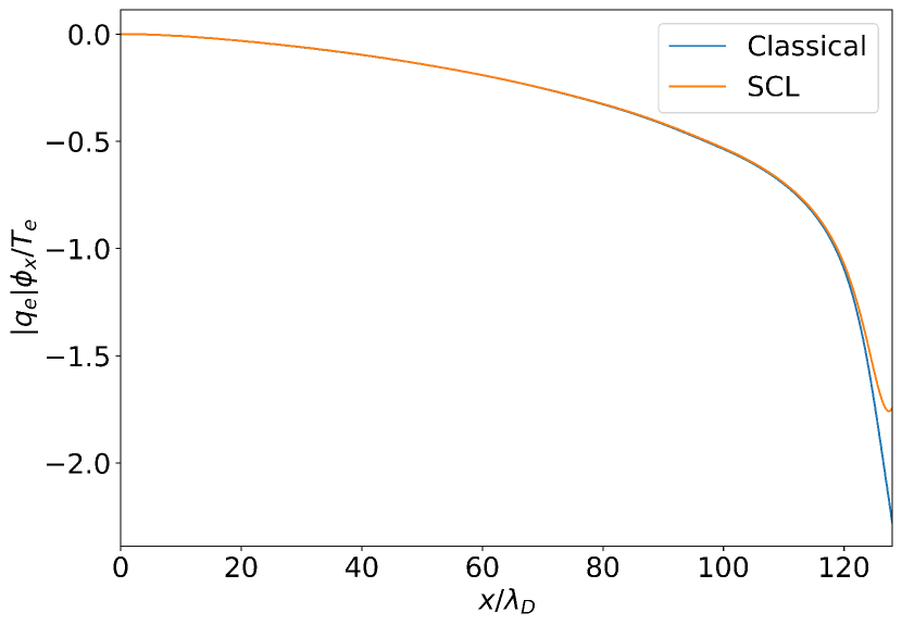
The surface interacting with the plasma will cause some electrons to be emitted back into the sheath instead of acting as a perfectly absorbing boundary. This emission is characterized by the electron flux gain , defined as the ratio of outward flux to inward flux at the wall. For lower values of , the sheath which forms is classical; that is, monotonic, with a negative wall potential relative to the plasma edge. At some critical gain , a non-monotonic space-charge limited (SCL) sheath forms for .Hobbs and Wesson (1967); Sheehan et al. (2014); Schwager (1993) The potential profiles of the classical and SCL solutions are displayed in Fig. 1. Finally, while less relevant for this work, for it has been shown that, if ion collision effects are accounted for, the sheath will transition to an inverse sheath where the wall potential is positive relative to the plasma edge.Campanell (2013); Campanell and Umansky (2016)
Numerous papers have examined the effect of strong electron emission on the sheath, however, previous works have typically treated the emitted electron population as a cold Maxwellian injection typical of thermionic probe emission.Sheehan et al. (2014); Campanell and Umansky (2016) In the case of emission from a material under electron impact, the relationship between the electron flux into the wall and the emitted population is more complicated. The work presented here shows the effects of implementing a physical treatment of emission as a boundary condition for simulations of the plasma sheath formed by interaction with a dielectric wall.
Emitted electrons are generally distinguished as falling in three primary categories.Jensen (2018) These are the true secondary electrons which are emitted directly from the material, rediffused electrons which enter the material and are eventually reemitted, and the elastically reflected electrons which fail to penetrate the material. At low energies, the reflected population dominates the other two and is the focus of this work. A number of approaches have been taken to model the emitted electron populations for specific materials, the most common of which focus on empirical or semi-empirical fits to beam emission data.Chung and Everhart (1974); Scholtz, Dijkkamp, and Schmitz (1996); Furman and Pivi (2002) While these approaches work extremely well in high-energy regimes, a general lack of extensive low-energy emission data means the models must typically be extrapolated to the low energy regime (). For many plasma applications relevant to the plasma sheath, however, such as in Hall thrustersDunaevsky, Raitses, and Fisch (2003) and magnetic confinement fusion devices,Stangeby and McCracken (1990) a large portion of the plasma in contact with the wall is in the low energy regime. Thus, the quantum mechanical derivation of the reflection function for dielectric materials by Bronold and FehskeBronold and Fehske (2015) is preferred for this work due to its first principles approach to lower energy plasma material interaction. While both the backscattering and rediffusion of particles are considered by Bronold and Fehske, as the rediffusion term is both less physically significant and more computationally expensive to implement than reflection, it is not considered within the scope of this paper.
II Numerical model and problem setup
II.1 Numerical model
Kinetic theory of plasmas describes the evolution of the distribution functions for the particle species through the Vlasov-Maxwell-Fokker-Planck (VM-FP) system of equations. The core of this system is the Boltzmann equation
| (3) |
which describes the behavior of the distribution in time, with Maxwell’s equations evolving the electromagnetic fields. Here, is the particle distribution function for species , is a source injection term, and is a collision term.
The term representing Coulomb collision effects is modeled by a Lenard-BernsteinDougherty (1964) (LBO, known also as a Dougherty operator) collision operator. This operator takes the form
| (4) |
where there is a summation over each species being collided with. These terms are dependent on the primitive moments and , representing the cross flow velocity and thermal speed, respectively. No collisional effects outside of Coulomb collisions are considered within the scope of this work. Also, it should be noted that wall sputtering, interaction with neutral species, and ionization effects all lie outside the present scope of this work, but are important sheath phenomenon with potentially wide ramifications for emissive sheath behavior.
The discontinuous GalerkinCockburn and Shu (2001) (DG) method yields the full discretized system of equationsHakim, Hammett, and Shi (2014); Juno et al. (2018); Juno (2020); Hakim and Juno (2020); Hakim et al. (2020), which is evolved in time using a strong-stability preserving Runge-Kutta scheme.
The Bronold and Fehske electron backscattering modelBronold and Fehske (2015) expresses the transmission probability that an electron will penetrate a material as a function of incoming energy and angle cosine
| (5) |
Here and are the electron affinity and effective conduction band electron mass ratio, respectively, and and are the components outside and inside the material of the electron momentum perpendicular to the wall, with being the angle cosine associated with the latter. Conservation of lateral momentum and energy show that can be related to by the equation
| (6) |
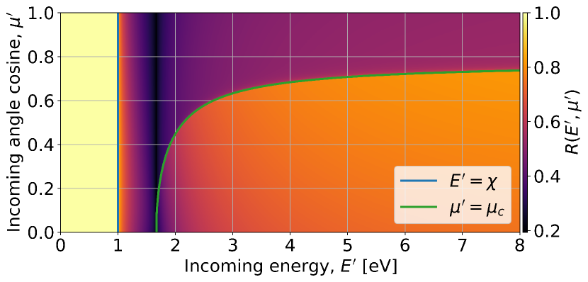
From Eq. 5 and 6 we note two particularly important features. First, Eq. 5 is only valid for , with particles of having insufficient energy to penetrate the material and thus a sticking probability of zero; that is, any electron with energy under the material electron affinity will be reflected. Second, we can identify a critical angle from Eq. 6, below which the electron inside the wall is in a evanescent wave and therefore also will be perfectly reflected. For , , the transmission probability is high.
To account for imperfections in the material, which cause a failure to perfectly conserve lateral momentum, this equation is modified to represent a disordered interface with a fitting factor representing the wall roughness:
| (7) |
Values of and match experimental data extremely well for magnesium oxide, though values throughout the range approaching the strong scattering limit also give superior fits to and decently represent the data.Bronold and Fehske (2015) For this work, the value of is used, and it is assumed in the dearth of widely available low-energy experimental data that this choice of parameter remains sufficiently applicable for other dielectric materials. As Eq. 7 gives the sticking probability, the electron reflection probability is
| (8) |
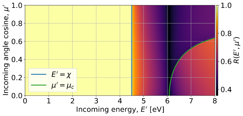
which is plotted for a low electron affinity case and high electron affinity case in Fig. 2. The materials chosen to represent these cases are magnesium oxide (, )Bronold and Fehske (2015) and boron nitride (,Rumyantsev et al. (2001) Xu and Ching (1991)), respectively. Note that while the addition of surface imperfections reduces the probability of reflection from unity for , for perfect reflection continues to occur. The presence of this region of guaranteed backscattering, particularly in cases such as those featured in this work where the bulk of the distribution is at low energy, causes the material emission to be largely dictated by the magnitude of the material electron affinity.
Eq. 8 can be fully discretized and precomputed across the boundary of the simulation velocity space.Cagas, Hakim, and Srinivasan (2020a) The resulting reflection boundary condition defines the outgoing electron distribution at the wall boundary as the incoming distribution scaled by the reflection function integrated over incoming velocity space
| (9) |
II.2 Problem setup
The full VM-FP system of equations is 6D in space and velocity (3X3V). However, for the purposes of the simulations here, 1X2V dimensions are deemed sufficient to capture the behavior in the directions normal () and tangential () to the material boundary. Two velocity space dimensions are necessary as a single velocity dimension effectively fixes , which only permits electron motion normal to the wall. Thus, only the energy dependence is truly accounted for by the boundary condition in 1X1V. In order to properly examine the angular dependence of the electron emission, an additional velocity dimension is required. 1X1V simulations are used in this section as a means of benchmarking the problem setup.
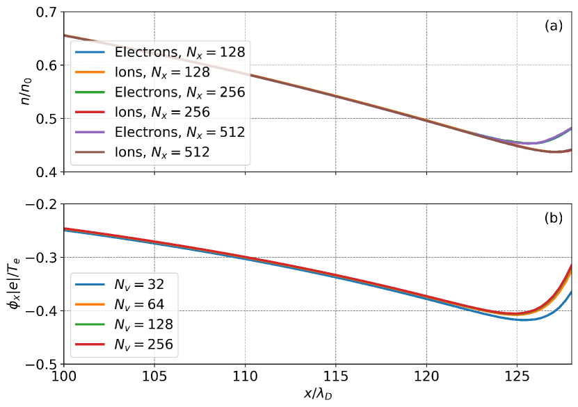
The results presented here are run on a uniform grid with a resolution of , . This provides in the minimum cell resolution needed to resolve , while in , this resolution is sufficient to accurately capture the distribution function dynamics which determine the sheath structure (Fig. 4). The plasma is initialized using singly-ionized ions with a mass ratio . Both the electron and ion species are initialized to a Maxwellian distribution
| (10) |
where is the number of velocity dimensions, is the density profile for species , and is the drift speed profile. These profiles are found by solving the system of ordinary differential equations (ODEs) which give the Robertson approximation of the steady-state sheath solutionRobertson (2013) for the potential , electric field , and ion drift speed :
| (11) |
| (12) |
| (13) |
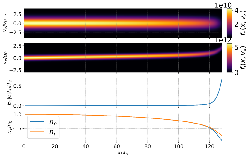
Here is an ionization source term where is the domain length. The densities are then calculated from and . The Maxwellians are initialized with an electron and ion temperature in the presheath of and , and density . Here, electron thermal velocity is used to normalize the electron results and the Bohm speed is used for the ion results. There is no magnetic field initialized, and it remains negligible throughout the simulation. The resulting initial distributions, density profiles, and fields are shown in Fig. 3.
Since a domain with a wall on each side yields symmetric results, taking advantage of this symmetry allows the simulation domain to be reduced by half with a perfect reflection boundary condition placed in what would otherwise be the center of the domain. This is done at the left boundary, while the right boundary uses the described Bronold-Fehske reflection function. The reflection function is precomputed by integrating over each velocity space cell during the initialization period of the simulation.
The reflection function boundary condition was applied previously to a simple sheath simulation using the material parameters of magnesium oxide in a dissertationCagas (2018) and paper.Cagas, Hakim, and Srinivasan (2020b) This work examines the dependence of the sheath formation on the material properties by comparison between two cases, a low electron affinity material (magnesium oxide) and a high electron affinity material (boron nitride).
Since particles are being lost to the wall, the source term for the electrons and ions is necessary to keep the total particle balance approximately constant. This may be implemented by taking the particle flux of each species and adding it back across a chosen source region, however, as the particle fluxes are not exactly equal this leads to a slight violation of quasineutrality in the presheath. To avoid this, it is desirable to add back equal numbers of electrons and ions with both additions being determined from the ion flux . This causes the total number of ions to remain constant, while the electrons fluctuate but approach a steady balance over time.
A standard approach to particle sources is to inject the particles at the presheath edge. This, however, invariably leads to the formation of a source sheath where a potential drop develops across the entrance of the presheath.Procassini, Birdsall, and Morse (1990) To minimize this, the particles are added back in a Maxwellian distribution at initial temperature with the density being scaled to a linearly decreasing profile across the source region ()
| (14) |
This, as opposed to simply injecting them at the left edge, prevents the formation of a pronounced source sheath.
II.3 Collisions
The electron distribution close to the wall in a classical plasma sheath is non-Maxwellian, particles with a high positive velocity are absorbed while the rest are deflected by the barrier electric field. This produces a distribution with a depleted negative velocity tail, a cutoff Maxwellian which propagates to the left and encounters the pure reflection boundary condition. The result is a feedback loop where the cutoff carries over into the distribution heading back towards the wall, leading to depletion of both high energy tails of the distribution all across the domain. In order to keep the presheath in a Maxwellian distribution and avoid this feedback loop, a Lenard-BernsteinDougherty (1964) (LBO, known also as a Dougherty operator) Coulomb collision operator is used to smooth the distribution.Hakim et al. (2020)
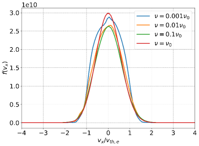
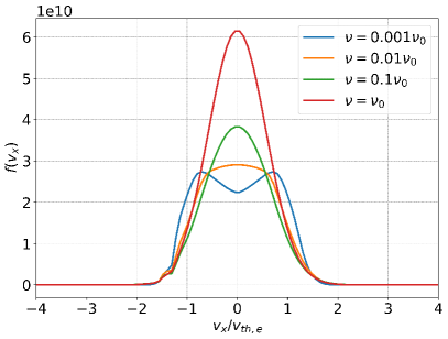
The true physical collision frequency, due to the small size of the domain being simulated, is insufficient to fully thermalize the Maxwellian in the presheath. In a realistic scenario, the plasma will extend far enough that the mean free path of the electrons is small enough compared to the plasma length to be collisional, while being much larger than the sheath size making collisions negligible in the sheath itself. In order to model the effects of a larger plasma length on the presheath, the collision frequency must be artificially inflated. The base self-species collision frequency is taken to be , which corresponds to a few collisions every transit time for a thermal particle. If the collisions are uniformly applied to the domain, a sufficiently high frequency to produce a smooth Maxwellian at the sheath entrance can greatly alter the resulting wall distribution (Fig. 5). As the Bronold and Fehske reflection function is reliant on not just the overall electron flux, but the particular shape of the distribution at the wall, this variation in distribution also significantly changes the overall gain behavior.
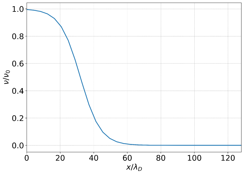
In a physical situation, Coulomb collision frequency varies as .Braginskii (1965) Both of these quantities drop in the sheath, though the greater weight of the temperature tends to cause collision frequency to counterintuitively rise in the sheath. However, as long as the sheath length is negligible compared to the mean free path, the sheath remains collisionless. Here, where the collision frequency is artificially inflated, this condition is not kept. Thus, while it is necessary to inflate the presheath collisionality, it is desirable to institute a spatially-varying collision profile that decreases as it approaches the sheath in order to fulfill the collisionless sheath condition. This is done by specifying a collision frequency profile that follows a sigmoid function
| (15) |
and is constant in time (Fig. 6). The cross-species collision frequencies are related to the self-species as , .Braginskii (1965) Inter- and intra-species collisions are included for electrons and ions.
III Sheaths with material boundaries
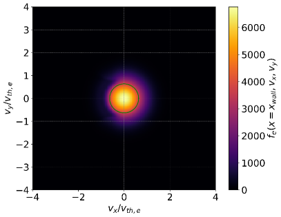
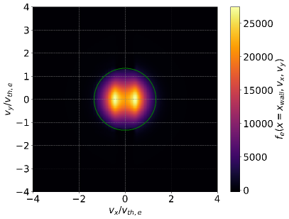
The resulting sheath profiles are shown in Fig. 7. The boron nitride develops an SCL sheath, while the magnesium oxide remains monotonic. Fig. 8 compares the electron distribution functions of the different materials at the wall, with the electron affinity threshold marked in green. With the high affinity case, the great majority of the distribution function lies inside the threshold and is reflected. Higher gain results in a reduction in the magnitude of the sheath potential, which in turn changes the shape of the distribution function. For the high affinity material, the increase in potential between the minimum sheath potential and the wall potential accelerates the electrons of the distribution function, depleting the center and causing a high velocity peak to form in the tail of the distribution. This does not occur in the low affinity case as the minimum sheath potential is at the wall, and the incoming distribution is a smooth Maxwellian across and positive velocity space. The low affinity monotonic case is similar to the classical case, with the difference that the reduced sheath potential of the low affinity case allows marginally greater density to reach the wall than the classical case, and the distribution has a very visible cutoff (Fig. 8) corresponding to the features of the reflection function in Fig 2. The region is not as clear as the region due to the low distribution there, but is still apparent as the bumps in the tail of the emitted distribution in . Due to the very high proportion of particles that lie inside the region in the high electron affinity case, the cutoff and secondary region are much less apparent.
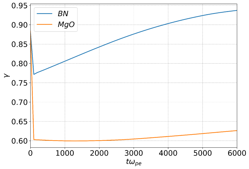
The gain, shown in Fig. 9, increases significantly in time for the high affinity case, while the lower affinity case remains approximately static for a time then begins to rise. The lack of a steady state is primarily due to collision-driven cooling. As energy is lost due to particle loss at the wall, the collisions relax the distribution to a Maxwellian at a lower temperature, preventing a true temperature equilibrium. Because the reflection is based on energy, this means a greater proportion of the distribution is consolidated inside the perfect reflection region, and thus gain increases with time. Because particle loss to the wall is small, the source at initial temperature does not add back sufficient distribution to counteract this cooling. This cooling also occurs in the low affinity case, but the gain does not necessarily increase as a greater portion of the distribution is present in high-reflection regions farther away from the affinity threshold, which during cooling will migrate to the low-reflection region directly outside the cutoff. This results in the more mellow gain behavior for the low affinity case, though later in time it too sees the distribution begin to consolidate within the pure reflection region. In the high affinity case, this is exacerbated by low energy reflected particles being trapped by the potential barrier, leading to density accumulation at the wall. This is counterbalanced somewhat by the double peak which forms from particles being accelerated towards the wall by the barrier, shown in Fig. 8. Since the reflection is elastic, these particles maintain their higher energy upon being emitted, which allows more of them to escape. Fig. 5 demonstrates this for the 1X1V case, as the density is significantly higher at the wall in the high collisions case where the double peak cannot form. Still, the combination of these processes is expected to continue to drive the gain trend towards unity. It should be noted that while one might expect the collision-based cooling to be mitigated in a simulation that accounts for the physical situation where plasma is constantly flowing into the domain at a hot temperature, the trapping of low energy particles which are unable to penetrate the material by the potential well is a physically reasonable result. For the purposes of demonstrating the range of sheath behaviors possible for different material parameters under the present model, addressing the lack of a steady state is not considered critical. Future work focused on more rigorous treatment of specific applications will treat the question of whether a physical steady state is achieved more closely.
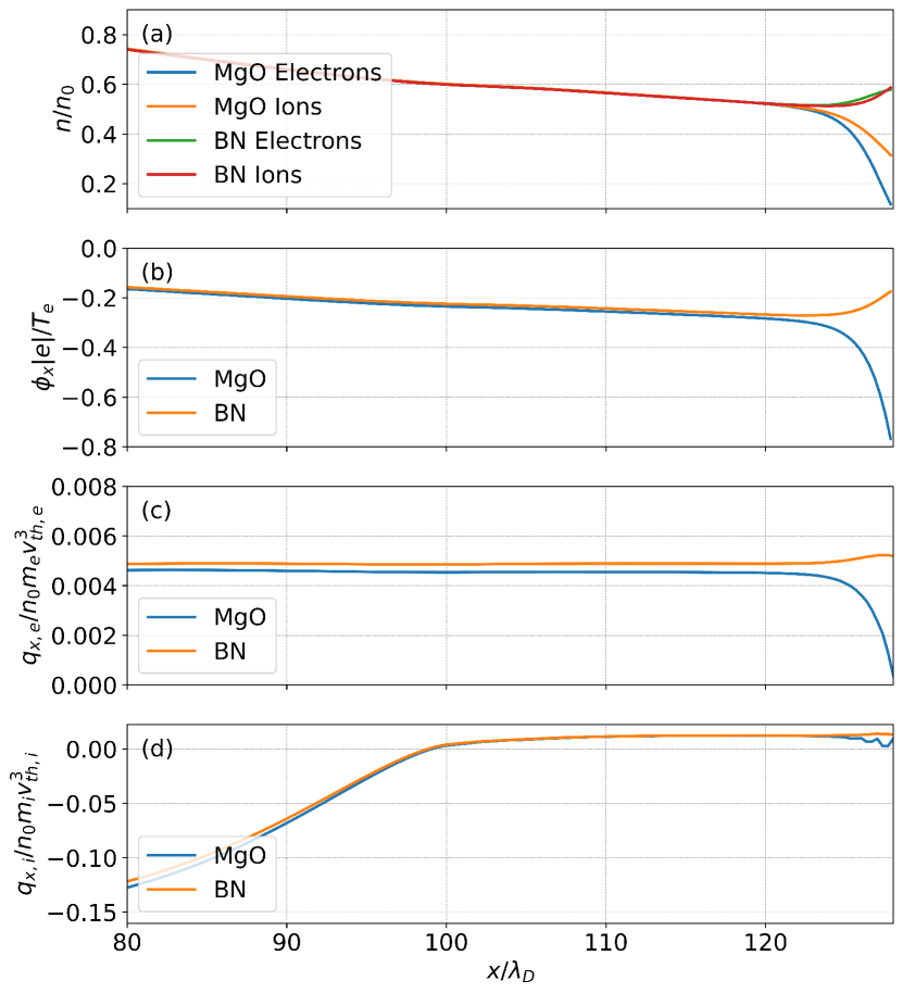
The heat flux of a plasma is defined in the fluid frame of the species asWang et al. (2015)
| (16) |
representing the net energy transfer due to the spread of the distribution from the drift speed . Fig. 7(c)(d) presents the heat flux for the two materials. The heat flux is calculated from the total energy flux densityWang et al. (2015)
| (17) |
where is the third moment of the distribution function, and are the total fluid pressure and energy, respectively, and is the viscous stress tensor. This can be rewritten and solved for directly in terms of the moments of the distribution function in 1X2V for the direction:
| (18) |
where is the second moment of the distribution function, and is the zeroth moment of the distribution function. Fig. 7(c) shows significant variation in the electron heat flux between the different cases. In the high affinity case, the SCL region causes the heat flux to increase into the sheath with a slight drop at the wall. Contrarily, heat flux dips significantly towards zero near the wall for the low affinity case.
The results shown here are subject to several limitations, many of which will be the focus of future work. While the importance of accounting for the high reflection rates that can occur in the low-energy region of the distribution has been demonstrated, high energy effects such as the rediffusion of particles and emission of true secondary electrons may come into play in the tail of the distribution. Particularly if the acceleration of particles observed in the SCL case due to high electron reflection occurs, it could lead to a feedback loop between emission mechanisms. Higher energy particles would cause emission of cold true secondary electrons, which would further drive the backscattering explored here. Additionally, accounting for such processes could likely drive the emission into the regime, potentially introducing a reverse sheath transition which would further accelerate electrons into the wall. Working towards a holistic understanding of these emission mechanisms across the entire range of the relevant electron energy distribution and how they interact is the primary focus of ongoing research. In plasma-material interactions, secondary electron emission is driven by ion impact as well as electron impact, something not addressed in this work which is also the subject of ongoing development.
The present work is also done in the absence of the applied magnetic fields and currents found in many thruster and fusion devices. The primary limitation towards magnetized sheath simulations is the computational expense of extending the boundary condition to a full 1X3V configuration, which would be required to capture the resultant gyromotion. This may be revisited in future work. Parallel work is being done on fusion-relevant cases with continuum kinetic sheaths in the presence of bias potentials,Skolar et al. (2022) with an eye towards the future consideration of electron and ion impact secondary electron emission models.
IV Conclusion
A continuum kinetic framework for simulating low-energy electron backscattering from a dielectric surface was demonstrated, with results presented for high and low emission materials. Source terms and an implementation of Coulomb collisions were considered, with it being demonstrated that the collision implementation in particular can significantly alter the distribution in the sheath region. Different materials can significantly impact the electron flux gain in the system, which can drastically change the fundamental sheath potential and density structures, while also greatly affecting the distribution of electrons and energy fluxes experienced at the boundary. Materials with a high electron affinity have a large perfect reflection region, which can result in the formation of a space-charge limited sheath, with a potential barrier forming sufficient to accelerate the electron distribution towards a higher energy peak. Due to backscattering being elastic, this results in a corresponding population of higher energy particles being emitted.
While demonstrated here for a simple unmagnetized sheath case, this work provides a foundation for future extension towards magnetized and bias potential sheath applications more relevant to plasma thrusters and fusion devices. Present work focuses on expanding the treatment of the wall emission to account for the intersection of high and low energy emission models, with additional efforts towards developing an implementation of ion impact driven secondary electron emission.
Acknowledgements.
The work presented here was supported by the U.S. Department of Energy ARPA-E BETHE program under Grant No. DE-AR0001263. The authors acknowledge Advanced Research Computing at Virginia Tech for supplying computational resources and support for this work.Data Availability Statement
All the work presented in this paper was produced by and is reproducible using the open-source Gkeyll software. Information for obtaining and running Gkeyll may be found on the documentation site.Gkeyll (2022) The input files for the simulations used to produce the results in this paper may be acquired from the repository at https://github.com/ammarhakim/gkyl-paper-inp/tree/master/2022_PoP_SheathSEE.
References
- Langmuir (1923) I. Langmuir, “The effect of space charge and initial velocities on the potential distribution and thermionic current between parallel plane electrodes,” Phys. Rev. 21, 419–435 (1923).
- Riemann (1991) K.-U. Riemann, “The bohm criterion and sheath formation,” Journal of Physics D: Applied Physics 24, 493 (1991).
- Robertson (2013) S. Robertson, “Sheaths in laboratory and space plasmas,” Plasma Phys. Control. Fusion 55, 93001 (2013).
- Bohm (1949) D. Bohm, The Characteristics of Electrical Discharges in Magnetic Fields (MacGraw-Hill, New York, 1949).
- Tang and Guo (2016) X.-Z. Tang and Z. Guo, “Critical role of electron heat flux on bohm criterion,” (2016), https://doi.org/10.1063/1.4971808 .
- Li et al. (2022) Y. Li, B. Srinivasan, Y. Zhang, and X.-Z. Tang, “Bohm criterion of plasma sheaths away from asymptotic limit,” (2022), arXiv:2201.11191 [physics.plasm-ph] .
- Cagas et al. (2017) P. Cagas, A. Hakim, J. Juno, and B. Srinivasan, “Continuum kinetic and multi-fluid simulations of classical sheaths,” Physics of Plasmas 24, 022118 (2017), https://doi.org/10.1063/1.4976544 .
- Hobbs and Wesson (1967) G. Hobbs and J. Wesson, “Heat flow through a langmuir sheath in the presence of electron emission,” Plasma Physics 9, 85 (1967).
- Sheehan et al. (2014) J. P. Sheehan, I. D. Kaganovich, H. Wang, D. Sydorenko, Y. Raitses, and N. Hershkowitz, “Effects of emitted electron temperature on the plasma sheath,” Physics of Plasmas 21, 063502 (2014), https://doi.org/10.1063/1.4882260 .
- Schwager (1993) L. A. Schwager, “Effects of secondary and thermionic electron emission on the collector and source sheaths of a finite ion temperature plasma using kinetic theory and numerical simulation,” Physics of Fluids 5, 631 (1993).
- Campanell (2013) M. D. Campanell, “Negative plasma potential relative to electron-emitting surfaces,” Phys. Rev. E 88, 033103 (2013).
- Campanell and Umansky (2016) M. D. Campanell and M. V. Umansky, “Strongly emitting surfaces unable to float below plasma potential,” Phys. Rev. Lett. 116, 085003 (2016).
- Jensen (2018) K. Jensen, Introduction to the Physics of Electron Emission (John Wiley & Sons, Inc, New Jersey, 2018) pp. 155–161.
- Chung and Everhart (1974) M. S. Chung and T. E. Everhart, “Simple calculation of energy distribution of low-energy secondary electrons emitted from metals under electron bombardment,” 45, 707 (1974).
- Scholtz, Dijkkamp, and Schmitz (1996) J. Scholtz, D. Dijkkamp, and R. Schmitz, “Secondary electron emission properties,” Philips Journal of Research 50, 375–389 (1996), new Flat, Thin Display Technology.
- Furman and Pivi (2002) M. A. Furman and M. T. F. Pivi, “Probabilistic model for the simulation of secondary electron emission,” Phys. Rev. ST Accel. Beams 5, 124404 (2002).
- Dunaevsky, Raitses, and Fisch (2003) A. Dunaevsky, Y. Raitses, and N. Fisch, “Secondary electron emission from dielectric materials of a hall thruster with segmented electrodes,” Physics of Plasmas 10, 2574–2577 (2003).
- Stangeby and McCracken (1990) P. Stangeby and G. McCracken, “Plasma boundary phenomena in tokamaks,” Nuclear Fusion 30, 1225 (1990).
- Bronold and Fehske (2015) F. X. Bronold and H. Fehske, “Absorption of an electron by a dielectric wall,” Physical Review Letters 115 (2015), 10.1103/physrevlett.115.225001.
- Dougherty (1964) J. P. Dougherty, “Model Fokker-Planck Equation for a Plasma and Its Solution,” Physics of Fluids 7, 1788–1799 (1964).
- Cockburn and Shu (2001) B. Cockburn and C.-W. Shu, “Runge–kutta discontinuous galerkin methods for convection-dominated problems,” Journal of Scientific Computing 16, 173–261 (2001).
- Hakim, Hammett, and Shi (2014) A. H. Hakim, G. W. Hammett, and E. L. Shi, “On discontinuous galerkin discretizations of second-order derivatives,” (2014), arXiv:1405.5907 [physics.comp-ph] .
- Juno et al. (2018) J. Juno, A. Hakim, J. TenBarge, E. Shi, and W. Dorland, “Discontinuous galerkin algorithms for fully kinetic plasmas,” Journal of Computational Physics 353, 110–147 (2018).
- Juno (2020) J. Juno, “A deep dive into the distribution function: Understanding phase space dynamics with continuum vlasov-maxwell simulations,” (2020), arXiv:2005.13539 [physics.plasm-ph] .
- Hakim and Juno (2020) A. Hakim and J. Juno, “Alias-free, matrix-free, and quadrature-free discontinuous galerkin algorithms for (plasma) kinetic equations,” in Proceedings of the International Conference for High Performance Computing, Networking, Storage and Analysis (IEEE Press, 2020).
- Hakim et al. (2020) A. Hakim, M. Francisquez, J. Juno, and G. W. Hammett, “Conservative discontinuous galerkin schemes for nonlinear dougherty–fokker–planck collision operators,” Journal of Plasma Physics 86, 905860403 (2020).
- Rumyantsev et al. (2001) S. Rumyantsev, M. Levinshtein, A. Jackson, S. Mohammmad, G. Harris, M. Spencer, and M. Shur, Properties of Advanced Semiconductor Materials GaN, AlN, InN, BN, SiC, SiGe (John Wiley & Sons, Inc., New York, 2001) pp. 67–92.
- Xu and Ching (1991) Y.-N. Xu and W. Y. Ching, “Calculation of ground-state and optical properties of boron nitrides in the hexagonal, cubic, and wurtzite structures,” Phys. Rev. B 44, 7787–7798 (1991).
- Cagas, Hakim, and Srinivasan (2020a) P. Cagas, A. Hakim, and B. Srinivasan, “Plasma-material boundary conditions for discontinuous galerkin continuum-kinetic simulations, with a focus on secondary electron emission,” Journal of Computational Physics 406, 109215 (2020a).
- Cagas (2018) P. Cagas, “Continuum kinetic simulations of plasma sheaths and instabilities,” (2018), arXiv:1809.06368 [physics.plasm-ph] .
- Cagas, Hakim, and Srinivasan (2020b) P. Cagas, A. Hakim, and B. Srinivasan, “Plasma-material boundary conditions for discontinuous galerkin continuum-kinetic simulations, with a focus on secondary electron emission,” Journal of Computational Physics 406, 109215 (2020b).
- Procassini, Birdsall, and Morse (1990) R. J. Procassini, C. K. Birdsall, and E. C. Morse, “A fully kinetic, selfconsistent particle simulation model of the collisionless plasma-sheath region,” Physics of Fluids B 2 (1990), 10.1063/1.859229.
- Braginskii (1965) S. I. Braginskii, “Transport processes in a plasma,” (1965).
- Wang et al. (2015) L. Wang, A. H. Hakim, A. Bhattacharjee, and K. Germaschewski, “Comparison of multi-fluid moment models with particle-in-cell simulations of collisionless magnetic reconnection,” Physics of Plasmas 22, 012108 (2015).
- Skolar et al. (2022) C. R. Skolar, K. Bradshaw, J. Juno, and B. Srinivasan, “Continuum kinetic investigation of the impact of bias potentials in the current saturation regime on sheath formation,” (2022).
- Gkeyll (2022) Gkeyll, (2022), https://gkeyll.readthedocs.io.