Fourier Synthesis Dispersion Engineering of Photonic Crystal Microrings for Broadband Frequency Combs
Abstract
Dispersion engineering of microring resonators is crucial for optical frequency comb applications, to achieve targeted bandwidths and powers of individual comb teeth. However, conventional microrings only present two geometric degrees of freedom – width and thickness – which limits the degree to which dispersion can be controlled. We present a technique where we tune individual resonance frequencies for arbitrary dispersion tailoring. Using a photonic crystal microring resonator that induces coupling to both directions of propagation within the ring, we investigate an intuitive design based on Fourier synthesis. Here, the desired photonic crystal spatial profile is obtained through a Fourier relationship with the targeted modal frequency shifts, where each modal shift is determined based on the corresponding effective index modulation of the ring. Experimentally, we demonstrate several distinct dispersion profiles over dozens of modes in transverse magnetic polarization. In contrast, we find that the transverse electric polarization requires a more advanced model that accounts for the discontinuity of the field at the modulated interface. Finally, we present simulations showing arbitrary frequency comb spectral envelope tailoring using our Frequency synthesis approach.
Introduction
Frequency combs based on integrated nonlinear microresonators are a powerful tool to bring metrology outside the lab. They allow for low power consumption and portabilty SternNature2018 while maintaining metrological quality SpencerNature2018 while in the dissipative Kerr soliton (DKS) regime. Although octave-spanning frequency combs – needed for carrier-envelope stabilization through self-referencing of the comb – have been demonstrated LiOptica2017 ; PfeifferOpticaOPTICA2017 , reaching beyond an octave is particularly interesting so that the strong pump can be doubled in self-referencing schemes. Yet, it is extremely challenging, especially at short wavelengths towards the visible. Materials that are used for microcomb generation, including \ceSi3N4 BraschScience2016 ; NazemosadatPhys.Rev.A2021 ; YeLaserPhotonicsRev.2022 ; MoilleNat.Commun.2021 ; ShenNature2020 , \ceAlN BruchNat.Photonics2021 , and \ceLiNbO3 WangNatCommun2019 , present increasingly large normal dispersion the shorter the wavelength is LeeNatCommun2017 ; MoilleOpt.Lett.OL2021 ; MoilleCLEO20222022 . Modal confinement of the light in resonators with wavelength-scale cross-sections adds a geometrical component to the dispersion, which in many cases is enough to compensate for the normal material dispersion. However, a simple rectangular cross-section microresonator does not offer enough degrees of freedom to achieve broad enough anomalous dispersion (needed for bright DKS states) to tackle goals such as spectral bandwidths well-beyond an octave while extending well into the visible. Alternative approaches have been proposed. Among them, multi-pumped DKS MoilleNat.Commun.2021 and pulsed-pump resonators AndersonNatCommun2022 ; AndersonOptica2021 have been successful in realizing spectral bandwidths beyond that of conventional DKS microcombs. Yet, these solutions often increase the complexity of the setup required for field deployment of these microcombs. It is thus necessary to create methods through which one can engineer the dispersion of a microring resonator. Approaches with multi-layer material stacks DorcheOpt.ExpressOE2020 , complex ring cross-sections MoilleOpt.Lett.OL2018 and concentrical rings KimNat.Commun.2017 – each relying on avoided-mode crossings – have generated much more complex dispersion profiles. However, fabrication has been challenging and may be incompatible with top-down foundry-like mass fabrication processes LiuNatCommun2021a . In addition, broad bandwidth microcombs based on these approaches have not yet been demonstrated. Nevertheless, the concept of an avoided-mode crossing, which relies on mode-coupling, can be harnessed in different fashions, for example, by coupling the clockwise (CW) and counterclockwise (CCW) directions of the same transverse optical mode. Such CW/CCW coupling has been demonstrated by Lu et al., where modulation of the microresonator sidewall creates a photonic crystal that frequency splits a targeted mode without impacting the nearest neighbors, determined by the number of photonic crystal periods within the ring circumference LuAppl.Phys.Lett.2014 . Interestingly, nonlinear states such as optical parametric oscillation BlackOpticaOPTICA2022 ; LuOpt.Lett.OL2022 ; StonearXiv2022 and DKSs can be created in this system YuNat.Photonics2021 . Moreover, this photonic crystal ring concept has been expanded to modulation amplitudes far beyond a simple perturbation, where a full band gap of hundreds of gigahertz to several terahertz is resolved, impacting the band structure among several neighboring modes LuNat.Photon.2022 . More importantly for this work, it has been shown that it is possible to introduce multi-period photonic crystal patternings that create controlled frequency splittings for a few (up to 5) targeted modes LuPhotonicsRes.2020 . In particular, sinusoidal ring width modulations corresponding to multiple single modes targeted simultaneously (i.e. with different amplitudes and modulation periods) can be summed with limited impact to the other modes. In summary, ref. LuPhotonicsRes.2020 lays out a methodology based on Fourier synthesis for microring dispersion engineering MoilleConf.LasersElectro-Opt.2022Pap.STh2F32022 , where a spectral profile of mode coupling and corresponding shift of several individual modal frequencies follows a discrete Fourier transform of the ring width modulation.
Yet, whether a vast number of mode-couplings through Fourier synthesis – which remains a perturbative appraoch – can be implemented in a predictive manner that yields precise and efficient dispersion engineering consistent with the needs of, for example, broadband microresonator frequency combs is still unclear. In this work, we propose to answer this question with an in-depth study of photonic-crystal-mediated microring dispersion engineering in the limit of large (tens of gigahertz) spectral shifts. We demonstrate that the previously utilized simple analysis that links the modal frequency shifts directly to ring width modulation is inaccurate in our regime of interest. In contrast, modulation of the ring effective refractive index, which is mapped (nonlinearly) to a ring width modulation, is a better approach. We also show that the polarization considered greatly impacts the validity of the perturbative approach with which this mode-by-mode dispersion engineering is predicted using our Fourier synthesis model. This limit arises from the boundary conditions on the dominant electric field components at discontinuous boundaries. Consequently, the transverse magnetic polarization is more suited for predictive dispersion engineering using our straightforward Fourier synthesis approach, while the transverse electric polarization may require an approach based on full three-dimensional numerical simulations of Maxwell’s equations in modulated microring structures. Using our technique, we fabricate silicon nitride photonic crystal microrings in which dozens of resonances are shifted in a controlled fashion by up to 50 \unitGHz, compatible with the integrated dispersion mitigation needed for broadband (e.g., octave-spanning) combs, and in good agreement with simulations. Finally, we use coupled Lugiato-Lefever equation modeling to predict the spectral behavior of microcombs that can be generated using our dispersion technique, and in particular, the possibility of considerably extending their bandwidth and the possibility of creating multi-color Bragg solitons.
Results
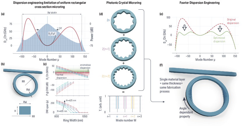
Towards a broad and flat microcomb spectrum: motivating photonic crystal dispersion engineering. Under the right conditions of pump power and detuning, microcombs based on the third-order optical nonlinearity can support DKS states KippenbergScience2018 . The usual way of studying the dynamics of such a system is through the Lugiato-Lefever equation LugiatoPhys.Rev.Lett.1987 which is essentially a dissipative nonlinear Schrödinger equation HanssonPhys.Rev.A2013 that takes into account the microring resonator’s periodic boundary conditions while operating under a slow varying envelope (mean-field) approximation ChemboPhys.Rev.A2013 . The single DKS solution in the anomalous dispersion regime follows the well-known hyperbolic secant (sech) spectral envelope (sech2 for spectral intensity). To quantify the resonator dispersion, the community usually opts for a Taylor expansion and defines a quantity termed the integrated dispersion , with being the linear repetition rate at the pumped mode with resonant frequency , and the azimuthal mode number referenced to the pumped mode. The higher order dispersion terms are of great importance as they drive the shape of the integrated dispersion and, ultimately, the properties of the microcomb. The sech2 comb envelope width is inversely proportional to , which must be positive for anomalous dispersion. The odd terms drive the recoil of the soliton, resulting in the drift of its repetition rate away from the linear one. The even terms are responsible for symmetric zero crossings of and yield dual dispersive waves (DWs) as comb teeth become resonant at these modal frequencies. The experimental demonstrations of DWs BraschScience2016 have fundamentally changed the landscape of microcombs by bypassing the sech2 width driven by and expanding it to octave span LiOptica2017 ; PfeifferOpticaOPTICA2017 . In this work, we will refer to the frequency span between the frequencies as the ‘dispersive wave span’ of the microcomb [Fig. 1(a)-(b)]. Although these DWs have been the key enabler for broadband microcombs, the power in these modes relies on the available power in the sech2 soliton envelope. Therefore, if is too large, leading to a sharp comb envelope close to the pump, the power available at the DW locations will be insignificant for resonant enhancement. This encapsulates the dispersion engineering challenge for broadband integrated frequency combs: getting as broad as possible the zero-crossings while keeping the portion as flat as possible.
Guided-wave photonics results in wavelength-dependent light confinement: the longer the wavelength, the larger the mode and less confined it is. This unique feature allows one to tailor the dispersion beyond the material dispersion. For a microring resonator, there are essentially three user-defined input parameters: ring radius (), ring width (), and thickness () [Fig. 1(b)]. The mainly acts on and typically has little influence on the higher order dispersion terms. Therefore, most dispersion engineering efforts focus on and . However, with only these two parameters available, the DW span and increase together [Fig. 1(c)]. Although increasing the comb width is the ultimate goal, increasing reduces the power available at the zero-crossings, ultimately preventing useful DWs from forming. Thus, with current dispersion engineering approaches, an apparent trade-off exists.
In recent years, a modified microring resonator has been developed, where modulation of the ring width allows for coherent backscattering between the clockwise (CW) and counter-clockwise (CCW) traveling wave modes LuAppl.Phys.Lett.2014 ; LuPhotonicsRes.2020 . It has been demonstrated, using a perturbative approach theoretically and verified experimentally, that a single harmonic modulation of the ring width results in a single azimuthal mode of a given transverse spatial mode family experiencing this coupling LuAppl.Phys.Lett.2014 . These two coupled modes hybridize into symmetric and anti-symmetric modes, creating a mode splitting proportional to the amplitude of the modulation [Fig. 1(d)]. In the unmodulated ring, the necessity to match the field phase after one round trip results in a set of azimuthal modes described by a mode number . When the modulation is applied, a new spatial period becomes important. Here, the modulation consists of periods around the ring circumference. In the language of photonic crystals (PhCs) joannopoulosPhotonicCrystalsMolding2008 , the frequency splitting created by coupling of the CW and CCW azimuthal modes at is a frequency band gap, with the Brillouin zone folded at these points as well. These modulated devices can thus be referred to as photonic crystal (PhC) microrings, and in the limit of strong modulation, large band gaps of several terahertz have been demonstrated while maintaining high optical quality factor () LuNat.Photon.2022 . In addition, smaller modulation PhC microrings have been used to change the dynamics of DKS formation YuNat.Photonics2021 . For smaller modulations, it has also been shown that the splitting is linearly proportional to the modulation amplitude employed, and that the CW/CCW coupling is nearly absent for all modes near the targeted mode LuPhotonicsRes.2020 . Therefore multiple mode splittings (PhC modulations) can be implemented on a single ring. Following ref. LuPhotonicsRes.2020 , the design rules then become simple: a straightforward sum of individual modulation patterns gives the microring ring width modulation to implement [Fig. 1(d)], such that with the modulation intensity of each targeted mode and the microring azimuthal angle. Therefore, the total ring width modulation in this scheme is, per definition, the discrete inverse Fourier transformation (DFT) of the modal coupling envelope .
The frequency shift created by the CW/CCW coupling can be used to modify the dispersion of the resonator locally. The integrated dispersion is then shifted by half the resonance splitting at each coupled mode, creating two bands. One band is pushed toward higher , and one reduces the value of . The latter can overcome the aforementioned trade-off in large and large potential comb bandwidth if the Fourier synthesis design approach allows for predictive mode shifts in the tens of gigahertz range to counterbalance the maximum value of an octave-spanning comb. By carefully engineering the coupling, one could create flatter integrated dispersion while obtaining a large comb width [Fig. 1(e)]. The resulting microring resonator undergoes a local ring width modulation consistent with the inverse DFT [Fig. 1(f)]. Such a system is compatible with standard single device layer fabrication as only the ring width as a function of angle is modified, and no other fabrication steps or materials are added.
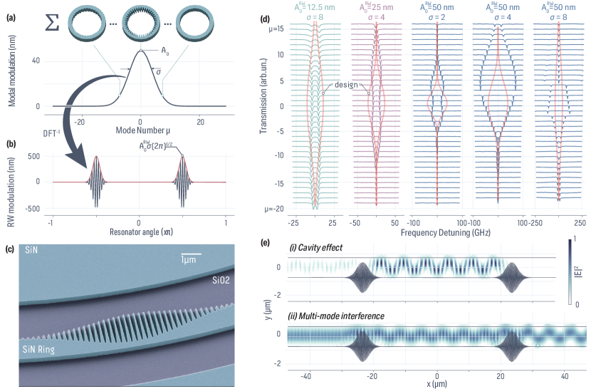
Limitations of a direct implementation of the ring width modulation In this section, we seek to verify the above approach for predictive dispersion engineering. We fabricate devices with \unitnm thick silicon nitride (\ceSi3N4), nominal ring width \unitnm, and radius \unitum on top of silicon dioxide (\ceSiO2) without any top cladding other than air. We implement a targeted Gaussian modal envelope (in mode number space) defined by , where is the mode number relative to a centered one set at [Fig. 2(a)], and is chosen based on the desired maximum frequency splitting. At the moment, only the fundamental transverse electric mode (TE0) will be considered, which we have determined through finite element method (FEM) simulation to be at 193.6 \unitTHz at . In the layout, we vary the maximum amplitude of the Gaussian and its width while other parameters are fixed. The resulting summed modulation profile follows, as expected, the inverse DFT profile (Fig. 2(b)). The envelope of the modulation is therefore also a Gaussian, and the mapping between frequency splitting of a given mode and real-space RW modulation amplitude is linear, based on the simple perturbative analysis from ref. LuPhotonicsRes.2020 . After summing these different modulations, the maximum real-space modulation of the ring width is , and is much larger than , which is the maximum of the modal Gaussian profile [Fig. 2(a)-(b)], and the consequences of which will be discussed shortly. The maximum modulation could be reduced if a phase shift is applied to each modal modulation. Yet, the symmetric and anti-symmetric modes arising from CW/CCW coupling are intrinsically standing waves, with their spatial mode profiles along the azimuthal direction locked by the node and anti-node positions of the modulation. Applying such a phase shift might not be desirable as it could reduce nonlinear interaction between between modes. Thus, we will only study the extreme modulation case where for Fourier synthesis dispersion engineering which if demonstrated to work should be applicable for arbitrary . A zoom-in scanning electron microscope image of a fabricated device, created using high-resolution electron-beam lithography, is shown in Fig. 2(c).
We proceed with transmission spectroscopy measurements between 185.18 THz and 198.6 THz (i.e. 1510 \unitnm and 1620 \unitnm) of the ring resonators with different modulation amplitude and width, where each resonance is spaced by a free spectral range of 398 \unitGHz. A stacked-up representation of the transmission around each resonance is represented in Fig. 2(d), highlighting the spectral profile of the modal coupling obtained (i.e., mode splitting vs. mode number). However, while overlapping this experimental data with the originally designed coupling from the direct inverse DFT, it is evident that none of the experimental data match. In particular, multiple behaviors are reported with the “collapsing” of the splitting around for small modulation amplitude and/or small width , while at large and large , the modal coupling becomes much more unpredictable. The maximum coupling for each design has been calibrated with a single mode coupling at . It is worth reporting that nm and yields nm, which is far from the upper range of what has been previously experimentally verified and confirmed to match predictions based on a perturbative approach LuPhotonicsRes.2020 .
We propose that the discrepancy between designs and experiments comes from two fundamental interactions in the PhC ring, which we highlight through finite-difference time-domain (FDTD) simulations. Here, we consider a simple FDTD simulation whose intent is to provide a qualitative assessment of these complicating factors. To highlight qualitative features while retaining a small enough structure to avoid convergence and/or simulation time issues, we consider a waveguide containing two highly modulated regions, as shown in Fig. 2(e). First, under a total modulation where the becomes small enough, a cavity-like effect will occur with boundaries localized at the local modulated sections of the ring [Fig. 2(e,i)]. Essentially the propagating modes – either CW or CCW – will also be coupled to this cavity mode, making the mode splitting much more complex. We believe such an effect is mostly seen in the higher modulation case, as highlighted in nm and . The second effect that comes into play is the multi-mode interference. The modulation, in particular reducing the ring width, allows for a non-zero overlap between the higher-order transverse spatial modes of the unperturbed ring. Similar to an unoptimized racetrack resonator JiCommunPhys2022 , this yields a coupling between these modes, which adds up to the CW/CCW one and creates a much more complex pattern of mode splitting. This multi-mode interference effect is also associated with higher radiation losses and quality factor asymmetry, as can be seen for in the case of nm and in Fig. 2(d)
Effective index approach: improved Fourier synthesis and polarization considerations
We have demonstrated that direct Fourier synthesis for predictable dispersion engineering using a simple modulation approach is inherently flawed when modulation amplitudes are sufficiently large. However, given that PhC band structures are intrinsically related to the modal , in this section we consider whether we can produce a better model for dispersion engineering with DFT design.
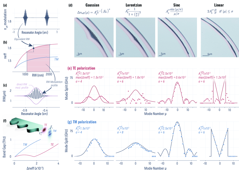
The modal effective refractive index is not linear with the , given that cut-off occurs in our asymmetrically air-clad system under a small enough and will grow asymptotically toward the silicon nitride index with large . Thus it is more suitable to apply the inverse DFT on the effective index modulation rather than the RW modulation [Fig. 3(a)]. The mapping between effective index and is easily achieved through finite element method simulations. Of course, this function will also depend on thickness and ring radius, yet we assume they are fixed throughout this study. From the inverse DFT profile along the resonator angle, it is then possible to map the actual modulation that we have to fabricate using this simulated calibration of [Fig. 3(b)]. It is instructive to notice the difference between the modulation profile obtained by the previous direct modulation method and the one described in this section [Fig. 3(c)]. In the former case, the maximum modulation is close to the nominal one, creating a local close to zero, which is responsible for the cavity-like and higher-order mode coupling presented earlier. It can be understood that the local variation of is much stronger than expected, creating a local cut-off that leads to strong Bragg reflection at that point. However, in the modulation case, the modulation accounts for the nonlinear dependence of with the ring width, in particular, the narrower it becomes. Therefore, the ring does not present the same bottle-neck effect, which reduces the two spurious effects partially responsible for the mode splitting not following the intended design. In addition, the “teeth” of the PhC are much sharper than in the simple sine modulation case, which we believe also reduces the PhC cavity mode within the Bragg grating. This also suggests that the upper modulation limit is not the unperturbed ring width, but is rather limited by either the disk (i.e. ) or the cut-off . This maximum modulation can be tailored with the nominal , but a trade-off must be found to allow for operating in the correct dispersion regime of the resonator for a given application (e.g., weak anomalous dispersion for a bright, broadband soliton microcomb).
Based on this new inverse DFT process, we proceed to fabricate four types of modal coupling designs (Fig. 3(d)) made around the same microring parameters presented in the previous section. We implement the same Gaussian profile, as well as a Lorentzian one defined by , a sinc pattern defined by , and a linear profile with and no coupling outside this range for this profile [Fig. 3(e)]. Measuring the TE0 modes, we retrieve the mode splitting for each resonance, where once again, experimental data and the modal coupling design do not match [Fig. 3(e)], except for the sinc profile.
To understand the origin of this discrepancy, it is important to recall some basic boundary conditions put forth in Maxwell’s equation, that is, that the electric field is discontinuous at the orthogonal interfaces of the polarization. While in this work we have used a simple perturbative expression for the coupling term between the CW and CCW modes (albeit while taking into account the waveguide effective modal index dependence on width), more generally, the coupling term between the CW and CCW modes can be semi-analytically determined by assuming a one-dimensional Bragg grating with two coupled counterpropagating waves. The transverse magnetic (TM) polarization – with the dominant electric field component along the thickness direction of the ring – does not experience a discontinuity at the modulated interface, which is also true for the magnetic field in this case along the radial direction [Fig. 3(f)]. Therefore, the coefficient between CW/CCW coupling can be expressed as with the magnetic mode profile along the radial direction of the ring. However, the TE mode experiences a discontinuity along the modulated ring wall. Thus, one needs to account for a correction term in the coupling such that LeeOpt.Lett.2019 . This translates into different behaviors of the band-gap (i.e. splitting amplitude) between the two polarizations, where the TM mode exhibits a continuously increasing band gap while the TE mode undergoes a band gap closing with the increase of the refractive index contrast of the PhC (Fig. 3(f), band gap obtained from FEM simulation). This difference in behavior can help explain the mismatch between design and experimental data in the TE polarization. Interestingly, the sinc profile effectively is a single targeted modulation that is truncated to match the sinc modal width. Therefore, much less effect due to the polarization will occur and the behavior is closer to the single mode splitting case, explaining the good agreement with the designed modal mode splitting profile. In addition, the maximum modulation for a given and is much smaller in the case of the sinc profile, which makes the system behave in the linear regime of band gap opening with modulation amplitude (e.g., as shown in Fig. 3(f)).
The above explanation suggests that the TM polarization should not suffer from such a theory-experiment disagreement for any profile. We measured the same microrings in the TM mode, where is resonant at 204.6 \unitTHz [Fig. 3(g)]. As expected from the absence of band gap closing due to the field continuity with the modulation, the TM mode follows the intended modal coupling design for all of the profiles implemented. We note that the maximum obtained mode-splitting reached up to 100 \unitGHz (i.e. coupling \unitGHz), which is compatible with integrated dispersion mitigation for ultra-broad microcomb generation. Nevertheless, it is fair to assume that larger coupling strength can be easily implemented. The quality factor for both TE and TM is not particularly impacted in the spectral region where the coupling happens and remains at the level (see supplementary Fig. 5). However, we believe that substantial losses will be introduced at shorter wavelengths. First, approaching the mode , the band folding will not occur between the two contra-propagative modes but instead with the direction in the reciprocal space of the PhC (i.e close to the surface normal direction). Therefore, the light will be extracted almost vertically. This is relevant for optical angular momentum generation LuArXiv2022 ; WangArXiv2022 , while for our frequency comb application, it will generate considerable loss given the strength of the PhC. Secondly, at short wavelengths, the modulation will not be subwavelength anymore, and will essentially act as a scattering element which is likely to cause losses.
Going forward, we note that with accurate modeling of the TE coupling between CW and CCW modes and the experimental demonstration of the band gap closing - which has already been observed in a large modulated PhC ring LuNat.Photon.2022 - along with accurate predictions of the effective modal refractive index, it may be possible to effectively develop Fourier synthesis dispersion engineering accurately in this polarization, though it may also be the case that full numerical solution of Maxwell’s equations within a modulating microring might be needed for accurate prediction of the dispersion. This work is outside of the scope of this manuscript; instead, in the next section, we focus on how understanding how the demonstrated Fourier synthesis dispersion engineering technique can impact microresonator frequency comb generation.
Broadband microcomb dispersion engineering and Bragg multi-color solitons using the Fourier synthesis approach. In this section, we numerically investigate the potential that the inverse DFT dispersion design could bring to ultra-broadband microcombs and the new kinds of microcombs that could be generated using this technique.
To accurately model the system, we use a set of linearly coupled Lugiato-Lefever equations (LLEs) that account for the CW and CCW interaction in the PhC ring. To account for the cross-phase modulation, we assume that the contra-propagative light will travel at twice the speed of light, given that the LLE is intrinsically in the moving frame of the light. Therefore, the cross-phase modulation can neglect the fast oscillations of the light and simply use the average of the contra-propagative mode power FanOpt.Lett.2020 :
| (1) |
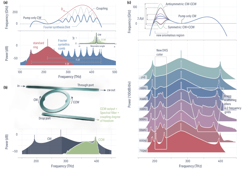
where and are the envelope field in the CW and CCW mode respectively, the temporal derivative, , the Fourier transform of the field in the azimuthal direction, is the coupling between CW/CCW mode arising from the PhC, which is mode dependant as previously designed and exhibits a minus sign because of the phase shift induced by the reflection, MHz and are the total loss rate and the coupling loss rate respectively (corresponding to a coupling and intrinsic quality factor at 283 THz, following Refs. MoilleOpt.Lett.OL2021 ; MoilleAPLPhotonics2022 ), is the pump detuning relative to the pumped mode , µm is the resonator circumference, W-1.m-1 is the effective Kerr nonlinearity, mW is the input pump power in the CW mode, and is the Kronecker delta function. In the case of interest in this manuscript, we will only focus on Fourier synthesis outside of the pumping region to tailor the integrated dispersion. Thus, our model assumes that any azimuthal component presenting , namely where the presented CW/CCW engineered mode coupling occurs, is far from the pump mode. Therefore, at the pump, and only one propagative mode is excited in the LLE model. As stated earlier in Fig. 1(a), the current state-of-the-art for dispersion engineering is to design both ring width and thickness to achieve the desired dispersion regime and comb width, which ultimately leads to a trade-off between bandwidth and flatness. Using our Fourier synthesis technique, one could use a very asymmetric where the pump frequency and potential short dispersive wave position should be harmonic [Fig. 4a] corresponding to an oxide-clad device with ring width nm and thickness nm. However, the barrier being too large and steep, no power is transferred through Cerenkov radiation to create an appreciable DW. Using a simple Gaussian spectral coupling profile, whicsh can be added up around different modes to effectively decrease this barrier, it is not only possible to allow for sufficient energy transfer to create an appreciable DW [Fig. 4(a)], but also reach a level of flatness through the different pockets of anomalous dispersion that have been created through Fourier synthesis dispersion engineering. The azimuthal profile of the pulse remains similar to a DKS, while the CCW light, which only exists where the coupling is not zero, exhibits a pulse-train-like behavior.
In addition, the concept that CCW light exists only at frequencies where coupling happens is of great interest for metrology application on-chip, where usually complex interposers have to be created to filter, guide, and interfere different portions of the microcomb spectrum RaoLightSci.Appl.2021 . In the case of the Fourier synthesis microcomb, one could imagine simplifying such an interposer greatly by harnessing the CW/CCW nature of the intra-cavity field [Fig. 4(b)]. Using a second drop bus waveguide allows only extracting the short wavelength where the CW/CCW coupling occurs, simplifying the filtering and routing of the downstream interposer.
Finally, we investigate the properties of the generated solitons in the presence of these new pockets of anomalous dispersion. As expected from previous studies luo_multicolor_2016 ; MoilleOpt.Lett.OL2018 , additional anomalous spectral windows can facilitate the exchange of energy through Cherenkov radiation – which is similar to the DW coupling to the soliton akhmediev_cherenkov_1995 ; CherenkovPhys.Rev.A2017 – as long as their relative dispersions overlap the same frequency grid. We investigate by applying the same Gaussian Fourier synthesis coupling to a regular integrated dispersion profile from a previously studied microring resonator MoilleAPLPhotonics2022 , corresponding to nm and nm for the air-clad \ceSi3N4 microring, and only the coupling amplitude is modified [Fig. 4(c)]. Once the coupling is strong enough that the integrated dispersion in this spectral region becomes close enough to zero, Cherenkov radiation is permitted, allowing for the soliton to exchange energy with this other color and ultimately leading to a multi-color soliton. Interestingly, the second color of the soliton is entirely driven by the PhC and the Bragg reflection nature of the ring, creating a multi-color Bragg soliton EggletonJ.Opt.Soc.Am.BJOSAB1999 ; WangLightSciAppl2020a . Increasing the coupling to reach a negative value of the integrated dispersion in the CW/CCW coupling region still allows for a multi-color soliton to exist. However, it is interesting to notice a new set of DWs on the other spectral side of the pump. These DWs – or idlers – are signs of two solitons traveling at the same speed (i.e. repetition rate) through cross-phase modulation coupling WangOptica2017 , yet offset from one another, which has been observed in photonic molecules HelgasonNat.Photonics2021 ; TikanNat.Phys.2021a and multi-pump DKS MoilleNat.Commun.2021 where such frequency interleaving might be harnessed for metrology applications.
Discussion.
We have demonstrated a thorough approach for Fourier synthesis dispersion engineering of microring resonators. By summing the modulation at different amplitudes targeting several azimuthal modes, the azimuthal ring width variation can be obtained by an inverse discrete Fourier transform. We note that photonic molecules HelgasonarXiv2022 ; HelgasonNat.Photonics2021 (i.e., created by the coupling of two ring resonators) provide another mechanism to significantly alter dispersion compared to single ring resonators. In contrast to photonic molecules, where the coupling between the two rings’ modes is dependent on the physical gap between them and is not dispersive enough to tailor modal frequencies on a mode-by-mode basis, our approach allows for a complete arbitrary spectral envelope (i.e. on-demand dispersion) by addressing modes individually. We further demonstrated that the simple ring width modulation approach is insufficient for the predictive design of avoided mode crossings between CW and CCW modes created by the photonic crystal. Instead, an effective refractive approach inverse DFT, which is then mapped onto the ring width modulation, provides a much better accuracy for the mode splitting design. In addition, we discuss the implication of the polarization of the modes, where the transverse electric modes are intrinsically more complex to Fourier synthesize than the transverse magnetic modes due to electric field discontinuity along the ring width modulation. We demonstrated that using TM polarization, one can accurately reproduce a coupling design experimentally over twenty modes, following any arbitrary spectral envelope. Finally, we discuss through numerical simulations how such Fourier synthesis dispersion engineering can profoundly impact ultra-broadband microcombs and lead to interesting new physics with multi-color Bragg solitons. Although our work has focused on microcomb dispersion engineering using an effective refractive index profile that follows a sine modulation, it can be extended to other types of approach. First, any other periodic modulation profile, such as bead-like HuangIEEEPhotonicsTechnol.Lett.2015 , rectangular deGoedeOpt.Express2021 ; BrunettiJ.Opt.2020 , or spike-like ChenarXiv2022 profiles studied previously can be used in a Bloch expansion and hence are amenable to our Fourier synthesis approach. Moreover, in our photonic crystal rings, the Brillouin zone edge remains below the light cone, yet coupling to the light cone can happen with half the modulation period and can find application in the ejection of orbital angular momentum beams MiaoScience2016 and the creation of optical vortex-generating microcombs LiuarXiv2022 ; ChenarXiv2022 . Our work can, for example, allow for multiplexing multiple OAM states for each individual comb line of a microcomb.
Methods
Additional data on mode splitting measurements
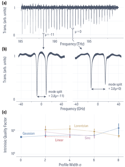
The mode-split and contra-propagative coupling strengths we present throughout the manuscript are extracted from linear measurements such as the one presented in Fig. 5(a). In the case of the TE mode spectroscopy ranging from about 185 THz and 198 THz, the continuously tunable laser (CTL) is calibrated by simultaneously probing a tri-gas cell. Using the NIST calibration of \ceH12CN, 13\ceCO and 13\ceCO absorption lines we are able to accurately retrieve the wavelength of the transmission scan. We define the normalized mode number relative to the centered mode-splitting, which is retrieved with a single-mode splitting device (i.e. sine modulation of the ring width), and each mode is then indexed from this mode, allowing to retrieve the coupling from the mode splitting [Fig. 5(b)]. From this linear spectroscopy data, we also extract the intrinsic and the coupling quality factors through a simple coupled mode-theory model BorselliOpt.ExpressOE2005 . In Fig. 5(c), we present the average intrinsic quality factor for the four modal coupling envelopes presented in Fig. 3 for the TE polarization, with the nominal spectral size for each envelope, with the error bar representing the standard variation of Q over the different modes measured. The intrinsic quality factor does not seem to be impacted and remains close to a million with little variation over the different modes, although the modulation of the ring width is extremely local (see the following section). The excess radiation losses induced by the photonic crystal modulation can therefore be concluded to be minimal in our system.
Fabrication details
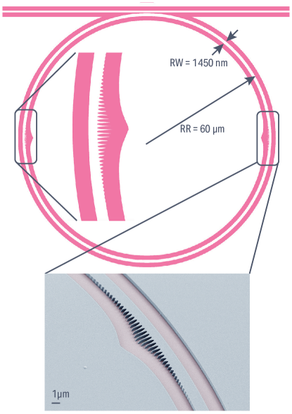
The microresonators are made of a 440 nm thick stoichiometric \ceSi3N4 grown via low pressure chemical vapor deposition with a 7:1 ammonia/dichlorosilane gas ratio, on top of thermal \ceSiO2. The layout presented in Fig. 6 is patterned using electron-beam lithography. The ring and waveguide are then etched using a reactive ion etching method. The facets are clad with \ceSiO2 while the rings are still air-clad thanks to a lift-off process of the \ceSiO2. The chips are then diced and polished for testing.
Data availability
The data that supports the plots within this paper and other findings of this study are available from the corresponding authors upon reasonable request.
Code availability
The LLE code to study the microcomb dynamics is a modified version of pyLLE MoilleJ.RES.NATL.INST.STAN.2019 which can be made available upon reasonable request.
References
- (1) Stern, B., Ji, X., Okawachi, Y., Gaeta, A. L. & Lipson, M. Battery-operated integrated frequency comb generator — Nature. Nature 562, 401–405 (2018).
- (2) Spencer, D. T. et al. An optical-frequency synthesizer using integrated photonics. Nature 557, 81–85 (2018).
- (3) Li, Q. et al. Stably accessing octave-spanning microresonator frequency combs in the soliton regime. Optica 4, 193 (2017).
- (4) Pfeiffer, M. H. P. et al. Octave-spanning dissipative Kerr soliton frequency combs in Si3N4 microresonators. Optica 4, 684–691 (2017).
- (5) Brasch, V. et al. Photonic chip–based optical frequency comb using soliton Cherenkov radiation. Science 351, 357–360 (2016).
- (6) Nazemosadat, E. et al. Switching dynamics of dark-pulse Kerr frequency comb states in optical microresonators. Physical Review A 103, 013513 (2021).
- (7) Ye, Z. et al. Integrated, Ultra-Compact High-Q Silicon Nitride Microresonators for Low-Repetition-Rate Soliton Microcombs. Laser & Photonics Reviews 16, 2100147 (2022).
- (8) Moille, G. et al. Ultra-broadband Kerr microcomb through soliton spectral translation. Nature Communications 12, 7275 (2021).
- (9) Shen, B. et al. Integrated turnkey soliton microcombs. Nature 582, 365–369 (2020).
- (10) Bruch, A. W. et al. Pockels soliton microcomb. Nature Photonics 15, 21–27 (2021).
- (11) Wang, C. et al. Monolithic lithium niobate photonic circuits for Kerr frequency comb generation and modulation. Nature Communications 10, 978 (2019).
- (12) Lee, S. H. et al. Towards visible soliton microcomb generation. Nature Communications 8, 1295 (2017).
- (13) Moille, G., Westly, D., Simelgor, G. & Srinivasan, K. Impact of the precursor gas ratio on dispersion engineering of broadband silicon nitride microresonator frequency combs. Optics Letters 46, 5970–5973 (2021).
- (14) Moille, G., Westly, D., Simelgor, G. & Srinivasan, K. Towards Lower Repetition Rate and Visible Wavelength Microresonator Frequency Combs for Optical Atomic Clocks. In CLEO 2022, SW4H.6 (San Jose, California, 2022).
- (15) Anderson, M. H. et al. Zero dispersion Kerr solitons in optical microresonators. Nature Communications 13, 4764 (2022).
- (16) Anderson, M. H. et al. Photonic chip-based resonant supercontinuum via pulse-driven Kerr microresonator solitons. Optica 8, 771 (2021).
- (17) Dorche, A. E. et al. Advanced dispersion engineering of a III-nitride micro-resonator for a blue frequency comb. Optics Express 28, 30542–30554 (2020).
- (18) Moille, G., Li, Q., Kim, S., Westly, D. & Srinivasan, K. Phased-locked two-color single soliton microcombs in dispersion-engineered Si3N4 resonators. Optics Letters 43, 2772–2775 (2018).
- (19) Kim, S. et al. Dispersion engineering and frequency comb generation in thin silicon nitride concentric microresonators. Nature Communications 8 (2017).
- (20) Liu, J. et al. High-yield, wafer-scale fabrication of ultralow-loss, dispersion-engineered silicon nitride photonic circuits. Nature Communications 12, 2236 (2021).
- (21) Lu, X., Rogers, S., Jiang, W. C. & Lin, Q. Selective engineering of cavity resonance for frequency matching in optical parametric processes. Applied Physics Letters 105, 151104 (2014).
- (22) Black, J. A. et al. Optical-parametric oscillation in photonic-crystal ring resonators. Optica 9, 1183–1189 (2022).
- (23) Lu, X., Chanana, A., Zhou, F., Davanco, M. & Srinivasan, K. Kerr optical parametric oscillation in a photonic crystal microring for accessing the infrared. Optics Letters 47, 3331–3334 (2022).
- (24) Stone, J. R. et al. Wavelength-Accurate Nonlinear Conversion through Wavenumber Selectivity in Photonic Crystal Resonators. arXiv 2212.05695 (2022).
- (25) Yu, S.-P. et al. Spontaneous pulse formation in edgeless photonic crystal resonators. Nature Photonics 15, 461–467 (2021).
- (26) Lu, X., McClung, A. & Srinivasan, K. High-Q slow light and its localization in a photonic crystal microring. Nature Photonics 16, 66–71 (2022).
- (27) Lu, X., Rao, A., Moille, G., Westly, D. A. & Srinivasan, K. Universal frequency engineering tool for microcavity nonlinear optics: Multiple selective mode splitting of whispering-gallery resonances. Photonics Research 8, 1676–1686 (2020).
- (28) Moille, G. et al. Engineering of Modal Coupling of Counter-Propagating Waves for Multi-Color Dissipative Kerr Soliton Operation. In Conference on Lasers and Electro-Optics (2022), Paper STh2F.3, STh2F.3 (2022).
- (29) Kippenberg, T. J., Gaeta, A. L., Lipson, M. & Gorodetsky, M. L. Dissipative Kerr solitons in optical microresonators. Science 361, eaan8083 (2018).
- (30) Lugiato, L. A. & Lefever, R. Spatial Dissipative Structures in Passive Optical Systems. Physical Review Letters 58, 2209–2211 (1987).
- (31) Hansson, T., Modotto, D. & Wabnitz, S. Dynamics of the modulational instability in microresonator frequency combs. Physical Review A 88, 023819 (2013).
- (32) Chembo, Y. K. & Menyuk, C. R. Spatiotemporal Lugiato-Lefever formalism for Kerr-comb generation in whispering-gallery-mode resonators. Physical Review A 87, 053852 (2013).
- (33) Joannopoulos, J. D. (ed.) Photonic Crystals: Molding the Flow of Light (Princeton, 2008), 2nd ed edn.
- (34) Ji, X. et al. Compact, spatial-mode-interaction-free, ultralow-loss, nonlinear photonic integrated circuits. Communications Physics 5, 1–9 (2022).
- (35) Lee, S.-G. & Magnusson, R. Essential differences between TE and TM band gaps in periodic films at the first Bragg condition. Optics Letters 44, 4658 (2019).
- (36) Lu, X. et al. Highly-twisted states of light from a high quality factor photonic crystal ring. arXiv 2208.13075 (2022).
- (37) Wang, M. et al. Fractional Optical Angular Momentum and Multi-Defect-Mediated Mode Renormalization and Orientation Control in Photonic Crystal Microring Resonators. Physical Review Letters 129, 186101 (2022).
- (38) Fan, Z. & Skryabin, D. V. Soliton blockade in bidirectional microresonators. Optics Letters 45, 6446 (2020).
- (39) Moille, G. et al. Integrated buried heaters for efficient spectral control of air-clad microresonator frequency combs. APL Photonics 7, 126104 (2022).
- (40) Rao, A. et al. Towards integrated photonic interposers for processing octave-spanning microresonator frequency combs — Light: Science & Applications. Light: Science & Applications 10, 109 (2021).
- (41) Luo, R., Liang, H. & Lin, Q. Multicolor cavity soliton. Optics Express 24, 16777–16787 (2016).
- (42) Akhmediev, N. & Karlsson, M. Cherenkov radiation emitted by solitons in optical fibers. Physical Review A 51, 2602–2607 (1995).
- (43) Cherenkov, A. V., Lobanov, V. E. & Gorodetsky, M. L. Dissipative Kerr solitons and Cherenkov radiation in optical microresonators with third-order dispersion. Physical Review A 95, 033810 (2017).
- (44) Eggleton, B. J., de Sterke, C. M. & Slusher, R. E. Bragg solitons in the nonlinear Schrödinger limit: Experiment and theory. JOSA B 16, 587–599 (1999).
- (45) Wang, H. et al. Dirac solitons in optical microresonators. Light: Science & Applications 9, 205 (2020).
- (46) Wang, Y. et al. Universal mechanism for the binding of temporal cavity solitons. Optica 4, 855 (2017).
- (47) Helgason, Ó. B. et al. Dissipative solitons in photonic molecules. Nature Photonics 15, 305–310 (2021).
- (48) Tikan, A. et al. Emergent nonlinear phenomena in a driven dissipative photonic dimer. Nature Physics 17, 604–610 (2021).
- (49) Helgason, Ó. B. et al. Power-efficient soliton microcombs. arXiv 2202.09410 (2022).
- (50) Huang, Q., Ma, K. & He, S. Experimental Demonstration of Single Mode- Splitting in Microring With Bragg Gratings. IEEE Photonics Technology Letters 27, 1402–1405 (2015).
- (51) de Goede, M. et al. Mode-splitting in a microring resonator for self-referenced biosensing. Optics Express 29, 346 (2021).
- (52) Brunetti, G., Olio, F. D., Conteduca, D., Armenise, M. N. & Ciminelli, C. Comprehensive mathematical modelling of ultra-high Q grating-assisted ring resonators. Journal of Optics 22, 035802 (2020).
- (53) Chen, B. et al. Integrated Optical Vortex Microcomb. arXiv 2212.07641 (2022).
- (54) Miao, P. et al. Orbital angular momentum microlaser. Science 353, 464–467 (2016).
- (55) Liu, Y. et al. Integrated vortex soliton microcombs. arXiv 2212.07639 (2022).
- (56) Borselli, M., Johnson, T. J. & Painter, O. Beyond the Rayleigh scattering limit in high-Q silicon microdisks: Theory and experiment. Optics Express 13, 1515–1530 (2005).
- (57) Moille, G., Li, Q., Xiyuan, L. & Srinivasan, K. pyLLE: A Fast and User Friendly Lugiato-Lefever Equation Solver. Journal of Research of the National Institute of Standards and Technology 124, 124012 (2019).
- (58) Lucas, E., Yu, S.-P., Briles, T. C., Carlson, D. R. & Papp, S. B. Tailoring microcombs with inverse-designed, meta-dispersion microresonators. arXiv 2209.10294 (2022).
Acknowledgements
The authors thank Sashank Shridar and Yi Sun for their valuable input. The authors acknowledge funding from the DARPA APHI and NIST-on-a-chip programs.
While preparing the manuscript, we have been made aware of Ref.LucasArXiv2022 that has some similarities to our approach. Our work goes beyond the regime of relatively small mode splittings to theoretically and experimentally treat the 100 GHz shifts needed for broadband dispersion engineering and multi-color soliton formation.
Author contributions
G.M. led the project, designed the ring resonators, conducted the experiments, and helped develop the theoretical framework. X.L and J.S. helped with the design, D.W fabricated the devices. G.M. and K.S. wrote the manuscript with input from all authors. All the authors contributed and discussed the content of this manuscript.
Competing Interests
The authors declare no competing interests.