Feed rotation corrections for antennas having beam waveguide mounts.
R. Dodson, M. Rioja
1 Abstract
We report on the development of new code to support the beam waveguide antenna mount types in AIPS, which will allow polarisation analysis of observations made using these antennas. Beam Wave-guide antennas in VLBI are common in communication antennas that have been repurposed (e.g. Warkworth, Yamaguchi).
The mount type affects the differential phase between the left and the right hand circular polarisations (LHC and RHC) for different points on the sky. We demonstrate that the corrections for the Warkworth beam wave guide antenna can be applied.
2 Telescope Mounts
Mount types are a combination of the focus position and the drive type. In Radio Astronomy there are six more or less commonly used focus positions, and three drive types.
2.1 Focus positions
Radio telescopes use a much more limited set of focus positions compared to optical telescopes. Figure 1 indicates where the focii are. Here we list them, along with examples of the codes for telescopes which use them (in brackets). Images of these are shown in figure 1 of eLBA memo 9.
-
•
Prime focus (PKS/MED). Focus at the site of the secondary mirror (sub-reflector).
-
•
Cassegrain focus (VLBA/most). Focus after the secondary (hyperboloid) mirror.
-
•
Gregorian focus (EFF). Prime Focus before the secondary (ellipsoid) mirror, secondary focus after the secondary mirror.
-
•
Folded Cassegrain focus (CED). Focus bolted to the elevation axis, after the tertiary mirror.
-
•
Reduced Nasmyth focus (JCMT). Focus on the elevation axis, but bolted to the azimuth floor, after the tertiary mirror.
-
•
Full Nasmyth focus (PV/YEB40). Focus bolted to the azimuth axis floor, after the forth mirror.
-
•
Beam Wave Guide focus (WARK/YAMA). Focus bolted to the floor of the antenna support structure, after the fifth (or more) mirror.
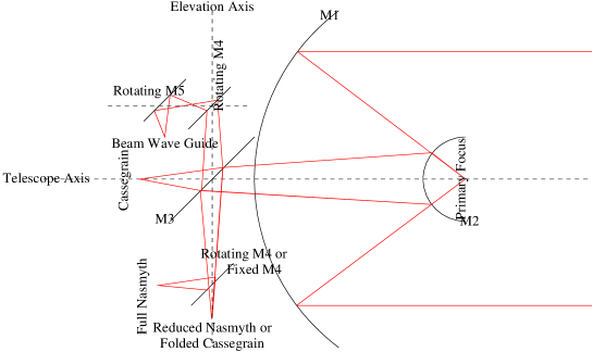
Fixed mirrors after the forth, in a Nasmyth system, swap the mount type between the equivalent of a reduced and full Nasmyth, so that any system with an odd number of mirrors is a ‘reduced’ and an even number of mirrors is equivalent to a ‘full’ Nasmyth system in our context. In a similar fashion the expression for a folded Cassegrain and Prime focus solutions are essentially the same, being either one or three reflections from the on-sky view. The difference between a Cassegrain and a Gregorian image is a rotation (of 180o), so these types are degenerate after the absolute position angle calibration. Furthermore at the correlator, the ‘on sky’ left or right is combined with the same to produce the parallel hand output. This is effectively the same as adding another mirror to the optical chain for those optics with an odd number of mirrors. For all expected cases, therefore, we will be correlating either Cassegrain, Nasmyth or Beam WaveGuide foci, combined with the drive type of the antenna. Nasmyth is Right or Left handed, depending on the orientation of M3. Likewise M5 can be Right or Left handed, but in all cases we have seen they are R where M3 is L, and vice versa.
2.2 Drive configuration
There are three drive configurations used in VLBI. This also effects the rotation of the feeds as seen from the sky.
-
•
HA-DEC (WST), for Hour Angle – Declination. Also called equatorial. It produces no change of feed angle as the source passes across the sky. As HA-DEC mounts require an asymmetrical structural design they are unsuited to the support of very heavy structures. Their advantage is that motion is required in only one axis to track an object as Earth rotates.
-
•
ALT-AZ (VLBA/most), for Altitude – Azimuth. Also called Az-El. It rotates the telescope pointing by the parallactic angle as the source passes across the sky. It is the most common variety of Radio telescope mount. It is symmetric so can support very large antennae, but at the zenith small angular changes on the sky can require very large angular changes in the azimuth angle. This effect is call the ‘keyhole’.
-
•
EW (HOB), for East – West. It rotates the telescope by the co-parallactic angle as the source passes across the sky. An EW mount places the focus very high, therefore it is prone to flexing and poor pointing. Their advantage is that they can track across the sky at high speeds and without gaps (i.e. it does not have a ‘keyhole’ at the zenith). They are primarily used for tracking Low Earth Orbit satellites.
The parallactic angle, sometimes called the position angle, of an object is the angle between the celestial pole (north or south depending on location), the object and the zenith (the point in the sky directly overhead). It is not to be confused for the same named angle which is also called the convergence angle. This is the difference in the angular direction to an object at a distance, from two points of view, i.e. the parallax. The expression for the parallactic angle as we use it is;
The co-parallactic angle is;
The Nasmyth angle is almost the same as the parallactic angle, but with the relative rotation of the forth mirror included;
The BWG angle is almost the same as the Nasmyth angle, but with the relative rotation of the fifth mirror included;
where is the hour angle, and the declination, of the source. is the latitude of the telescope, is the elevation and is the azimuth. As all BWG bring the focus back into the pedistal, the sign of and are opposite; in principle this does not need to be the case.
Each mirror adds a swap of polarisation from LHC to RHC. Therefore, in principle, the number of reflections before the horn is very important in any optical system, as each mirror also swaps the feed angle polarisation vector on the sky. However when the detected LHC or RHC polarisations are relabelled to represent the on-sky value, an effective mirror is added to produce the parallel or cross hand outputs. This means that only Cassegrain, Nasmyth or BWG models are required.
| Mount Number | ||
| Focus and Drive | Label | AIPS |
| Cassegrain and Alt-Az | ALAZ | 0 |
| Any and Equatorial | EQUA | 1 |
| Any and Orbiting | ORBI | 2 |
| New mount types | ||
| Prime focus and EW | EW- - | 3 |
| Right hand Naysmyth and Alt-Az | NS-R | 4 |
| Left hand Naysmyth and Alt-Az | NS-L | 5 |
| Right hand BWG and Alt-Az | BW-R | 6 |
| Left hand BWG and Alt-Az | BW-L | 7 |
3 The Beam Wave Guide configuration
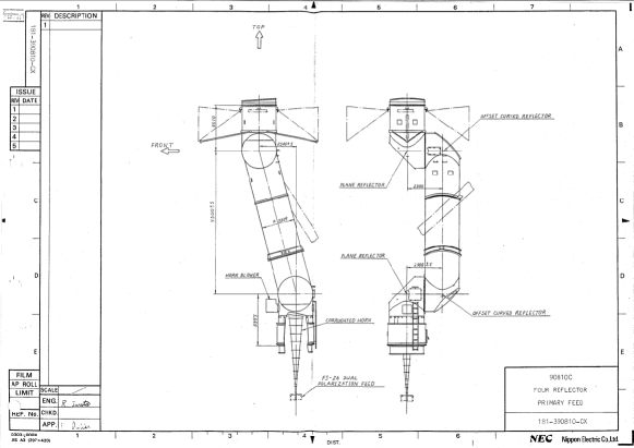
The feed in a beamed wave guide system sits on the floor on the pedestal, thus avoiding movement and related issues. The image of the sky has to pass over two rotating mirrors, here assumed to be M3 and M5. Other static mirrors can and often are introduced, but the only fact that is important is the rotational behaviour of the mirrors that move. I.e. for a “folded cassagrain” (only Ceduna to our knowledge) the M3 rotates with the elevation axis, so there is no extra term introduced and this behaves as a Cassegrain (if the mount in Alt-Az). Therefore the difference between the instrumental polarisation angle of a BWG mount and the parallactic angle is plus or minus the elevation angle and minus or plus the azimuthal angle. This assumes that the BWG directs the image of the sky back to the central axis; if it does not the sign of the Azimuth angle changes.

Appendix A Antenna Table Example
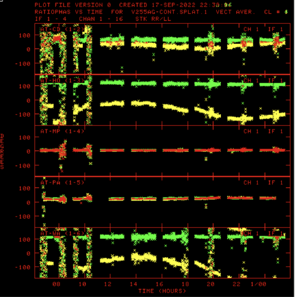
This is the table from V255AG after correction using AIPS 31DEC22 with update UPD20221017.064133.
File=V255AG-CONT .SPLAT . 1 An.ver= 1 Vol= 1 User= 255
AT BX= -4751640.5462 BY= 2791700.2552 BZ= -3200490.1824 Mount=ALAZ
CD BX= -3753443.6701 BY= 3912709.8121 BZ= -3348066.5042 Mount=ALAZ
HO BX= -3950237.6040 BY= 2522347.7251 BZ= -4311561.6218 Mount=EW
MP BX= -4682769.8739 BY= 2802618.8436 BZ= -3291758.3473 Mount=ALAZ
PA BX= -4554232.7144 BY= 2816758.8501 BZ= -3454034.7194 Mount=ALAZ
WA BX= -5115425.85 BY= 477880.2434 BZ= -3767042.0 Mount=BWR
Running CLCOR on an array including Hobart (co-parallactic) and Warkworth (BWG right handed) you get:
CLCOR1: Task CLCOR (release of 31DEC22) begins
CLCOR1: Copied CL file from vol/cno/vers 1 1 1 to 1 1 9
CLCOR1: CL version input 1 output 9
CLCOR1: Using CO-PARALACTIC ANGLES for antenna 3
CLCOR1: BeamWaveGuide formula for antenna 6
CLCOR1: 3209 Records modified
CLCOR1: Appears to have ended successfully
Appendix B Recommendations for calibration of polarisation observations
Many references have covered this, but here I wish to clearly layout the important steps in AIPS and the consequences of the tasks.
-
•
TABED options: INE ’AN’; OPTY ’repl’; APARM 5 0 0 4 4 6 and KEYV 6 0
Replaces the MNTSTA type of antenna 6 (Wa) with value 6 (for a right handed BWG, as is the case for Warkworth). -
•
CLCOR options: CLCORP 1 0 and OPC ’pang’
Calculates the phase correction for the listed mount types. -
•
FRING options: CALS ’prime_cal’; APARM(3)=0 and APARM(5)=0
Finds the independent delays and combined rates and phases for the calibrator. Now the RR/LL phase will be constant. -
•
CALIB options: CALS ’prime_cal’; SOLMODE ’P’; APARM(3)=0 and APARM(5)=0
Finds the independent rates and phases for the calibrator. Now the RR, LL and RR/LL phases will be zero. One may wish to use only one scan on the prime calibrator. -
•
VLBACPOL this procedure finds the delays between left and right hand for the reference antenna. If PCAL (or something similar) is used the delay between left and right should be zero.
-
•
FRING options: CALS ’target’,’calib’; APARM(3)=1 and APARM(5)=1
Finds the rates and combined phases for the target. -
•
CALIB options: CALS ’calib’; SOLMODE ’A&P’; APARM(3)=1 and APARM(5)=1
Produces a well calibrated version of the target which can be imaged. -
•
IMAGR Deconvolve this with, either a few model components, or clean it and then box up the clean components into a few regions (with CCEDT), and use it for the next stage.
-
•
LPCAL options: CALS ’calib’; in2na ’calib’ and in2c ’icln’
Does the polarisation calibration on the target, using the cleaned model. -
•
CALIB options: CALS ’target’; SOLMODE ’A&P’; DOPOL 2; APARM(3)=1 and APARM(5)=1
Calibrates the target using the polarisation solutions. -
•
IMAGR Image the source in I, Q and U. The sum of the fluxes (total and polarised) should compare to the lower resolution (VLA or ATCA) values. The correction is , for each IF.
-
•
CLCOR options: CLCORP stokes ’L’ and OPC ’polr’
Rotates the D-terms to match the calibration value of .
If this recipe is not followed the solutions for the L and R hand polarisations are independent. This is not a problem if there is sufficient signal to noise.
Appendix C A list of the changes to classic AIPS 31DEC22
A summary of the files that need to be changed:
-
•
PARANG.FOR: all mount types now supported
-
•
PARACO.FOR: all mount types now supported (PARACO is a new function almost the same as PARANG)
-
•
PRTAN.FOR: Add mount names
-
•
CLCOR.FOR: in ANAXIS allow all mount types
-
•
DFCOR.FOR: in ANAXIS allow all mount types
-
•
SNPLT.FOR: does not use PARANG, so mount types added
-
•
DTSIM.FOR: (in ORIENT) does not use PARANG, so mount types added
-
•
DTSIM.FOR: (in GETBAS) allow all mount types