11email: sugiyama@heal.phy.saitama-u.ac.jp
Vibration characteristics of a continuously rotating superconducting magnetic bearing and potential influence to TES and SQUID
Abstract
We measured the vibration of a prototype superconducting magnetic bearing (SMB) operating at liquid nitrogen temperature. This prototype system was designed as a breadboard model for LiteBIRD low-frequency telescope (LFT) polarization modulator unit. We set an upper limit of the vibration amplitude at 36 at the rotational synchronous frequency. During the rotation, the amplitude of the magnetic field produced varies. From this setup, we compute the static and AC amplitude of the magnetic fields produced by the SMB magnet at the location of the LFT focal plane as 0.24 G and G, respectively. From the AC amplitude, we compute TES critical temperature variation of K and fractional change of the SQUID flux is . The mechanical vibration can be also estimated to be N at the rotation mechanism location.
Keywords:
Cosmic Microwave Background, Half-wave plate polarimetry, Cryogenics1 Introduction
The use of a continuously rotating half-wave plate (HWP) is a standard approach for cosmic microwave background (CMB) polarimetry to overcome detector noise. Existing and upcoming CMB polarization experiments, including EBEX, POLARBAER, LSPE, Simons Observatory, employ HWPs with superconducting detector arraysebex_hwp ; polarbear_hwp ; lspe_hwp ; so_hwp . Typically, the two sub-systems, HWP and detector array, are developed separately and integrated in the receiver’s cryostat. Although a continuously rotating HWP is introduced to improve the polarimeter performance, a mechanically rotating element can introduce unexpected interference to a sensitive superconducting detector array. Such effects are usually identified and investigated only after integration resulting in delays of the scientific observations. When it comes to a space mission, these delays during the integration phase can be critical. Thus, detailed planning for a campaign of detailed characterization and performance forecasting is essential.
One potential source of interference is due to vibrations of the continuously rotating HWP. Mechanical vibrations propagating from the HWP to the detector system can affect detector noise and focal plane temperature stability. A cryogenically compatible HWP rotational mechanism employs a superconducting magnetic bearing (SMB). The rotor consists of a ring-shaped permanent magnet, hence its vibration can affect the detector system via magnetic coupling. Finally, mechanical motions other than the expected rotation can affect the incident radiation.
We study the vibration properties of a continuously rotating HWP supported by a SMB. There has been little experimental investigation of the vibration amplitude of a SMB rotor designed for CMB polarimetry. Hull et al. reported measurements of the vibration amplitude of a SMB rotor hull with a rotor diameter of about 35 mm. We report on the use of a Hall sensor to monitor the vibration via the change of magnetic field from the rotor magnet. This is a useful method to monitor the characteristic vibration frequency but not the physical displacement amplitude due to an extra complex calibration step sakurai_magcal .
LiteBIRD is the second L-class mission of ISAS/JAXA and its science goal is to probe the inflationary B-modes. The baseline configuration employs a continuously rotating HWP and transition-edge sensor (TES) bolometer arrays lb_ptep_arxiv ; litebird . The work reported here is part of developing an SMB-based polarization modulator for LiteBIRD. In this paper we focus on characterizing the vibration properties of the SMB rotational mechanism and discuss their potential impact on the detector system. We also discuss future modeling of the impact of vibrations on the focal plane.
2 Experiment
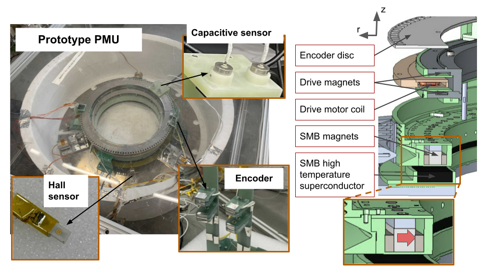
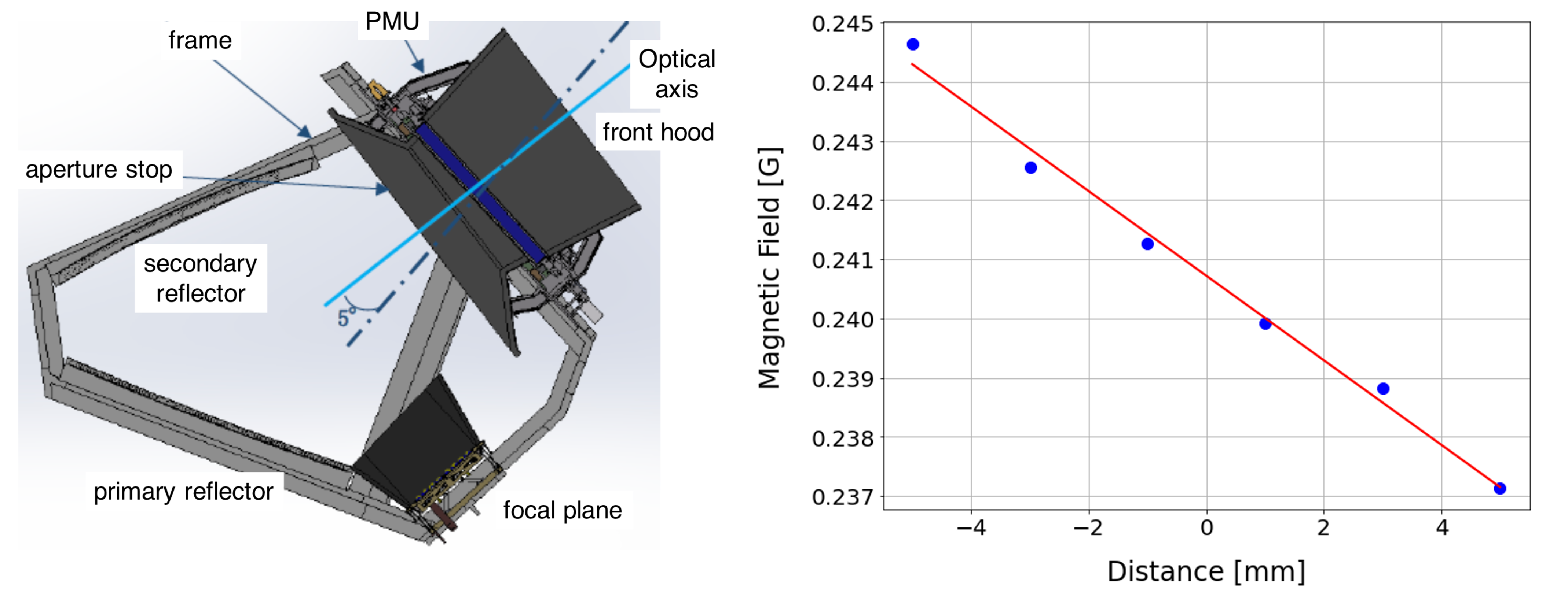
Figure 1 shows the breadboard model of LiteBIRD LFT HWP rotational mechanism, which is scaled to about 0.7:1 with respect to the flight model. The rotor consists of a ring array of segmented magnets that is radially magnetized as shown in Figure 1. The inner radius of the rotor magnet is 203 mm, the outer radius is 215 mm, and the thickness is 14 mm. Due to its large diameter, the rotor magnet is segmented into 32 magnets. The stator consists of segmented YBCO high temperature superconductor array. The 18 arc-shape bulk YBCO tiles form a ring shape with a diameter of 400 mm. The rotor is driven by a contactless ac motor. The rotor magnets have alternating poles, and an array of coils is placed in the stator to drive the rotor. Detailed descriptions of each component can be found in Sakurai et al. lft_pmu . The rotation of the rotor is monitored by two optical encoders 111Hamamatsu, model number: L9337-01 and S2386-18L used in combination with a 128-slots encoder disk mounted on the rotor. Axial displacement of the encoder disk is monitored by a capacitive sensor222Capacitec, model number: HPC-375E. We also placed a Hall sensor333Lakeshore, model number: BHT-921 between the rotor and the stator.
Before cooling the stator, the rotor is held by three cryogenic holder mechanisms at a distance of 5 mm from the stator. In order to test the system we submerge the stator superconductors in liquid nitrogen (LN2). Once the superconductors are thermalized to LN2 temperature, the cryogenic holder mechanisms release the rotor. Due to flux pinning the rotor is free to levitate and rotate in azimuth. The liquid nitrogen level is kept below the level of the rotor to reduce friction. The rotor is driven by an ac motor at a constant rotational frequency of 1 Hz for 10 minutes. We limit the time duration of the data acquisition to maintain nearly the same LN2 level. The data from the Hall and capacitive sensors are recorded simultaneously to correlate them. The capacitive sensor is calibrated separately prior to the measurements. Thus, we apply a calibration constant to convert the output voltage from the capacitive sensor to the rotor displacement in units of length.
3 Results
|
|
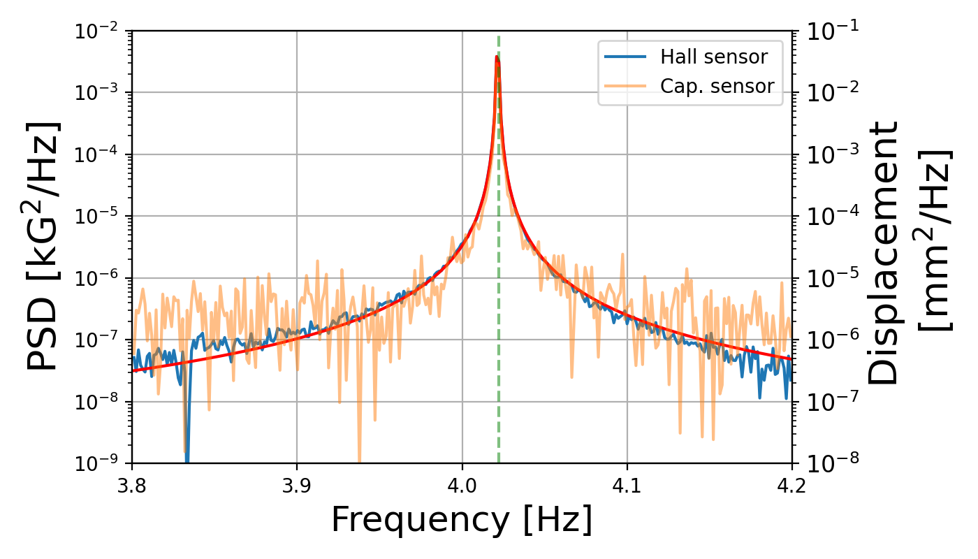
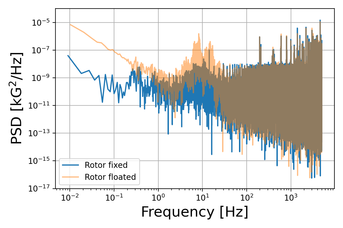
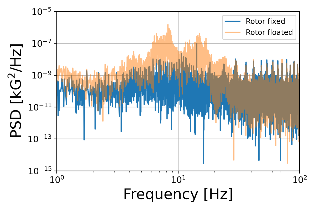
Fig. 2 shows the power spectrum density (PSD) of the magnetic field measured by the Hall sensor for two cases: (1) rotor gripped by the cryogenic holders, and (2) rotor levitated freely without rotation. We can identify two broad peaks at around 8 Hz and 15 Hz and also minor peaks below and above the two peaks present only when the rotor is levitated. These peaks correspond to natural frequencies in the radial and axial displacement and possibly other modes due to the nature of the segmented magnet array and YBCO array. The main two peaks are consistent with previously reported peak locations h_v_vibration . We also observe a series of peaks above 20 Hz in both gripped and levitating cases. We attribute these to spurious effects due to the evaporation of LN2 in the vicinity of the Hall sensor, and thus we discard these peaks in both cases. Furthermore, the Hall sensor is read by a Lakeshore Gauss meter which filters above 400 Hz, and thus we do not investigate the cause of higher frequency peaks beyond this cut-off frequency. We rely on the Hall sensor because the sensitivity of the capacitive sensor is not appropriate to detect nearly zero displacement during levitation.
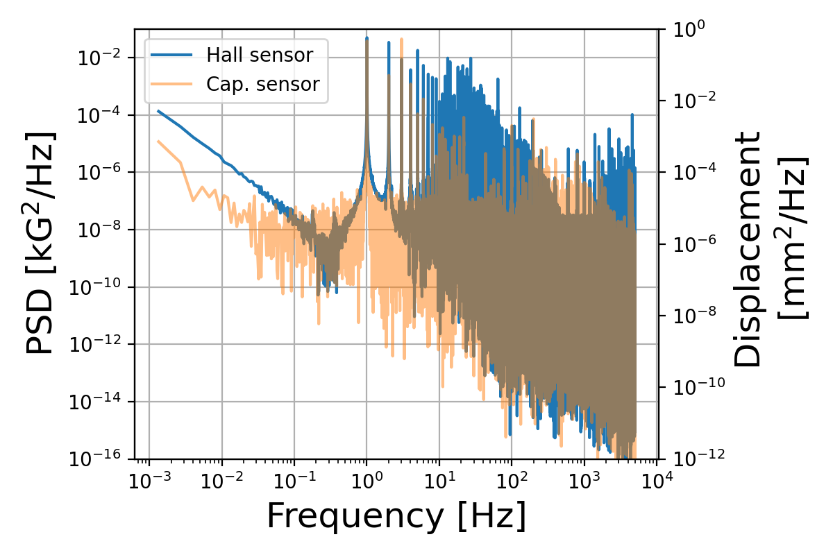
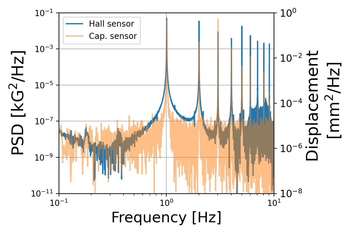
Fig. 3 show PSDs of the Hall and capacitive sensors when the rotor is spinning at 1 Hz. Both PSDs show distinctive peaks at the rotational frequency and its harmonics. The most prominent peak in the capacitive sensor PSD is at 1 Hz. From this measurement we find a corresponding physical displacement amplitude at 1 Hz of 36 . This value corresponds to a change in physical distance between the capacitive sensor and the encoder disk. In principle, we may be measuring the deformation of the encoder disk in the axial direction even though the SMB rotor rotates with a perfect stiffness. In this paper, we assume that the encoder disk is perfectly flat and interpret the measured displacement as the amplitude of the axial rotor vibration. Thus, we treat this number as an upper limit of the axial vibration amplitude.
Figure 4 shows the peak profile of the fourth harmonic. The shape is consistent with Lorentzian, i.e. a power of forced oscillation with an attenuation. The corresponding width is parameterized by a Q-value equal to .
4 Discussion
In this section we discuss the potential effects of the HWP vibration on the TES detectors on the focal plane. We use the LiteBIRD LFT configuration to define the relative position between the HWP and the focal plane sekimoto . We also assume the amplitude of the vibration to have a maximum amplitude of 36 m. We use this value for all vibration modes which we discuss in the following sections.
 |
4.1 Varying magnetic field
We estimate the magnetic field at the focal plane due to a presence of the SMB rotor magnet at the aperture stop, dc field, and a displacement of the rotor magnet, ac field, by using a commercially available finite element magnetic field simulation software, JMAG jmag . We find the dc and ac variations of the magnetic field in the focal plane of 0.24 G and G in amplitude, respectively. Detailed characterizations of the magnetic field susceptibility for LiteBIRD TES bolometers are in progress. Therefore, we use literature values for the magnetic field susceptibility of ground-base experiments TESes. Vavagiakis et al. reported a quadratic relationship between the critical temperature, , and the applied magnetic field, vavagiakis . The highest sensitivity coefficient found in this study was measured for MoCu based TES designed for ACTpol, and corresponds to K/G2. Due to the small applied magnetic field, we expand this quadratic form by the Taylor expansion as This approach was taken in past studies toki_phd ; ghigna_ltd . As a result, we find K.
The TES array is typically read by a Superconducting QUantum Interference Device (SQUID) that is sensitive to magnetic fields. LiteBIRD plans to use a frequency domain digital multiplexing (DfMUX) readout system lb_ptep_arxiv ; ghigna_ltd . A similar system has been employed in past and ongoing CMB experiments ebex_hwp ; sptpol . The susceptibility of SQUIDs to external magnetic fields was investigated by Luker with a magnetic shield mlueker_thesis . We assume a similar magnetic shielding scheme. The reported relationship between the fractional flux change and the external ac magnetic field is . This results in a fractional flux . This test was carried out with a non-gradiometric base SQUID fabricated at NIST privatecommunication . The new-generation SQUIDs are gradiometric and should be less sensitive to external magnetic fields. Therefore, we report our result as an upper limit. Propagating the expected detector temperature fluctuations and SQUID responsivity variations to expected systematic uncertainties is left for future analysis.
4.2 Restoring force
When the rotor vibrates, mechanical vibrations can propagate to the detector system. A detailed propagation mechanism in a cryogenically cooled structure is complex and addressing this is beyond the scope of this paper. Nevertheless, we can identify a similar situation by comparing the rotor vibration to those from the mechanical cooler.
If we assume the vibrating rotor as a point-like mass supported by a spring, we can simply calculate the force required by the spring to realize this motion as
| (1) |
where is the rotor mass. Here is the vibration amplitude and is the vibration frequency. If we assume kg, m and Hz as representative values for this exercise, the resultant force is N. Sato et al. reported on the measured force produced by a space qualified 1K Joule Thomson cooler joule_thomson . The maximum value is found at the driving frequency of 40 Hz in the range N depending on the orientation and the cooler. The rotor vibration force estimated above is a factor of one or more smaller. Again, further assessment of implication of this value is left for future analysis.
5 Conclusions
As part of the development of the breadboard model of the SMB-based HWP rotation mechanism for LiteBIRD LFT, we have measured the displacement of the rotor by using a capacitive sensor. We identified rotation synchronous peaks in the axial displacement data during rotation tests at 1 Hz. If we assume that the largest peak at 1 Hz is purely due to axial vibrations, we obtain a corresponding amplitude of 36 m. From simulations we found that this displacement can generate an AC magnetic field of G amplitude at the focal plane. This corresponds to a prospective shift of of K if we adopt a magnetic field susceptibility from existing ground-based TES. We also estimated the effect on the SQUID to be . The mechanical vibration force due to this vibration is found to be N, which is a factor of one or more smaller than that from the 1K-JT cooler at the driving frequency of 40 Hz. The actual impact on the TES and focal plane temperature stability is yet to be investigated. This work is a part of an investigation of potential interference between the continuously rotating HWP and TES arrays for LiteBIRD LFT. While we investigated the source of the vibration experimentally, further studies are required to fully forecast the impact as noise and systematic effects through TES and SQUID.
Acknowledgements.
We acknowledge the World Premier International Research Center Initiative (WPI), MEXT, Japan for support through Kavli IPMU. This work was supported by JSPS KAKENHI Grant Numbers JP17H01125, 19K14732, 18KK0083, and JSPS Core-to-Core Program, A.Advanced Research Networks.Ethical statement Our study is not applicable to the compliance with Ethical Standards.
References
- (1) EBEX Collaboration, A. M. Aboobaker, P. Ade, D. Araujo, F. Aubin, C. Baccigalupi, C. Bao, D. Chap-man, J. Didier, M. Dobbs, C. Geach, W. Grainger, S. Hanany, K. Helson, S. Hillbrand, J. Hubmayr,A. Jaffe, B. Johnson, T. Jones, J. Klein, A. Korotkov, A. Lee, L. Levinson, M. Limon, K. MacDer-mid, T. Matsumura, A. D. Miller, M. Milligan, K. Raach, B. Reichborn-Kjennerud, I. Sagiv, G. Savini,L. Spencer, C. Tucker, G. S. Tucker, B. Westbrook, K. Young, and K. Zilic. The EBEX Balloon-borne Experiment: Optics, Receiver, and Polarimetry.The Astrophysical Journal Supplement, 239:7,November 2018.
- (2) C. A. Hill, A. Kusaka, P. Barton, B. Bixler, A. G. Droster, M. Flament, S. Ganjam, A. Jadbabaie,O. Jeong, A. T. Lee, A. Madurowicz, F. T. Matsuda, T. Matsumura, A. Rutkowski, Y. Sakurai, D. R.Sponseller, A. Suzuki, and R. Tat. A Large-Diameter Cryogenic Rotation Stage for Half-Wave Plate Polarization Modulation on the POLARBEAR-2 Experiment. Journal of Low Temperature Physics,193:851–859, December 2018.
- (3) B. Johnson et al., A Large-Diameter Hollow-Shaft Cryogenic Motor Based on a Superconducting Magnetic Bearing for Millimeter-Wave Polarimetry
- (4) P. Ade et al., The Simons Observatory: science goals and forecasts. Journal of Cosmology and Astroparticle Physics, 2019, February 2019
- (5) J. R. Hull, S. Hanany, T. Matsumura, B. Johnson, and T. Jones. Characterization of a high-temperature superconducting bearing for use in a cosmic microwave background polarimeter. Superconductor ScienceTechnology, 18:S1–S5, February 2005.
- (6) Y. Sakurai, T. Matsumura, N. Katayama, H. Kanai, T. Iida, “Development of a Cryogenic Remote Sensing Thermometer for CMB Polarization Experiment”, 29th IEEE International Symposium on Space THz Technology (ISSTT2018), Pasadena, CA, USA, March 26-28, 2018.
- (7) E. Allys et al., ”Probing Cosmic Inflation with the LiteBIRD Cosmic Microwave Background Polarization Survey”, arXiv preprint arXiv:2202.02773
- (8) M. Hazumi et al., ”LiteBIRD satellite: JAXA’s new strategic L-class mission for all-sky surveys of cosmic microwave background polarization”, SPIE proceedings, (2020).
- (9) Y. Sakurai et al., ”Breadboard model of polarization modulator unit based on a continuous rotating half-wave plate for low frequency telescope of litebird space mission”, SPIE Proceedings, (2020).
- (10) Y. Sakurai et al., ”Vibrational characteristics of a superconducting magnetic bearing employed for a prototype polarization modulator”, J. Phys, 871, (2017).
- (11) Y. Sekimoto et al., ”Concept Design of Low Frequency Telescope for CMB B-mode Polarization satellite LiteBIRD”, SPIE proceedings, (2020).
- (12) JSOL-Corporation,“JMAG : Simulation Technology for Electromechanical Design”, http://www.jmag-international.com/.
- (13) E. M. Vavagiakis, S. W. Henderson, K. Zheng, H.-M. Cho, N. F. Cothard, B. Dober, S. M. Duff, P. A. Gallardo, G. Hilton, J. Hubmayr, K. D. Irwin, B. J. Koopman, D. Li, F. Nati, M. D. Niemack, C. D. Reintsema, S. Simon, J. R. Stevens, A. Suzuki and B. Westbrook, “Magnetic Sensitivity of AlMn TESes and Shielding Considerations for Next-Generation CMB Surveys”, Journal of Low Temperature Physics volume 193, pages 288–297 (2018).
- (14) A. Suzuki, ”Multichroic Bolometric Detector Architecture for Cosmic Microwave Background Polarimetry Experiments”, PhD thesis. University of California, Berkeley, Jan. 2013.
- (15) T. Ghigna et al. (2020). Design of a testbed for the study of system interference in space CMB polarimetry. Journal of Low Temperature Physics, 199(3), 622-630.
- (16) J. E. Austermann et al. (2012). SPTpol: an instrument for CMB polarization measurements with the South Pole Telescope. Millimeter, Submillimeter, and Far-Infrared Detectors and Instrumentation for Astronomy VI, 8452.
- (17) M. Lueker, ”Measurements of Secondary Cosmic Microwave Background Anisotropies with the South Pole Telescope”, PhD thesis. University of California, Berkeley
- (18) Private communication.
- (19) Y. Sato et al., ”Development of 1K-class Joule–Thomson cryocooler for next-generation astronomical mission”, Cryogenics. 74, 47-54, (2016).
- (20) G. D’Alessandro et al., ”Systematic effects induced by Half Wave Plate precession into Cosmic Microwave Background polarization measurements”, Astronomy & Astrophysics, 627, (2019).