Gate-tunable Lifshitz transition of Fermi arcs and its nonlocal transport signatures
Abstract
One hallmark of the Weyl semimetal is the emergence of Fermi arcs (FAs) in the surface Brillouin zone that connect the projected Weyl nodes of opposite chirality. The unclosed FAs can give rise to various exotic effects that have attracted tremendous research interest. The configurations of the FAs are usually thought to be determined fully by the band topology of the bulk states, which seems impossible to manipulate. Here, we show that the FAs can be simply modified by a surface gate voltage. Because the penetration length of the surface states depends on the in-plane momentum, a surface gate voltage induces an effective energy dispersion. As a result, a continuous deformation of the surface band can be implemented by tuning the surface gate voltage. In particular, as the saddle point of the surface band meets the Fermi energy, the topological Lifshitz transition takes place for the FAs, during which the Weyl nodes switch their partners connected by the FAs. Accordingly, the magnetic Weyl orbits composed of the FAs on opposite surfaces and chiral Landau bands inside the bulk change its configurations. We show that such an effect can be probed by the nonlocal transport measurements in a magnetic field, in which the switch on and off of the nonlocal conductance by the surface gate voltage signals the Lifshitz transition. Our work opens a new route for manipulating the FAs by surface gates and exploring novel transport phenomena associated with the topological Lifshitz transition.
I introduction
In the last two decades, the research on novel topological materials has seen rapid progress, involving the discoveries of the topological insulators Qi and Zhang (2011); Hasan and Kane (2010); Kane and Mele (2005) and topological semimetals Armitage et al. (2018); Hasan et al. (2017); Wan et al. (2011); Zhang et al. (2017); Yu et al. (2017); Li et al. (2020); Burkov et al. (2011). The latter possess gapless energy spectra but nontrivial band topology, which can give rise to interesting effects stemming from both the bulk and surface states. According to the features of the band degeneracies, topological semimetals can be further classified into several types, such as Weyl semimetal (WSM), Dirac semimetal Wan et al. (2011); Armitage et al. (2018); Hasan et al. (2017) and nodal-line semimetal Burkov et al. (2011). As the counterparts of the massless Weyl and Dirac fermions in condensed matter physics, the quasiparticles with linear dispersion in the WSM and Dirac semimetals provide an interesting platform for exploring novel effects predicted by high-energy physics Xu et al. (2015a, b, c, 2016); Huang et al. (2016); Tamai et al. (2016); Deng et al. (2016); Yang et al. (2015); Jiang et al. (2017); Belopolski et al. (2016); Lv et al. (2015a); Murakami (2007); Huang et al. (2015a); Lv et al. (2015b); Adler (1969); Bell and Jackiw (1969). These effects are manifested as anomalous transport and optical properties which can be probed using a standard approach of condensed matter physics Zyuzin and Burkov (2012); Zhou et al. (2013); Burkov (2015); Aji (2012); Son and Spivak (2013); Chernodub et al. (2014); Ma and Pesin (2015); Zhong et al. (2016); Spivak and Andreev (2016); Hirschberger et al. (2016); Wang et al. (2016a).
The nontrivial band topology of the WSMs is embodied in the monopole charge (or Chern number of the Berry curvature field) carried by the Weyl nodes. According to the no-go theorem Nielsen and Ninomiya (1981, 1983), the Weyl nodes of opposite chirality must appear in pairs. The manifestation of the nontrivial band topology of the WSM is the unclosed Fermi arcs (FAs) spanning between Weyl nodes of opposite chirality projected into the surface Brillouin zone. The emergence of the FAs is a unique property of the WSMs, without any counterpart in high-energy physics, which can not only serve as the hallmark of the WSMs Huang et al. (2015a); Lv et al. (2015b); Xu et al. (2015a, b, c, 2016); Deng et al. (2016); Yang et al. (2015); Huang et al. (2016); Tamai et al. (2016); Jiang et al. (2017); Belopolski et al. (2016); Lv et al. (2015a), but also lead to several novel phenomena Armitage et al. (2018); Hasan et al. (2017); Wang et al. (2017); Lu and Shen (2017); Zheng and Zahid Hasan (2018); Huang et al. (2015b); Shekhar et al. (2015); Du et al. (2016); Zhang et al. (2016). Given that the FAs are the Fermi surface of the topological surface states, one might think that all its properties, especially how they connect pairs of Weyl nodes are completely determined by the band topology of the bulk states through the bulk-boundary correspondence. Therefore, it seems that the only way to modify the configurations of the FAs is to change the bulk properties of the WSMs.
Interestingly, recent research progress shows that the configurations of the FAs are quite sensitive to the details of the sample boundary Morali et al. (2019); Yang et al. (2019); Ekahana et al. (2020), which opens the possibility for manipulating the FAs through surface modifications. In particular, the topological Lifshitz transition Lifshitz et al. (1960) of the FAs can be induced by surface decoration Yang et al. (2019) or chemical potential modification Ekahana et al. (2020), which changes the sizes and shapes of the FAs, and especially, the way they connect pairs of Weyl nodes. The existing experiments show that FAs with different configurations can be realized in different samples Morali et al. (2019); Yang et al. (2019); Ekahana et al. (2020); Chen et al. (2018a, 2020); Zheng et al. (2021); Chen et al. (2021), but whether it is possible to continuously modify the FAs in a given sample remains an open question. It is of great interest to explore the possibility of manipulating the FAs by external fields, in which both continuous deformation and abrupt Lifshitz transition of the FAs can be achieved.
In this work, we show that the FAs of the WSMs can be continuously tuned by a surface gate voltage. Because the penetration length of the surface state depends on the in-plane momentum, the surface gate voltage acts unequally on these surface modes and induces a momentum-dependent potential energy, or effectively, an additional dispersion of the surface band Chen et al. (2020). As a result, a continuous deformation of the surface band and so the FAs can be achieved by simply tuning the gate voltage. It is shown that the existence of the saddle point in the surface band is responsible for the topological Lifshitz transition of the FAs. Specifically, the transition takes place when the saddle point coincides with the Fermi energy. At the same time, the Weyl nodes switch their partners that are connected by the FAs. A direct physical result is that the magnetic Weyl orbits composed of the FAs on opposite surfaces and the chiral Landau bands inside the bulk change their configurations. We show that such an effect can be probed by the nonlocal transport measurements in a magnetic field, in which the nonlocal current can be switched on and off by the gate voltage, thus providing a clear signature of the gate-voltage induced Lifshitz transition. In addition to the study on the effective model, we also calculate the surface electrostatic potential induced by the gate voltage in a specific WSM ZrTe using the first-principles calculations. It shows that the gate voltage can induce large potential energy which is sufficient for driving the Lifshitz transition of FAs. Our work not only uncovers the scenario of the Lifshitz transition of the FAs but also paves the way for its continuous manipulation by a surface gate voltage.
The rest of this paper is organized as follows: in Sec. II, we study the Lifshitz transition of the FAs based on both the continuous and lattice models. In Sec. III, we study the transport signatures of the surface gate induced Lifshitz transition. In Sec. IV, we discuss the experimental implementation of our proposal. Finally, we give a brief summary in Sec. V.
II Lifshitz transition of Fermi-arc induced by surface gate
We start with an effective model of WSM with four Weyl nodes Chen et al. (2020)
| (1) |
here is the velocity in the direction, and are parameters, are the Pauli matrices in the pseudo-spin space. The two bands are degenerate at four Weyl nodes with two FAs spanning between them respectively [cf. Fig. 2(a)]. Expanding around the Weyl points yields four Weyl equations .
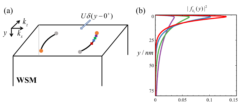
We are interested in the FA surface states, which can be solved under the open boundary condition in the direction. Consider a semi-infinite WSM that occupies the space of as shown in Fig. 1(a) and make the substitution in Eq. (1). For a given , Eq. (1) reduces to a 2D system in the - plane. It can be verified that for , such an effective 2D system possesses a nonzero Chern number with the chiral edge state that appears at its boundary. The edge states of all slices comprise the FA surface states. By solving the eigenequation under the open boundary condition , we obtain the dispersion and wave function of the surface state as
| (2) |
with , the spatial distribution function, the normalization coefficient, and .
Here, the key point is that the wave function of the surface state relies on the in-plane momentum . Specifically, wave function for different possesses unequal spatial spreading in the direction as shown in Fig. 1(b). This property opens a new route for manipulating FA surface states by a surface potential, which can be induced by a surface gate voltage. Consider an electric potential imposed on the surface of the WSM, which can be captured by . It induces an energy shift of the surface states, which can be evaluated by the overlap integral
| (3) |
The energy shift has a dependence and can be expanded as to the second order of with two constants for . Physically, such potential energy induces an effective surface dispersion and so the full energy of the surface states becomes
| (4) |
It means that the band shape of the surface states and then the FAs can be continuously tuned by the surface electric potential.
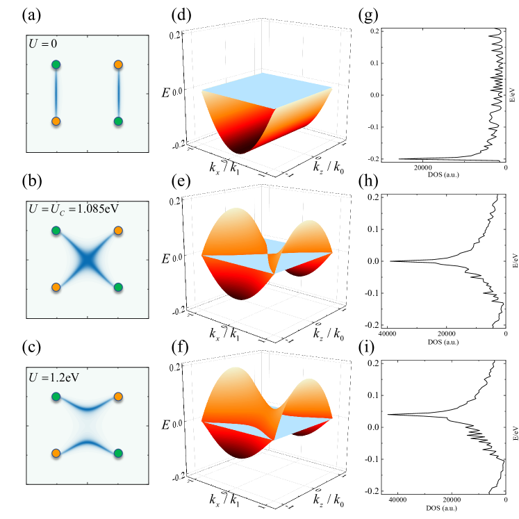
The interesting case occurs for , such that the coefficients before and have opposite signs. This means that the surface band bends towards opposite directions for and and becomes a hyperbolic paraboloid; see Figs. 2(e,f). The hyperbolic paraboloid surface band contains a saddle point, which is the key to understand the Lifshitz transition of the FAs. Setting the Fermi energy to zero, the FAs defined by the intersection curves between the surface band and Fermi surface undergo continuous modifications as the surface potential increases. The critical point for the Lifshitz transition takes place when the saddle point of the surface band lies exactly at the Fermi energy [cf. Fig. 2(e)], where the two FAs cross each other [cf. Fig. 2(b)]. As increases further, the saddle point is lifted above the Fermi energy and accordingly, the two FAs split again but change their way connecting the Weyl nodes [cf. Figs. 2(c,f)].
In addition to the analysis based on the continuous model, we investigate the effect of the surface potential on the FAs by the lattice model of Eq. (1). By substituting , and performing the partial Fourier transformation in the directions, we obtain
| (5) |
with the lattice constant and the two-component Fermi operator. An onsite potential is introduced to the outmost layer () of the lattice. Solving the effective 1D chain in the direction under the open boundary condition for each in-plane momentum yields the surface states. The surface bands for different electrostatic potential are plotted in Figs. 2(d)-(e). As expected, a surface potential can induce a severe deformation of the surface band, and most importantly, a saddle point emerges. For our parameters, the critical value of for Lifshitz transition is eV. The FAs can be revealed by the spectral function at the Fermi energy () with the surface Green’s function defined as
| (6) |
where is the surface component () of the eigenvector corresponding to the -th eigenvalue . The configurations of FAs in Figs. 2(a)-(c) are consistent with those of the surface bands in Figs. 2(d)-(f).
We have established the relation between the topological Lifshitz transition of the FAs and the underlying saddle points in the surface band, the latter indicating the existence of the van Hove singularity in the density of states (DOS) of the surface band. Therefore, the Lifshitz transition of the FAs indicates there exists the van Hove singularity at the Fermi energy. In Figs. 2(g-i), we plot the DOS calculated by . One can see that the energy of the van Hove singularity tracks that of the saddle point and equals the Fermi energy at the critical point of Lifshitz transition. Given that a variety of physical effects such as the enhancement of electron-electron interaction and the disturbance of many-body ground states Fleck et al. (1997); Rice and Scott (1975); Gonzalez (2008) are closed related with the van Hove singularity of the band, our work opens the possibility to realize interesting effects in the surface states of the WSM by the surface gate induced Lifshitz transition.
III Transport signatures of Fermi-arc Lifshitz transition
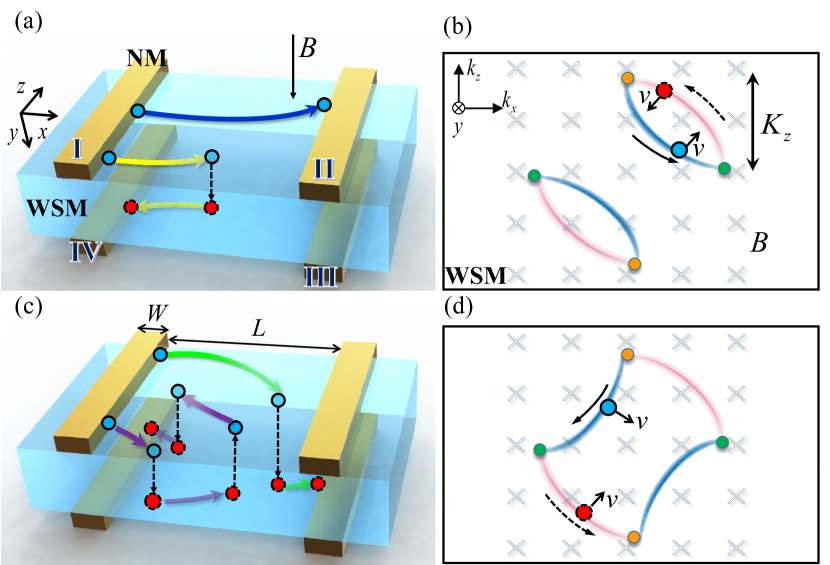
In this section, we investigate quantum transport in the device sketched in Fig. 3(a) under a magnetic field and show that the nonlocal conductance can provide a decisive signature of the Lifshitz transition of the FAs. The device is fabricated by depositing multiple strip electrodes (I-IV) on both the top and bottom surfaces of the WSM; see Fig. 3(a). General orientations of the FAs and the stripe electrodes are considered. Without loss of generality, we set the normal of the stripe electrodes to the direction and perform a rotation to the WSM or the Hamiltonian (1) by an angle about the axis, or explicitly, with . Accordingly, the configurations of the FAs shown in Fig. 2 undergo the same rotation; see Figs. 3(b,d). The stripe electrodes are just normal metals which can be described by the effective Hamiltonian as with the parameter determined by the effective mass and the chemical potential. We here focus on the surface transport with a negligible density of the bulk states and so set the chemical potential of the WSM to zero for simplicity.
Consider an electron injected from electrode I into the surface of the WSM. Without a magnetic field, it propagates straightforwardly into electrode II. Interesting situations take place when a magnetic field is imposed in the direction. Due to the Lorentz force, electrons are driven to slide along the FAs; see pictures in the momentum space [Figs. 3(b,d)] and the corresponding curved trajectories in the real space [Fig. 3(a,c)]. Because the FAs are terminated at the Weyl nodes, a closed loop for electron transport is composed of the FAs on both surfaces and the chiral Landau bands inside the bulk, so-called the Weyl orbit Potter et al. (2014). As a result, the trajectory of an incident electron is completely determined by the configuration of the Weyl orbit. As discussed in the previous section, a surface gate deposited on the top surface can modify the FAs therein, while the chiral Landau band and the FAs on the bottom surface are unaffected. A direct result is that the Weyl orbit possesses distinctive configurations and topology before and after the Lifshitz transition of the top FAs; compare Fig. 3(b) and Fig. 3(d).
For the Weyl orbit in Fig. 3(b), electrons injected from electrode I may have two kinds of trajectories. For the first one, electrons propagate only on the top surface until they enter electrode II; see the blue arrowed line in Fig. 3(a). In the second case, electrons first slide along the FAs on the top surface and reach the Weyl node, then transfer through the chiral Landau band to the bottom surface, propagate backward and finally reach electrode IV; see the yellow arrowed lines in Fig. 3(a). Based on this picture, one can infer that as electrode I is biased, the injected electrons can only contribute to current flowing in electrode II and IV, because no electron can reach electrode III. The distribution of the current in II and IV relies on both the magnetic field and the distance between electrodes I and II.
Once the topological Lifshitz transition takes place for the FAs on the top surface of the WSM, the two isolated Weyl orbits in Fig. 3(b) merge into a single but larger one as shown in Fig. 3(d). The electrons injected from electrode I change their trajectories accordingly. Apart from the direct propagation from electrode I to II, electrons can also transfer to the bottom surface and reach electrode III; see the green arrowed lines in Fig. 3(c). The main difference between this regime and that in Fig. 3(a) is that the electrons transferred to the bottom surface do not reverse their velocity in the direction. It can be expected that the nonlocal conductance between electrode I and III will exhibit a switch-on effect during the Lifshitz transition of the FAs, which provides a decisive signal for its detection. Moreover, once the magnetic field exceeds a critical valve, the electrons can propagate along a more complicated trajectory and enter electrode IV; see the purple arrowed line in Fig. 3(c).
Next, we perform numerical calculation of the quantum transport in the device sketched in Fig. 3(a) to verify the semiclassical picture discussed above. The calculation is conducted by discretizing the effective Hamiltonian and on a cubic lattice. It is assumed that the size of the strip electrodes in the direction is much larger than the Fermi wavelength and their contacts with WSM assure the conservation of the momentum . Then by taking as a parameter, the 3D system can be decomposed into a series of 2D slices labeled by , which effectively accelerates the numerical calculation. For the magnetic field effect, the Landau gauge is adopted so that the Peierls substitution (taking ) retains the conservation of .
The nonlocal differential conductance at zero temperature can be calculated using the Landauer-Büttiker formula by summing up the contributions of all the channels as
| (7) |
where is the transmission probability of the slice from electrode to calculated using KWANT Groth et al. (2014).
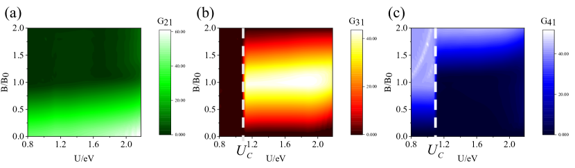
Consider a nonzero bias is applied to electrode I, and the nonlocal conductances between electrode I and the other three as a function of the surface potential and magnetic field are plotted in Fig. 4. The unit of the magnetic field is set to the critical value with the span of the FA in the direction [Fig. 3(d)] and the separation between electrodes I and II [Fig. 3(c)]. is the critical field strength to drive all incident electrons to the Weyl node and penetrate into the bulk before they reach electrode II. As discussed previously, a surface gate potential can induce the Lifshitz transition in the FAs on the top surface. We denote the gate voltage corresponding to the transition point by . Rich information is involved in the conductance patterns in Fig. 4, which can be interpreted by looking at the -dependence of the conductances before and after the Lifshitz transition.
For , since the FAs on the top and bottom surfaces form two independent Weyl orbits, the right-moving electrons from electrode I can only slide along the right loop in Fig. 3(b). Moreover, the states of the FAs on the top and bottom surfaces possess opposite group velocities. As a result, electrons have two kinds of trajectories, propagating from electrode I to II directly or, transmitting into the bottom surface and being reflected back into electrode IV [cf. Figs. 3(a)]. As increases from zero, more incident electrons takes the latter trajectory [yellow arrowed lines in Fig. 3(a)]. As a result, increases while decreases for a larger as shown in Figs. 4(a,c). Meanwhile, no electron can reach electrode III and so the nonlocal conductance vanishes in this regime; see Fig. 4(b).
For , the Lifshitz transition occurs which gives rise to a drastic modification of the trajectories of electrons and accordingly, different -dependence of the conductances. First, always decreases for a stronger magnetic field, which is similar to the situation for . The main difference is the -dependence of and . Due to the unique trajectory sketched by the green arrowed lines in Fig. 3(c), is switched on by the Lifshitz transition and increases with for ; see Fig. 4(b). Accordingly, is switched off in this region [Fig. 4(c)] because the yellow trajectory in Fig. 3(a) is absent. Instead, the electrons need to take more complex trajectory sketched by the purple arrowed lines in Fig. 3(c) to reach electrode IV, which needs a stronger magnetic field. Such abrupt changes of and with manifest the topological Lifshitz transition of the FAs and the Weyl orbits. As reach the critical value , all electrons penetrate to the bottom surface and lead to a maximum ; see Fig. 4(b). As increases further, the purple trajectory in Fig. 3(c) comes into play, which results in an increase of accompanied by a decrease of ; see Figs. 4(c) and 4(b).
IV Discussions
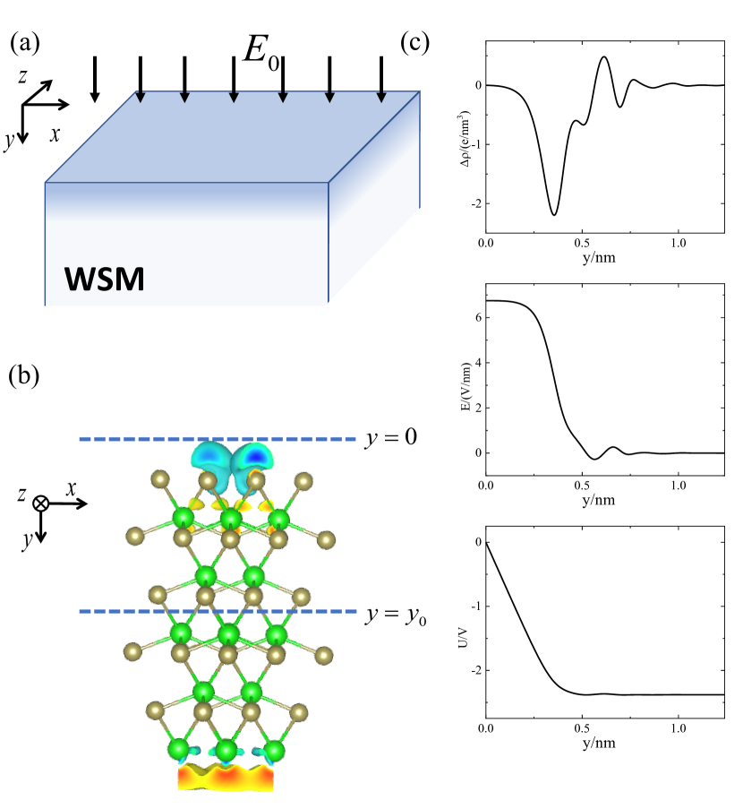
We discuss the experimental implementation of our proposal. In the previous discussion, all results are obtained based on the minimal model (1) of the WSM and the effect of the surface gate is introduced phenomenologically by the potential . From Fig. 1, one can see that the Lifshitz transition of FAs can be driven by a surface potential with eV. In the following, we show that such a surface potential can be achieved in real WSMs. In reality, the establishment of the surface potential by the gate voltage is sketched in Fig. 5(a). A surface gate creates a vertical electric field, which drives free charges to the sample boundary, where these charges rearrange and achieve equilibrium again due to the screening effect. As a result, a finite ingredient of the charge density and thus that of the electric potential are induced by the surface gate, which leads to a potential difference between the surface and bulk electrons. This is the physical origin of the parameter in the previous calculation.
We show that the strength of the surface potential eV required by the Lifshitz transition of the FAs can be realized in real WSMs. We here take a typical WSM, ZrTe Weng et al. (2016) as an example, and perform first-principles calculations on the charge density difference induced by an external electric field using VASP software package Kresse and Furthmüller (1996a, b). The calculation is performed on a three-layer ZrTe slab with a nm vacuum, and an external electric field is applied perpendicular to the open surface, which is created by a surface gate in the experiment. The sampling of the Brillouin zone in the self-consistent process is taken as the grid of , and the exchange-correlation potential is treated within the generalized gradient approximation Kohn and Sham (1965) of the Perdew-Burke-Ernzerhof type Perdew et al. (1996). The difference of the charge density distribution between V/nm and is plotted in Fig. 5(b). As is shown, negative and positive charge density difference is accumulated on the top and bottom boundaries, respectively. The fluctuation of the charge density on the atomic scale in the - plane is not important so that we take its average value in this plane for simplicity and focus on its distribution in the direction. The charge distribution induced by the external electric field is plotted in Fig. 5(c).Using and and taking into account the vanishing field inside the bulk, , the distribution of and in the direction can be obtained; see Fig. 5(c). One can see that for an external electric field V/nm, a considerable surface potential eV can be induced within the range of 0.3 nm near the surface. Such a result proves that a surface potential sufficient to drive the Lifshitz transition of FAs can be induced by the surface gate voltage, showing the feasibility of our proposal.
The minimal WSM model in Eq. (1) contains a single pair of the FAs on each surface, which has been reported in NbIrTe4 (TaIrTe4) Koepernik et al. (2016); Belopolski et al. (2017); Haubold et al. (2017); Ekahana et al. (2020), WP2 Yao et al. (2019), MoTe2 Wang et al. (2016b), and YbMnBi2 Borisenko et al. (2019). In other WSMs however, more than one pair of FAs exist. We argue that our main conclusion of the gate tunable Lifshitz transition of the FAs should maintain in all these realistic cases. First, the feature of the surface bands that can sustain FAs generally allow the existence of the saddle points, which is the key scenario of the Lifshitz transition; Second, the surface bands can be generally tuned by the surface gate voltage, which is the other ingredient of our scheme. Moreover, for the surface bands in realistic materials, some saddle points may lie naturally near the Fermi energy so that the surface potential required by the Lifshitz transition may be much smaller than eV in our model, which further facilitates its implementation. As for the detecting proposal, the stripe electrodes can be fabricated on the WSM by state-of-the-art techniques Li et al. (2020); Chen et al. (2018b); Ghatak et al. (2018). FAs with regular shapes are profitable to our proposal, as the spatial trajectories of electrons possess regular configurations accordingly. Moreover, a big separation between Weyl points in the momentum space Sun et al. (2015); Koepernik et al. (2016); Chang et al. (2016); Yao et al. (2019); Borisenko et al. (2019); Sie et al. (2019) is also beneficial for our proposal, in which visible transport signatures can be expected.
V Summary
To conclude, we show that topological Lifshitz transition of FAs can be induced by a surface gate voltage. Such a transition is attributed to the existence of saddle points in the surface bands, which meets the Fermi energy at the critical transition point. A direct result due to the Lifshitz transition is the abrupt change of the magnetic Weyl orbits composed of both the FAs and bulk Landau bands. Such an effect can be detected by nonlocal transport signatures and the Lifshitz transition can be visibly revealed by the switch on and off of the nonlocal conductances.
Acknowledgements.
This work was supported by the National Natural Science Foundation of China under Grant No. 12074172 (W.C.), No. 12222406 (W.C.) and No. 12174182 (D.Y.X.), the State Key Program for Basic Researches of China under Grants No. 2021YFA1400403 (D.Y.X.), the Fundamental Research Funds for the Central Universities (W.C.), the startup grant at Nanjing University (W.C.) and the Excellent Programme at Nanjing University.References
- Qi and Zhang (2011) X.-L. Qi and S.-C. Zhang, Rev. Mod. Phys. 83, 1057 (2011).
- Hasan and Kane (2010) M. Z. Hasan and C. L. Kane, Rev. Mod. Phys. 82, 3045 (2010).
- Kane and Mele (2005) C. L. Kane and E. J. Mele, Phys. Rev. Lett. 95, 226801 (2005).
- Armitage et al. (2018) N. Armitage, E. Mele, and A. Vishwanath, Reviews of Modern Physics 90, 015001 (2018).
- Hasan et al. (2017) M. Z. Hasan, S.-Y. Xu, I. Belopolski, and S.-M. Huang, Annual Review of Condensed Matter Physics 8, 289 (2017).
- Wan et al. (2011) X. Wan, A. M. Turner, A. Vishwanath, and S. Y. Savrasov, Physical Review B 83, 205101 (2011).
- Zhang et al. (2017) X. Zhang, L. Jin, X. Dai, and G. Liu, The journal of physical chemistry letters 8, 4814 (2017).
- Yu et al. (2017) R. Yu, Z. Fang, X. Dai, and H. Weng, Frontiers of Physics 12, 1 (2017).
- Li et al. (2020) C.-Z. Li, A.-Q. Wang, C. Li, W.-Z. Zheng, A. Brinkman, D.-P. Yu, and Z.-M. Liao, Nature communications 11, 1 (2020).
- Burkov et al. (2011) A. A. Burkov, M. D. Hook, and L. Balents, Phys. Rev. B 84, 235126 (2011).
- Xu et al. (2015a) S.-Y. Xu, I. Belopolski, N. Alidoust, M. Neupane, G. Bian, C. Zhang, R. Sankar, G. Chang, Z. Yuan, C.-C. Lee, et al., Science 349, 613 (2015a).
- Xu et al. (2015b) S.-Y. Xu, N. Alidoust, I. Belopolski, Z. Yuan, G. Bian, T.-R. Chang, H. Zheng, V. N. Strocov, D. S. Sanchez, G. Chang, et al., Nature Physics 11, 748 (2015b).
- Xu et al. (2015c) S.-Y. Xu, I. Belopolski, D. S. Sanchez, C. Zhang, G. Chang, C. Guo, G. Bian, Z. Yuan, H. Lu, T.-R. Chang, et al., Science advances 1, e1501092 (2015c).
- Xu et al. (2016) N. Xu, H. Weng, B. Lv, C. E. Matt, J. Park, F. Bisti, V. N. Strocov, D. Gawryluk, E. Pomjakushina, K. Conder, et al., Nature communications 7, 11006 (2016).
- Huang et al. (2016) L. Huang, T. M. McCormick, M. Ochi, Z. Zhao, M.-T. Suzuki, R. Arita, Y. Wu, D. Mou, H. Cao, J. Yan, et al., Nature materials 15, 1155 (2016).
- Tamai et al. (2016) A. Tamai, Q. Wu, I. Cucchi, F. Y. Bruno, S. Riccò, T. Kim, M. Hoesch, C. Barreteau, E. Giannini, C. Besnard, et al., Physical Review X 6, 031021 (2016).
- Deng et al. (2016) K. Deng, G. Wan, P. Deng, K. Zhang, S. Ding, E. Wang, M. Yan, H. Huang, H. Zhang, Z. Xu, et al., Nature Physics 12, 1105 (2016).
- Yang et al. (2015) L. Yang, Z. Liu, Y. Sun, H. Peng, H. Yang, T. Zhang, B. Zhou, Y. Zhang, Y. Guo, M. Rahn, et al., Nature physics 11, 728 (2015).
- Jiang et al. (2017) J. Jiang, Z. Liu, Y. Sun, H. Yang, C. Rajamathi, Y. Qi, L. Yang, C. Chen, H. Peng, C. Hwang, et al., Nature communications 8, 13973 (2017).
- Belopolski et al. (2016) I. Belopolski, D. S. Sanchez, Y. Ishida, X. Pan, P. Yu, S.-Y. Xu, G. Chang, T.-R. Chang, H. Zheng, N. Alidoust, et al., Nature communications 7, 13643 (2016).
- Lv et al. (2015a) B. Lv, N. Xu, H. Weng, J. Ma, P. Richard, X. Huang, L. Zhao, G. Chen, C. Matt, F. Bisti, et al., Nature Physics 11, 724 (2015a).
- Murakami (2007) S. Murakami, New Journal of Physics 9, 356 (2007).
- Huang et al. (2015a) S.-M. Huang, S.-Y. Xu, I. Belopolski, C.-C. Lee, G. Chang, B. Wang, N. Alidoust, G. Bian, M. Neupane, C. Zhang, et al., Nature communications 6, 7373 (2015a).
- Lv et al. (2015b) B. Lv, H. Weng, B. Fu, X. Wang, H. Miao, J. Ma, P. Richard, X. Huang, L. Zhao, G. Chen, et al., Physical Review X 5, 031013 (2015b).
- Adler (1969) S. L. Adler, Phys. Rev. 177, 2426 (1969).
- Bell and Jackiw (1969) J. S. Bell and R. Jackiw, Il Nuovo Cimento A (1965-1970) 60, 47 (1969).
- Zyuzin and Burkov (2012) A. A. Zyuzin and A. A. Burkov, Phys. Rev. B 86, 115133 (2012).
- Zhou et al. (2013) J.-H. Zhou, H. Jiang, Q. Niu, and J.-R. Shi, Chinese Physics Letters 30, 027101 (2013).
- Burkov (2015) A. Burkov, Journal of Physics: Condensed Matter 27, 113201 (2015).
- Aji (2012) V. Aji, Phys. Rev. B 85, 241101 (2012).
- Son and Spivak (2013) D. T. Son and B. Z. Spivak, Phys. Rev. B 88, 104412 (2013).
- Chernodub et al. (2014) M. N. Chernodub, A. Cortijo, A. G. Grushin, K. Landsteiner, and M. A. H. Vozmediano, Phys. Rev. B 89, 081407 (2014).
- Ma and Pesin (2015) J. Ma and D. A. Pesin, Phys. Rev. B 92, 235205 (2015).
- Zhong et al. (2016) S. Zhong, J. E. Moore, and I. Souza, Phys. Rev. Lett. 116, 077201 (2016).
- Spivak and Andreev (2016) B. Z. Spivak and A. V. Andreev, Phys. Rev. B 93, 085107 (2016).
- Hirschberger et al. (2016) M. Hirschberger, S. Kushwaha, Z. Wang, Q. Gibson, S. Liang, C. A. Belvin, B. A. Bernevig, R. J. Cava, and N. P. Ong, Nature materials 15, 1161 (2016).
- Wang et al. (2016a) Z. Wang, Y. Zheng, Z. Shen, Y. Lu, H. Fang, F. Sheng, Y. Zhou, X. Yang, Y. Li, C. Feng, and Z.-A. Xu, Phys. Rev. B 93, 121112 (2016a).
- Nielsen and Ninomiya (1981) H. B. Nielsen and M. Ninomiya, Nuclear Physics B 185, 20 (1981).
- Nielsen and Ninomiya (1983) H. B. Nielsen and M. Ninomiya, Physics Letters B 130, 389 (1983).
- Wang et al. (2017) S. Wang, B.-C. Lin, A.-Q. Wang, D.-P. Yu, and Z.-M. Liao, Advances in Physics: X 2, 518 (2017).
- Lu and Shen (2017) H.-Z. Lu and S.-Q. Shen, Frontiers of Physics 12, 1 (2017).
- Zheng and Zahid Hasan (2018) H. Zheng and M. Zahid Hasan, Advances in Physics: X 3, 1466661 (2018).
- Huang et al. (2015b) X. Huang, L. Zhao, Y. Long, P. Wang, D. Chen, Z. Yang, H. Liang, M. Xue, H. Weng, Z. Fang, X. Dai, and G. Chen, Phys. Rev. X 5, 031023 (2015b).
- Shekhar et al. (2015) C. Shekhar, A. K. Nayak, Y. Sun, M. Schmidt, M. Nicklas, I. Leermakers, U. Zeitler, Y. Skourski, J. Wosnitza, Z. Liu, et al., Nature Physics 11, 645 (2015).
- Du et al. (2016) J. Du, H. Wang, Q. Chen, Q. Mao, R. Khan, B. Xu, Y. Zhou, Y. Zhang, J. Yang, B. Chen, et al., Science China Physics, Mechanics & Astronomy 59, 657406 (2016).
- Zhang et al. (2016) C.-L. Zhang, S.-Y. Xu, I. Belopolski, Z. Yuan, Z. Lin, B. Tong, G. Bian, N. Alidoust, C.-C. Lee, S.-M. Huang, et al., Nature communications 7, 1 (2016).
- Morali et al. (2019) N. Morali, R. Batabyal, P. K. Nag, E. Liu, Q. Xu, Y. Sun, B. Yan, C. Felser, N. Avraham, and H. Beidenkopf, arXiv preprint arXiv:1903.00509 (2019).
- Yang et al. (2019) H. Yang, L. Yang, Z. Liu, Y. Sun, C. Chen, H. Peng, M. Schmidt, D. Prabhakaran, B. Bernevig, C. Felser, et al., Nature communications 10, 1 (2019).
- Ekahana et al. (2020) S. A. Ekahana, Y. W. Li, Y. Sun, H. Namiki, H. F. Yang, J. Jiang, L. X. Yang, W. J. Shi, C. F. Zhang, D. Pei, C. Chen, T. Sasagawa, C. Felser, B. H. Yan, Z. K. Liu, and Y. L. Chen, Phys. Rev. B 102, 085126 (2020).
- Lifshitz et al. (1960) I. Lifshitz et al., Sov. Phys. JETP 11, 1130 (1960).
- Chen et al. (2018a) W. Chen, K. Luo, L. Li, and O. Zilberberg, Physical review letters 121, 166802 (2018a).
- Chen et al. (2020) G. Chen, O. Zilberberg, and W. Chen, Phys. Rev. B 101, 125407 (2020).
- Zheng et al. (2021) Y. Zheng, W. Chen, and D. Y. Xing, Phys. Rev. B 104, 075420 (2021).
- Chen et al. (2021) X.-R. Chen, G. Chen, Y. Zheng, W. Chen, and D. Y. Xing, Phys. Rev. B 104, 205412 (2021).
- Fleck et al. (1997) M. Fleck, A. M. Oleś, and L. Hedin, Physical Review B 56, 3159 (1997).
- Rice and Scott (1975) T. Rice and G. Scott, Physical Review Letters 35, 120 (1975).
- Gonzalez (2008) J. Gonzalez, Physical Review B 78, 205431 (2008).
- Potter et al. (2014) A. C. Potter, I. Kimchi, and A. Vishwanath, Nature communications 5, 1 (2014).
- Groth et al. (2014) C. W. Groth, M. Wimmer, A. R. Akhmerov, and X. Waintal, New Journal of Physics 16, 063065 (2014).
- Weng et al. (2016) H. Weng, C. Fang, Z. Fang, and X. Dai, Physical Review B 94, 165201 (2016).
- Kresse and Furthmüller (1996a) G. Kresse and J. Furthmüller, Computational materials science 6, 15 (1996a).
- Kresse and Furthmüller (1996b) G. Kresse and J. Furthmüller, Physical review B 54, 11169 (1996b).
- Kohn and Sham (1965) W. Kohn and L. J. Sham, Physical review 140, A1133 (1965).
- Perdew et al. (1996) J. P. Perdew, K. Burke, and M. Ernzerhof, Physical review letters 77, 3865 (1996).
- Koepernik et al. (2016) K. Koepernik, D. Kasinathan, D. V. Efremov, S. Khim, S. Borisenko, B. Büchner, and J. van den Brink, Phys. Rev. B 93, 201101 (2016).
- Belopolski et al. (2017) I. Belopolski, P. Yu, D. S. Sanchez, Y. Ishida, T.-R. Chang, S. S. Zhang, S.-Y. Xu, H. Zheng, G. Chang, G. Bian, et al., Nature communications 8, 1 (2017).
- Haubold et al. (2017) E. Haubold, K. Koepernik, D. Efremov, S. Khim, A. Fedorov, Y. Kushnirenko, J. van den Brink, S. Wurmehl, B. Büchner, T. K. Kim, M. Hoesch, K. Sumida, K. Taguchi, T. Yoshikawa, A. Kimura, T. Okuda, and S. V. Borisenko, Phys. Rev. B 95, 241108 (2017).
- Yao et al. (2019) M.-Y. Yao, N. Xu, Q. S. Wu, G. Autès, N. Kumar, V. N. Strocov, N. C. Plumb, M. Radovic, O. V. Yazyev, C. Felser, J. Mesot, and M. Shi, Phys. Rev. Lett. 122, 176402 (2019).
- Wang et al. (2016b) Z. Wang, D. Gresch, A. A. Soluyanov, W. Xie, S. Kushwaha, X. Dai, M. Troyer, R. J. Cava, and B. A. Bernevig, Phys. Rev. Lett. 117, 056805 (2016b).
- Borisenko et al. (2019) S. Borisenko, D. Evtushinsky, Q. Gibson, A. Yaresko, K. Koepernik, T. Kim, M. Ali, J. van den Brink, M. Hoesch, A. Fedorov, et al., Nature communications 10, 1 (2019).
- Chen et al. (2018b) A. Q. Chen, M. J. Park, S. T. Gill, Y. Xiao, D. Reig-i Plessis, G. J. MacDougall, M. J. Gilbert, and N. Mason, Nature communications 9, 1 (2018b).
- Ghatak et al. (2018) S. Ghatak, O. Breunig, F. Yang, Z. Wang, A. A. Taskin, and Y. Ando, Nano letters 18, 5124 (2018).
- Sun et al. (2015) Y. Sun, S.-C. Wu, M. N. Ali, C. Felser, and B. Yan, Phys. Rev. B 92, 161107 (2015).
- Chang et al. (2016) G. Chang, S.-Y. Xu, D. S. Sanchez, S.-M. Huang, C.-C. Lee, T.-R. Chang, G. Bian, H. Zheng, I. Belopolski, N. Alidoust, H.-T. Jeng, A. Bansil, H. Lin, and M. Z. Hasan, Science Advances 2 (2016), 10.1126/sciadv.1600295, https://advances.sciencemag.org/content/2/6/e1600295.full.pdf .
- Sie et al. (2019) E. J. Sie, C. M. Nyby, C. Pemmaraju, S. J. Park, X. Shen, J. Yang, M. C. Hoffmann, B. Ofori-Okai, R. Li, A. H. Reid, et al., Nature 565, 61 (2019).