Quantum Mechanical Assessment of Optimal Photovoltaic Conditions in Organic Solar Cells
Abstract
Recombination losses contribute to reduce , and the fill factor of organic solar cells. Recent advances in non-fullerene organic photovoltaics have shown, nonetheless, that efficient charge generation can occur under small energetic driving forces () and low recombination losses. To shed light on this issue, we set up a coarse-grained open quantum mechanical model for investigating the charge generation dynamics subject to various energy loss mechanisms. The influence of energetic driving force, Coulomb interaction, vibrational disorder, geminate recombination, temperature and external bias are included in the analysis of the optimal photovoltaic conditions for charge carrier generation. The assessment reveals that the overall energy losses are not only minimized when approaches the effective reorganization energy at the interface but also become insensitive to temperature and electric field variations. It is also observed that a moderate reverse bias reduces geminate recombination losses significantly at vanishing driving forces, where the charge generation is strongly affected by temperature.
![[Uncaptioned image]](/html/2210.12537/assets/TOC.png)
Efficient charge generation has always been a major concern for organic photovoltaics (OPV) due to the strong exciton binding energy in organic materials.Clarke and Durrant (2010); Armin et al. (2021); Cheng et al. (2018); Hallermann et al. (2008); Menke and Holmes (2014) Thus, fullerene derivatives have been used as prototypical electron acceptor materials, because of their remarkable electron-accepting capabilities. However, the efficiency of fullerene-based organic solar cells (OCS) has stagnated around 13% as a consequence of the excessive energy losses undergone to achieve electron-hole (e-h) charge separation, and the very poor optical characteristics of the C60 molecule that does not contribute to charge generation. Meanwhile, a new class of non-fullerene acceptor (NFA) materials have been developed, which revealed a new paradigm for OPV, one of efficient charge generation and high output voltage despite lower energetic gradients at the heterojunction. Nowadays, the conversion efficiency of the NFA devices is approaching the barrier of 20%,Armin et al. (2021) as a result of the high photo-absorption of non-fullerene small molecules; the push-pull design of the NFA molecules that facilitate the electron-hole pair separation upon photoexcitation; the complementary light-harvesting roles played by large band-gap donor materials and low-bandgap NFA materials; besides the beneficial morphological properties of the NFA molecules (e.g., miscibility, stability, and planarity). For OSCs the output voltage is given by ,Rosenthal et al. (2019); Liu et al. (2016); Hou et al. (2018) where is related to the energetic driving forceLiu et al. (2016); Perdigón-Toro et al. (2020) and the voltage losses due to recombination comprise both radiative () and non-radiative () pathways. In NFA-OSCs the voltage loss mechanisms have been empirically reduced whereas the interplay among the relevant physical processes at the D:A interface remains a subject of study.Rosenthal et al. (2019); Liu et al. (2016); Perdigón-Toro et al. (2020); Coropceanu et al. (2019); Gao et al. (2015); Eisner et al. (2019); Classen et al. (2020); Chen et al. (2021); Chan et al. (2021); Benduhn et al. (2017); Qian et al. (2018); Hofinger et al. (2021); Chen et al. (2018)
In this paper we combine the Ehrenfest and Redfield methods in a coarse-grained open quantum mechanical model to investigate, from a fundamental point of view, the energy loss effects that occur during the free charge carrier generation process at the D:A interface. We study the influence of the energetic driving, temperature and external bias on the charge generation process. The simulation results demonstrate that the overall energy losses are minimized at the activationless regime of the charge separation, where driving force matches the effective reorganization energy of the heterojunction, corroborating experimental studies.Coffey et al. (2012); Ward et al. (2015); Rand et al. (2007) Moreover, the optimal photovoltaic condition is insensitive to variations of temperature and reverse bias.
We partition the total Hamiltonian, responsible for the charge generation and recombination processes, as
| (1) |
The system Hamiltonian, , comprises the degrees of freedom of the electron and the hole and a subset of vibrational reorganization modes that are described as classical modes within the framework of the Ehrenfest self-consistent method. Thus, is a mixed quantum-classical Hamiltonian (details provided in Support Information). The bath Hamiltonian, , accounts for the degrees of freedom of the environment, namely the vibrational degrees of freedom and fluctuations of the dielectric background, which we describe as an ensemble of quantum harmonic oscillators. The system-bath coupling () is described within the framework of the Redfield theory. Using the adiabatic representation for the system Hamiltonian, , the Redfield equation for the reduced density matrix reads
| (2) |
where designates the eigenfrequencies of the electronic system and is the Redfield relaxation tensor.Redfield (1957, 1965) The first term on the right-hand-side (RHS) of Eq. (2) describes the coherent quantum dynamics of S, the second term describes the interaction of S with the environment. The implementation of the Redfield equations for this model has been described elsewhere.Andermann and Rego (2022) Later on we will incorporate a term for the recombination effects into Eq. (2).
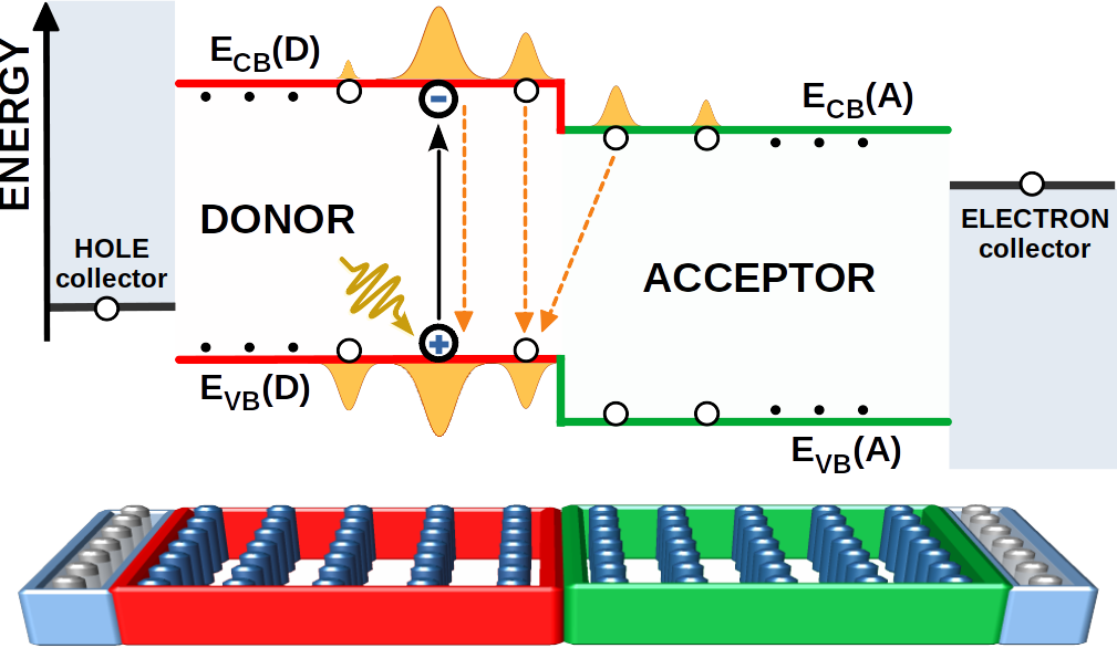
The D:A interface is modelled as a two-dimensional (2D) coarse-grained lattice, with energy profile corresponding to a staggered (type II) interface, as described in Figure 1. The spatial arrangement of the 2D-D:A interface is shown at the bottom of the figure, where each site of the lattice represents a molecular site in the coarse-grained model. Periodic boundary conditions are applied along the transverse direction. In the simulations, we consider the photoexcitation of a molecular site of the donor material, but the obtained results are equally valid for a photoexcitation in the acceptor material. After charge separation, the electron and hole are collected at the respective collecting layers at the border of the 2D lattice (see Figure 1). The electron and hole collecting layers in the model do not represent the actual cathode and anode terminals of the device, they are simply used as a theoretical tool to avoid the reflection of the wavepackets at the left and right boundaries; they are positioned below and above , respectively.
The coarse-grained Hamiltonian , for either the electron and hole photoexcited particles, is
| (3) |
where denotes the total number of molecular sites in the lattice. The orthogonal basis set { consists of diabatic states associated with each of the molecular sites. In addition, and are the on-site energies of the electron (conduction band) and hole (valence band); is the confinement energy associated with site ; and describes the electron-hole electrostatic interaction, given in the time-dependent mean-field approximation by
| (4) |
where is the on-site electron-hole binding energy (refer to Table 1 for a complete list of model parameters), () is the time-dependent electron (hole) population on site and is the distance between molecular sites and . The treatment accounts for the decrease of the el-hl Coulomb barrier induced by the charge delocalization, besides describing the influence of temperature in the el-hl separation, as shown elsewhere.Andermann and Rego (2022) The last term in Eq. (S3),
| (5) |
describes the tunneling energy between lattice sites, where is the bare electronic coupling and the form factor is the time-dependent overlap between lattice sites and , with being the confinement radius of the molecular site (see SI for details). The time dependence of the energy parameters comprising Eq (S3), namely and gives rise to the intra-molecular and inter-molecular vibrational effects, respectively, that we associate with the Holstein and Peierls couplings.Andermann and Rego (2022) The treatment includes dynamic disorder, which is taken into account by the intra-molecular and inter-molecular electron-phonon couplings in the system Hamiltonian (). The dynamic disorder is also taken into account in the system-bath Hamiltonian () that gives rise to the Redfield relaxation tensor and, lastly, through the action of the classical Berendsen thermostat that acts on the molecular sites (describe in SI). These interactions give rise to localization of the electron and hole wavepackets,Candiotto et al. (2017) polaron formation,Andermann and Rego (2022) and temperature dependence of the charge generation rate. The model does not include static disorder.
Recombination is the main efficiency loss mechanism in photovoltaics, even more so in OSCs due to the convoluted charge separation process in organic devices. Recombination processes can be separated in two types: geminate and non-geminate (including bimolecular and trap-assisted processes). The former designates the annihilation of a correlated electron-hole pair generated by the same photoexcitation event, or the recombination of a charge separated (CT) state before complete dissociation. Experiments have shown that geminate recombination is more important at short-circuit and low illumination conditions.Credgington et al. (2012) Bimolecular recombination, on the other hand, involves fully dissociated carriers generated by independent photoabsorption events. It is more relevant at open-circuit and/or high excitation conditions. A quantum mechanical model that is well suited for describing the geminate recombination in molecular systems is the Haberkorn model. It was initially proposed to describe recombination in radical pairs,Haberkorn (1976) but later was used to describe the trapping and exciton recombination in the Fenna-Matthews-Olson (FMO) protein complexRebentrost et al. (2009) and OSC models.Candiotto et al. (2017) Herein we include the vibrational dynamics, in addition to the electron-hole dynamics to extend the plain Haberkorn formalism. Thus, consider a quantum state that comprises the reduced density matrix , where designates the type of charge carrier. As in the Haberkorn model, the mutual annihilation of electrons and holes is given by the dynamical equation
| (6) |
where is the carrier type opposite to . To include the vibrational effects into the Haberkorn recombination model, we use the operator , defined as
| (7) |
where the symmetric operator includes the molecular site vibrations, as defined in Eq. (S4). The parameter in Eq. (S10) (see Table 1) is a molecular decay rate constant. Coropceanu and collaboratorsCoropceanu et al. (2019); Chen et al. (2021) associate with the Einstein spontaneous emission rate for the radiative recombination term whereas the Marcus-Levich-Jortner (MLJ) formula was used to define the non-radiative decay rate ; herein we use the same parameter for both processes. A comparison between the vibronic Haberkorn model and the three-state modelCoropceanu et al. (2019); Benduhn et al. (2017); Qian et al. (2018); Eisner et al. (2019); Chen et al. (2021) is presented as SI. Substitution of Eq. (S10) into Eq. (6) yields the following equation for the coefficients of the wavepacket in the molecular site basis
| (8) |
Rewriting Eq. (8) in terms of the time derivative of the reduced density matrix, , we get
| (9) |
The quantum mechanical recombination rate given by Eq. (9), for geminate recombination, can be associated with the classical law of mass action for the rate of bimolecular recombination , where and are the concentrations of free electrons and holes, respectively, and is an effective recombination constant given, for instance, by the Langevin model.Burke et al. (2015) It is also worth noting that Eq. (9) gives the recombination losses during the exciton diffusion and for the CT state at the D:A interface.
Before adding this recombination rate term to the Redfield Master Equation, Eq. (2), it is transformed to the adiabatic representation of basis states by , where is the unitary operator that diagonalizes . The overall charge neutrality of the heterojunction is conserved with Eq. (9). Based on Eq. (9), the energy lost by a molecular site via recombination is calculated as where is the population lost by recombination and is the corresponding CB-VB gap. The total energy loss due to recombination is calculated as , where the sum runs over all the molecular sites and is the final simulation time. Therefore, to obtain the voltage loss due to geminate recombination () during the charge separation process we calculate
| (10) |
where is the electronic charge. Notice that this method accounts only for the geminate electron-hole recombination. Bimolecular recombination processes become important at open circuit conditions and high excitation intensities, which are not described by the present simulations.
The model parameters used in the simulations are presented in Table 1. The set of coupled differential equations produced by combining Eqs. (2) and (9) are solved numerically by a fourth order adaptive step size Runge-Kutta method. We simulate the process of free charge generation, including exciton photoexcitation, excition diffusion, CT state formation and separation, for a single el-hl pair in the presence of geminate recombination, during a time frame of ten picoseconds.
| value | description | |
|---|---|---|
| 84 | number of sites | |
| 0.5 nm | confinement radius for the empty molecular site | |
| meV | nearest-neighbor electronic coupling | |
| 1.3 nm | distance of nearest neighbor sites | |
| 0.2 eV | electron-hole coupling constant | |
| 50 meV | reorganization energy | |
| 1334 (165 meV) | cutoff frequency | |
| 272 (34 meV) | classical normal mode frequency | |
| ps | phonon-phonon relaxation time | |
| 1 ps-1 | molecular site decay rate constant |
We consider that a Frenkel exciton is photoexcited in the center of the donor region, as shown in Figure 1. The coarse-grained model consists of a 2D-square lattice with nearest neighbor (nn) distance = 1.3 nm and equal D and A domain lengths of approximately 7.5 nm. The effective electronic coupling between nearest neighbors is set to be meV, as given by Eq. (S4), which is in agreement with other molecular crystal models.Lee et al. (2015); Coropceanu et al. (2007); Mozafari and Stafström (2013); Kocherzhenko et al. (2015); De Sio and Lienau (2017); Troisi and Orlandi (2006); Candiotto et al. (2017) The low frequency vibration mode is treated classically. It modulates the radii of the molecular sites and, thereby, the electronic coupling , as given by (S4). The classical vibrations are self-consistently coupled to the el-hl quantum states by semiclassical Ehrenfest forces (Supporting Information). The high energy quantum vibrations are incorporated into the Redfield relaxation tensor, up to the cutoff frequency = 1334 cm-1 that corresponds to the localized CC stretching mode. For the system-bath coupling we use a reorganization energy parameter of = 50 meV for either the electron and hole density matrices. The magnitude of is commonly found to be in the range of 100-300 meV for organic blends.Vandewal et al. (2017) However, it has been shown that the values of obtained from experiments tend to be larger than the bare values obtained by static calculations. Vanderwal et al.Vandewal et al. (2017) derived the empirical relationship , where 95 meV is a correction due to dynamic disorder (disregarding the static disorder). Additionally, McGehee et al.Burke et al. (2015) derived another relation in which , where is the static energetic disorder parameter and 108 meV at room temperature, assuming = 75 meV. can be associated with the CT emission spectral broadening that is caused by disorder. In our model we ascribe the effects of disorder fully to the molecular vibrations. Therefore, the effective reorganization energy affecting the el-hl dynamics in our simulations can be estimated as . This is in good agreement with the optimal charge generation conditions obtained in our simulations, which is given that occurs between 100 and 200 meV, as shown ahead. As for the recombination rate constant, , its value is defined based on the characteristics of the coarse-grained model. Experiments have determined that the exciton diffusion length in organic semiconductors and polymers is within the range of 5-20 nm,Mikhnenko et al. (2012); Firdaus et al. (2020) and the diffusion length is limited by the exciton lifetime. In our coarse-grained model the length of the donor (D) domain is about 7.5 nm, which should correspond approximately to an exciton lifetime. To follow this constraint and to evince the effects of the recombination within the span of the simulation time (10 ps), we use = 1 ps-1. For the sake of comparison, Figure S4 in the Supporting Information presents simulation results with and without recombination. Finally, in accordance with the model (Figure 1), we define the energetic driving force of the D:A interface as .
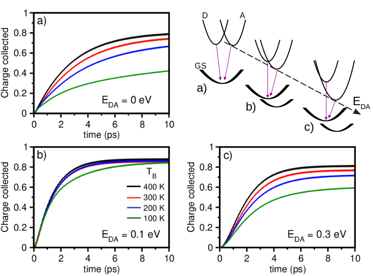
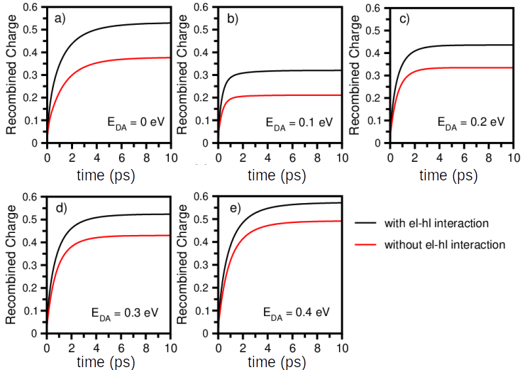
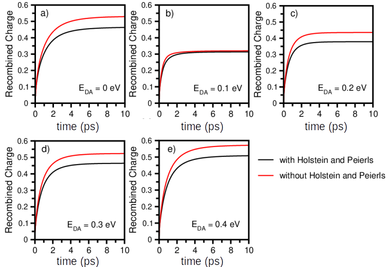
The evaluation of the activation energy (Ea) required for el-hl pair separation has been open to debate,Gao et al. (2015); Dong et al. (2019); Perdigón-Toro et al. (2020); Rosenthal et al. (2019); Coffey et al. (2012); Ward et al. (2015); Unger et al. (2017) given that the obtained values may vary depending on the technique and the time scale of the measurements. From the theoretical viewpoint, considering the kinetic models, Ea is an effective parameter that is influenced by Coulombic dissociation and recombination rates.Gao et al. (2015); Dong et al. (2019); Perdigón-Toro et al. (2020) Figure 2 shows the collected electronic population after recombination, for various bath temperatures (TB) and energetic driving forces (), that is , without electric field bias. The simulations show, as a whole, that the charge generation rate increases with temperature for all D:A offsets. In addition, the effect of TB on reveals three distinct electron separation regimes, as depicted in the inset of Figure 2: a) the normal electron separation for negligible = 0 eV; b) the activationless regime for 0.1 eV; and c) the inverted Marcus regime for = 0.3 eV. The highest internal quantum efficiency (IQE) is obtained for the activationless regime, 0.1 eV, whereby the charge generation process is almost independent of the temperature. The maximum IQE is obtained for , where corresponds to the effective reorganization energy at the heterojunction, corroborating experimental studies that show the existence of such an optimal driving force.Coffey et al. (2012); Ward et al. (2015); Rand et al. (2007) However, for vanishing energetic driving force, 0, and no electric fields (to be discussed next), the charge generation is very sensitive to the temperature. Lastly, if the energy offset becomes excessive, i.e. , the charge generation process enters the inverted region described by the Marcus-Jortner-Levich theory Jortner (1976); Barbara et al. (1996); Chaudhuri et al. (2017), where charge transfer is assisted by quantum vibronic effects. A detailed account of the impact produced by vibronic effects (such as polaron formation) and internal electric fields on the free charge carrier generation is was presented by Andermann and Rego elsewhere.Andermann and Rego (2022) Figures S2 and S3 of the SI evince the importance of electron-hole interaction and vibrational dynamics to recombination, respectively.
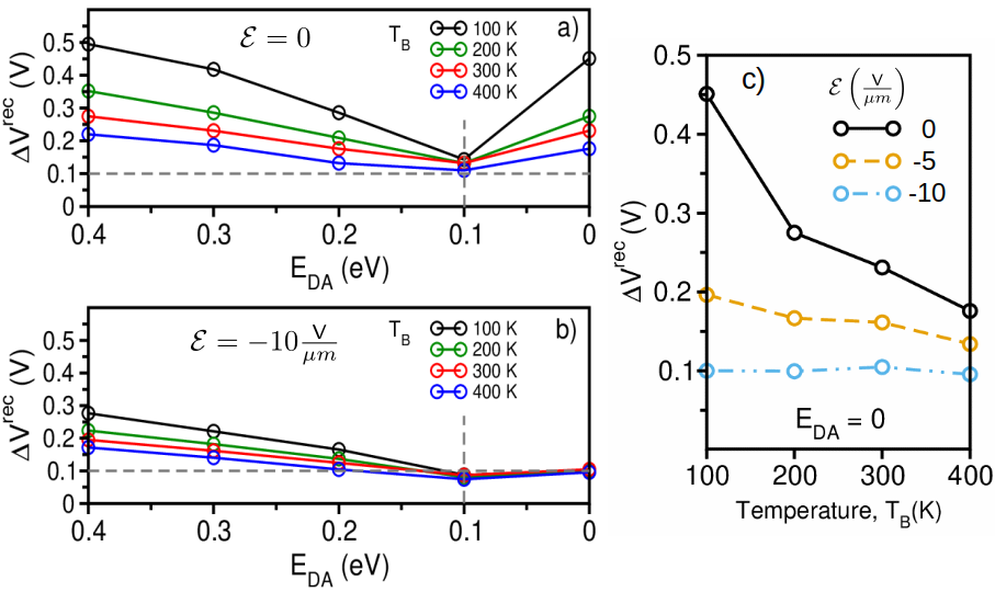
In addition to the energetic driving force for charge separation, the voltage losses in the OSCs also include the contributions from recombination processes, both radiative and non-radiative. Figure 3 shows the effect of driving force (), temperature () and electric field bias () on the voltage loss due to geminate recombination, , as given by Eq. (10). The simulations show that is practically insensitive to temperature and reverse bias field if the energetics of the heterojunction is set to the activationless regime of charge separation, in this case = 0.1 eV. Out of this point the losses due to geminate recombination at the D:A interface increase as the temperature decreases, particularly so for vanishing D:A offset in the absence of reverse bias (Figure 3-a). The influence of temperature on the geminate recombination losses during charge carrier-generation has not been extensively investigated because it is difficult to measure geminate recombination at low illumination intensities, since parasitic leakage currents can affect the results.Proctor and Nguyen (2015) To study this issue, Gao et al.Gao et al. (2015) used low excitation intensities to observe a decreasing VOC at low temperatures, which was ascribed to reduced carrier generation. Here, it is important to distinguish the nonequilibrium carrier generation process that is observed at low illumination intensities from the quasi-equilibrium conditions attained at open-circuit with moderate-to-high illumination. In the first case, the efficiency of charge generation is determined by the competition between photogeneration of free charge carriers and geminate recombination, as described in Figure 3. In the second case, bimolecular recombination kinetics is the main cause of energy loss, so that at the steady-state , where and are the electron and hole stationary free carrier densities.Burke et al. (2015); Gao et al. (2015); Rosenthal et al. (2019) Thus, at high excitation densities and are nearly temperature independent and decreases linearly with temperature.Gao et al. (2015); Rauh et al. (2011) At low excitations, however, the density of free carriers become temperature dependent, and ,Gao et al. (2015); Rauh et al. (2011); Rand et al. (2007); Chan et al. (2021) thereby changing the behavior of . Chan et al.Chan et al. (2021) reported that as the blends P3TEA:SF-PDI2 and PM6:Y6 are cooled, the reduced charge separation rate leads to increasing charge recombination, either directly at the D:A interface or via the LE state. Thus, in this case can exhibit a sublinear dependence on temperature,Vandewal et al. (2010); Rand et al. (2007); Rauh et al. (2011) or even increase with temperatureGao et al. (2015) if the carrier-generation process dominates . Notice, though, that the application of a reverse bias at the heterojunction should promote the free carrier generation,Proctor et al. (2014) thereby decreasing the losses by geminate recombination and improving , as shown in Figure 3-b. The effect of a reverse bias is particularly strong in the absence of driving force (=0), as shown in Figure 3-c, where it is shown that a moderate bias reduces recombination losses substantially.
The various recombination pathways contribute to reduce , and the fill factor (FF) of the OSCs, thereby limiting its power conversion efficiency. In regard to free carrier generation, this work indicates that the best device performances should be realized at the optimal offset , which produces low overall energy losses for free carrier generation and superior and FF.
Acknowledgements. AMA is grateful for the financial support from FAPESC (Fundação de Amparo à Pesquisa do Estado de Santa Catarina). LGCR acknowledges support by Coordenação de Aperfeiçoamento de Pessoal de Nível Superior Brasil (CAPES) - Finance Code 001, by the Brazilian National Counsel of Technological and Scientific Development (CNPq) and the National Institute for Organic Electronics (INEO). The authors acknowledge support by allocation of supercomputer time from Laboratory for Scientific Computing (LNCC/MCTI, Brazil).
References
- Clarke and Durrant (2010) T. M. Clarke and J. R. Durrant, Chem. Rev. 110, 6736 (2010).
- Armin et al. (2021) A. Armin, W. Li, O. J. Sandberg, Z. Xiao, L. Ding, J. Nelson, D. Neher, K. Vandewal, S. Shoaee, T. Wang, H. Ade, T. Heumüller, C. Brabec, and P. Meredith, Adv. Energy Mater. 11, 2003570 (2021).
- Cheng et al. (2018) P. Cheng, G. Li, X. Zhan, and Y. Yang, Nat. Photonics 12, 131 (2018).
- Hallermann et al. (2008) M. Hallermann, S. Haneder, and E. Da Como, Appl. Phys. Lett. 93, 290 (2008).
- Menke and Holmes (2014) S. M. Menke and R. J. Holmes, Energ. & Environ. Sci. 7, 499 (2014).
- Rosenthal et al. (2019) K. D. Rosenthal, M. P. Hughes, B. R. Luginbuhl, N. A. Ran, A. Karki, S.-J. Ko, H. Hu, M. Wang, H. Ade, and T.-Q. Nguyen, Adv. Energy Mater. 9, 1901077 (2019).
- Liu et al. (2016) J. Liu, S. Chen, D. Qian, B. Gautam, G. Yang, J. Zhao, J. Bergqvist, F. Zhang, W. Ma, H. Ade, O. Inganäs, K. Gundogdu, F. Gao, and H. Yan, Nat. Energy 1, 16089 (2016).
- Hou et al. (2018) J. Hou, O. Inganäs, R. H. Friend, and F. Gao, Nat. Mater. 17, 119 (2018).
- Perdigón-Toro et al. (2020) L. Perdigón-Toro, H. Zhang, A. Markina, J. Yuan, S. M. Hosseini, C. M. Wolff, G. Zuo, M. Stolterfoht, Y. Zou, F. Gao, D. Andrienko, S. Shoaee, and D. Neher, Adv. Mater. 32, 1906763 (2020).
- Coropceanu et al. (2019) V. Coropceanu, X.-K. Chen, T. Wang, Z. Zheng, and J.-L. Brédas, Nat. Rev. Mater. 4, 689 (2019).
- Gao et al. (2015) F. Gao, W. Tress, J. Wang, and O. Inganäs, Phys. Rev. Lett. 114, 128701 (2015).
- Eisner et al. (2019) F. D. Eisner, M. Azzouzi, Z. Fei, X. Hou, T. D. Anthopoulos, T. J. S. Dennis, M. Heeney, and J. Nelson, J. Am. Chem. Soc. 141, 6362 (2019).
- Classen et al. (2020) A. Classen, C. L. Chochos, L. Lüer, V. G. Gregoriou, J. Wortmann, A. Osvet, K. Forberich, I. McCulloch, T. Heumüller, and C. J. Brabec, Nat. Energy 5, 711 (2020).
- Chen et al. (2021) X.-K. Chen, D. Qian, Y. Wang, T. Kirchartz, W. Tress, H. Yao, J. Yuan, M. Hülsbeck, M. Zhang, Y. Zou, Y. Sun, Y. Li, J. Hou, O. Inganäs, V. Coropceanu, J.-L. Bredas, and F. Gao, Nat. Energy 6, 799 (2021).
- Chan et al. (2021) C. C. S. Chan, C. Ma, X. Zou, Z. Xing, G. Zhang, H.-L. Yip, R. A. Taylor, Y. He, K. S. Wong, and P. C. Y. Chow, Adv. Funct. Mater. 31, 2107157 (2021).
- Benduhn et al. (2017) J. Benduhn, K. Tvingstedt, F. Piersimoni, S. Ullbrich, Y. Fan, M. Tropiano, K. A. McGarry, O. Zeika, M. K. Riede, C. J. Douglas, S. Barlow, S. R. Marder, D. Neher, D. Spoltore, and K. Vandewal, Nat. Energy 2, 17053 (2017).
- Qian et al. (2018) D. Qian, Z. Zheng, H. Yao, W. Tress, T. R. Hopper, S. Chen, S. Li, J. Liu, S. Chen, J. Zhang, X.-K. Liu, B. Gao, L. Ouyang, Y. Jin, G. Pozina, I. A. Buyanova, W. M. Chen, O. Inganäs, V. Coropceanu, J.-L. Bredas, H. Yan, J. Hou, F. Zhang, A. A. Bakulin, and F. Gao, Nat. Mater. 17, 703 (2018).
- Hofinger et al. (2021) J. Hofinger, C. Putz, F. Mayr, K. Gugujonovic, D. Wielend, and M. C. Scharber, Mater. Adv. 2, 4291 (2021).
- Chen et al. (2018) X.-K. Chen, V. Coropceanu, and J.-L. Brédas, Nat. Commun. 9, 5295 (2018).
- Coffey et al. (2012) D. C. Coffey, B. W. Larson, A. W. Hains, J. B. Whitaker, N. Kopidakis, O. V. Boltalina, S. H. Strauss, and G. Rumbles, J. Phys. Chem. C 116, 8916 (2012).
- Ward et al. (2015) A. J. Ward, A. Ruseckas, M. M. Kareem, B. Ebenhoch, L. A. Serrano, M. Al-Eid, B. Fitzpatrick, V. M. Rotello, G. Cooke, and I. D. W. Samuel, Adv. Mat. 27, 2496 (2015).
- Rand et al. (2007) B. P. Rand, D. P. Burk, and S. R. Forrest, Phys. Rev. B 75, 115327 (2007).
- Redfield (1957) A. G. Redfield, IBM J. Res. Dev. 1, 19 (1957).
- Redfield (1965) A. Redfield, in Advances in Magnetic and Optical Resonance, Vol. 1 (Elsevier, 1965) pp. 1–32.
- Andermann and Rego (2022) A. M. Andermann and L. G. C. Rego, J. Chem. Phys. 156, 024104 (2022).
- Candiotto et al. (2017) G. Candiotto, A. Torres, K. T. Mazon, and L. G. C. Rego, J. Phys. Chem. C 121, 23276 (2017).
- Credgington et al. (2012) D. Credgington, F. C. Jamieson, B. Walker, T.-Q. Nguyen, and J. R. Durrant, Adv. Mater. 24, 2135 (2012).
- Haberkorn (1976) R. Haberkorn, Mol. Phys. 32, 1491 (1976).
- Rebentrost et al. (2009) P. Rebentrost, M. Mohseni, and A. Aspuru-Guzik, The Journal of Physical Chemistry B 113, 9942 (2009), pMID: 19603843.
- Burke et al. (2015) T. M. Burke, S. Sweetnam, K. Vandewal, and M. D. McGehee, Adv. Energy Mater. 5, 1500123 (2015).
- Lee et al. (2015) M. H. Lee, J. Aragó, and A. Troisi, J. Phys. Chem. C 119, 14989 (2015).
- Coropceanu et al. (2007) V. Coropceanu, J. Cornil, D. A. da Silva Filho, Y. Olivier, R. Silbey, and J.-L. Brédas, Chem. Rev. 107, 926 (2007).
- Mozafari and Stafström (2013) E. Mozafari and S. Stafström, J. Chem. Phys. 138, 184104 (2013).
- Kocherzhenko et al. (2015) A. A. Kocherzhenko, D. Lee, M. A. Forsuelo, and K. B. Whaley, J. Phys. Chem. C 119, 7590 (2015).
- De Sio and Lienau (2017) A. De Sio and C. Lienau, Phys. Chem. Chem. Phys. 19, 18813 (2017).
- Troisi and Orlandi (2006) A. Troisi and G. Orlandi, J. Phys. Chem. A 110, 4065 (2006).
- Vandewal et al. (2017) K. Vandewal, J. Benduhn, K. S. Schellhammer, T. Vangerven, J. E. Rückert, F. Piersimoni, R. Scholz, O. Zeika, Y. Fan, S. Barlow, D. Neher, S. R. Marder, J. Manca, D. Spoltore, G. Cuniberti, and F. Ortmann, J. Am. Chem. Soc. 139, 1699 (2017).
- Mikhnenko et al. (2012) O. V. Mikhnenko, H. Azimi, M. Scharber, M. Morana, P. W. M. Blom, and M. A. Loi, Energy Environ. Sci. 5, 6960 (2012).
- Firdaus et al. (2020) Y. Firdaus, V. M. Le Corre, S. Karuthedath, W. Liu, A. Markina, W. Huang, S. Chattopadhyay, M. M. Nahid, M. I. Nugraha, Y. Lin, A. Seitkhan, A. Basu, W. Zhang, I. McCulloch, H. Ade, J. Labram, F. Laquai, D. Andrienko, L. J. A. Koster, and T. D. Anthopoulos, Nat. Commun. 11, 5220 (2020).
- Dong et al. (2019) Y. Dong, H. Cha, J. Zhang, E. Pastor, P. S. Tuladhar, I. McCulloch, J. R. Durrant, and A. A. Bakulin, J. Chem. Phys. 150, 104704 (2019).
- Unger et al. (2017) T. Unger, S. Wedler, F.-J. Kahle, U. Scherf, H. Bässler, and A. Köhler, J. Phys. Chem. C 121, 22739 (2017).
- Jortner (1976) J. Jortner, J. Chem. Phys. 64, 4860 (1976).
- Barbara et al. (1996) P. F. Barbara, T. J. Meyer, and M. A. Ratner, J. Phys. Chem. 100, 13148 (1996).
- Chaudhuri et al. (2017) S. Chaudhuri, S. Hedström, D. D. Méndez-Hernández, H. P. Hendrickson, K. A. Jung, J. Ho, and V. S. Batista, J. Chem. Theory Comput. 13, 6000 (2017).
- Proctor and Nguyen (2015) C. M. Proctor and T.-Q. Nguyen, Appl. Phys. Lett. 106, 083301 (2015).
- Rauh et al. (2011) D. Rauh, A. Wagenpfahl, C. Deibel, and V. Dyakonov, Appl. Phys. Lett. 98, 133301 (2011).
- Vandewal et al. (2010) K. Vandewal, K. Tvingstedt, A. Gadisa, O. Inganäs, and J. V. Manca, Phys. Rev. B 81, 125204 (2010).
- Proctor et al. (2014) C. M. Proctor, S. Albrecht, M. Kuik, D. Neher, and T.-Q. Nguyen, Adv. Energy Mater. 4, 1400230 (2014).
- Egorova et al. (2001) D. Egorova, A. Kühl, and W. Domcke, Chem. Phys. 268, 105 (2001).
- Egorova et al. (2003) D. Egorova, M. Thoss, W. Domcke, and H. Wang, J. Chem. Phys. 119, 2761 (2003).
- Sachtleben et al. (2017) K. Sachtleben, K. T. Mazon, and L. G. C. Rego, Phys. Rev. Lett. 119, 090601 (2017).
- Berendsen et al. (1984) H. J. Berendsen, J. v. Postma, W. F. van Gunsteren, A. DiNola, and J. R. Haak, J. Chem. Phys. 81, 3684 (1984).
- Rego and Bortolini (2019) L. G. C. Rego and G. Bortolini, J. Phys. Chem. C 123, 5692 (2019).
Supporting Information for
Quantum Mechanical Assessment of Optimal Photovoltaic Conditions in Organic Solar Cells
I Semiclassical Electron-Phonon Hamiltonian
The paraboloids depicted in Figure S1-a) describe the local confinement potential felt by the electron and the hole at a given molecular site. We assume that the parabolic confinement potential undergoes a vibrational reorganization whenever charge is transferred in or out of the molecular site. This mechanism gives rise to coherent vibrational effects that we describe within the framework of the Ehrenfest method. The density profile of the electron and hole in the molecular site is given by the gaussian
| (S1) |
with designating the position of the molecular site, and is the confinement radius of the molecular site, given by
| (S2) |
for a gaussian wavepacket of on-site energy .
To write the system Hamiltonian, , we assume an orthogonal basis set comprised of diabatic electronic states associated with the molecular sites, as described in the paper,
| (S3) |
The coupling between lattice sites is given by
| (S4) |
where is the bare electronic coupling and the form factor results from the overlap between gaussian wavepackets located at lattice sites and
| (S5) |
The time dependence of and , which comprise Eq. (S3), gives rise to intra-molecular and inter-molecular vibrational couplings that we associate with the Holstein and Peierls couplings, respectively.
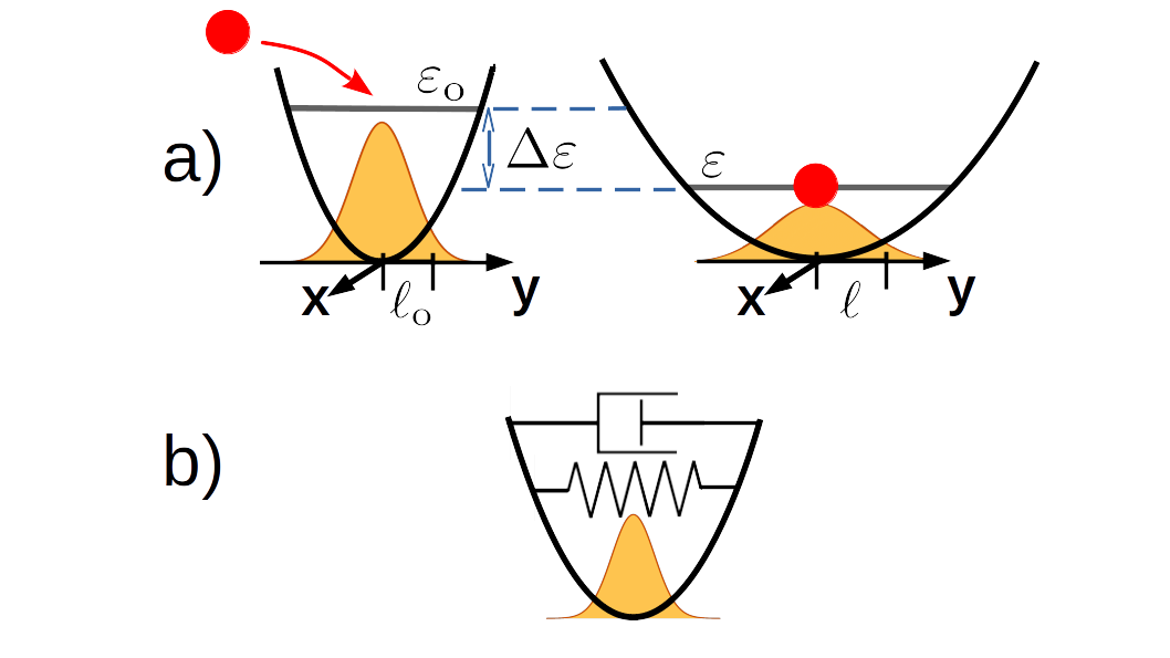
We describe the coherent coupling between the electron-hole states and the fundamental intra-molecular vibrational mode via the Ehrenfest method. In this model the semiclassical electron-phonon system is equivalent to a spring-damper hybrid quantum-classical system, as shown in Figure S1-b) The classical Hamiltonian describing the vibrational mode of site is given by
| (S6) |
where is the vibrational coordinate associated with the molecular site and is the conjugate momentum. In addition, is the confinement length for an empty (that is, neutral) site, is the effective mass of the vibrational mode and is the frequency of the relevant normal mode. Refer to Table 1 in the paper for a complete list of model parameters. The energy is the work exchanged with the electronic degrees of freedom via the Ehrenfest force and is the heat exchanged with the classical thermostat. A similar hamiltonian has been considered by Egorova et al.Egorova et al. (2001, 2003) for quantum intra-molecular degrees of freedom. The Ehrenfest force that acts on the vibrational coordinate of a given molecular site is
| (S7) |
with and . Solving equation (S7) we obtainAndermann and Rego (2022)
| (S8) |
The first term on the right-hand side (RHS) of Equation (S8) is responsible for the relaxation of the molecular site due to its charge occupation; this is the classical work exchanged between electronic and vibrational degrees of freedom. The second term gives rise to coherent vibronic effects, for it is proportional to the off-diagonal elements of and couples the electronic and nuclear coordinates via .Sachtleben et al. (2017)
The classical equations of motion derived from Eq. (S6) are solved with the velocity Verlet algorithm, coupled to a classical bath, described by the Berendsen thermostat,Berendsen et al. (1984) with relaxation constant ps. The perturbing forces change the equilibrium configuration of the parabolic confining potential, which reacts with a restoring force .
II Vibronic Recombination Model
In order to compare the vibronic recombination model with the three-state recombination model,Coropceanu et al. (2019); Benduhn et al. (2017); Qian et al. (2018); Eisner et al. (2019); Chen et al. (2021) let us consider the dynamical equation for recombination, Eq. (6), in the paper
| (S9) |
where
| (S10) |
so that we obtain the following set of coupled equations
| (S11) | |||||
| (S12) |
For the sake of simplifying the argument we are assuming here that the electron and hole states are described by wavefunctions. However, in our treatment the electron and hole states are described by reduced density matrices because of the system-bath interaction. So, let us consider the matrix element that gives rise to the recombination of electrons due to the operator
| (S13) |
Substituting Eq. (S13) into the previous matrix element and writing the electron and hole wavepackets in the molecular site basis, , we get
| (S14) | |||||
| (S15) |
where as given by Eq. (5) of the paper. This expression can be compared with the three-state model. The first term describes the radiative recombination taking place on molecular site , and can be associated with the radiative decay constant, since it does not depend on temperature or vibrational motion. The second term couples distinct molecular sites. For instance, a hole in the donor site is coupled to electrons in both donor and acceptor sites via , which is the vibronic coupling term that depends on the temperature. This term is a generalization of the LE-CT hybridization considered in the three-state model. However, the choice of a single recombination parameter , associated with the el-hl lifetime, for both contributions is clearly an oversimplification. Previous studies have treated differently for radiative and non-radiate recombination processes. For instance, Coropceanu and collaboratorsCoropceanu et al. (2019); Chen et al. (2021) associate with the Einstein spontaneous emission rate for the radiative recombination term whereas the Marcus-Levich-Jortner (MLJ) formula was used to define the non-radiative decay rate . The interplay of charge transfer and non-radiative decay was investigated by atomistic non-adiabatic molecular dynamics simulations in dye-sensitized semiconductor interfaces,Rego and Bortolini (2019) where it was revealed a rate competition between the two mechanisms.
Finally, it is worth noting that Eq. (S15) describes the recombination losses during the exciton diffusion and during the life-time of the CT state at the D:A interface.
III Supporting Simulation Results
III.1 Electron-Hole Interaction and Recombination
III.2 Vibrational Dynamics and Recombination
III.3 Charge Generation with and without Recombination
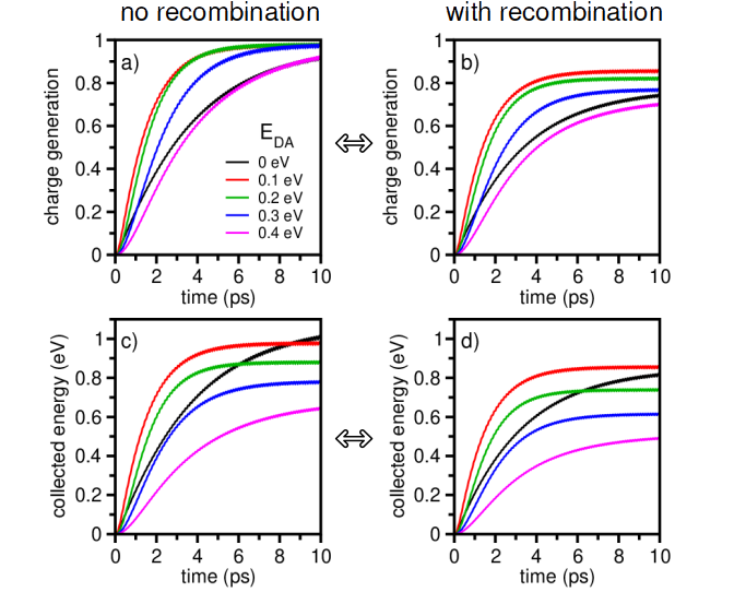
By comparing the LHS (no recombination) with the RHS (with recombination) panels of Figure S4, we observe that both the charge separation and energy conversion efficiencies decrease as a consequence of recombination for all values of the driving force . For each case, the photovoltaic energy conversion decreased by: 19% ( 190 meV) for = 0 (black), 12% ( 120 meV) for = 0.1 eV (red), 16% ( 140 meV) for = 0.2 eV (green), 21% ( 160 meV) for = 0.3 eV (blue) and 24% ( 150 meV) for = 0.4 eV (magenta). The results show that for the activationless regime ( = 100 meV ) the losses due to recombination are minimized, since charge separation is more efficient in this regime.Andermann and Rego (2022) As the driving force increases, for = 0.2, 0.3 and 0.4 eV, and the system enters the Marcus inverted regime for charge separation, the losses due to recombination increase. We ascribe this effect to reduced charge separation, as the driving force exceeds to the reorganization energy at the interface. Here the combination of big energetic driving forces and increased recombination renders the overall energy loss for = 0.4 eV the highest of all cases, followed by = 0.3 and 0.2 eV, respectively. However, the biggest energy loss due exclusively to recombination (in absolute value) occurs for = 0, because of the much slower electron-hole pair separation rate without the energetic driving force. Internal electric fields should improve considerably the power conversion efficiency at vanish driving forces. The simulation results indicate that the condition has the effect of minimizing the effects of the geminate recombination.