Electron charge qubit with 0.1 millisecond coherence time
Abstract
Electron charge qubits are compelling candidates for solid-state quantum computing because of their inherent simplicity in qubit design, fabrication, control, and readout. However, all existing electron charge qubits, built upon conventional semiconductors and superconductors, suffer from severe charge noise that limits the coherence time to the order of 1 microsecond. Here, we report our experimental realization of ultralong-coherence electron charge qubits, based upon isolated single electrons trapped on an ultraclean solid neon surface in vacuum. Quantum information is encoded in the motional states of an electron that is strongly coupled with microwave photons in an on-chip superconducting resonator. The measured relaxation time and coherence time are both on the order of 0.1 milliseconds. The single-shot readout fidelity without using a quantum-limited amplifier is 98.1%. The average single-qubit gate fidelity using Clifford-based randomized benchmarking is 99.97%. Simultaneous strong coupling of two qubits with the same resonator is demonstrated, as a first step toward two-qubit entangling gates for universal quantum computing. These results manifest that the electron-on-solid-neon (eNe) charge qubits outperform all existing charge qubits to date and rival state-of-the-art superconducting transmon qubits, offering an appealing platform for quantum computing.
Quantum bits (qubits) are the fundamental building blocks in quantum information processing. A key measure of a qubit’s performance is its coherence time, which describes how long a superposition between two quantum states and can persist [1]. Among a handful of on-chip solid-state qubits today [2, 3], a coherence time on the order of 0.1 ms or longer has only been achieved in semiconductor quantum-dot and donor qubits based on electron spins [4, 5, 6, 7], and superconducting transmon and fluxonium qubits based on capacitively and inductively shunted Josephson junctions [8, 9, 10, 11]. By contrast, the coherence time in the traditional semiconductor quantum-dot qubits and superconducting Cooper-pair-box (CPB) qubits based on electron charges (motional states) is at most on the order of s [4, 12]. Given that a typical gate time is around 10 ns in such systems, in order to make electron charge qubits serious contenders for quantum computing, it is imperative to increase their coherence time to at least the order of 0.1 ms, that is, a ratio between the coherence and gate times [13].
The short coherence time for conventional electron charge qubits is commonly recognized as a result of their high sensitivity to environmental noise, e.g., charge fluctuations in ordinary host materials [14, 7]. Nonetheless, if their coherence time can be substantially prolonged, electron charge qubits will possess unique advantages: (i) They can be conveniently designed and fabricated with no need of spin-purified substrates [6] or patterned micromagnets [15], significantly reducing the manufacturing cost [16]. (ii) They can be fully electrically controlled with no involvement of magnetic fields [17], intrinsically eliminating the compatibility issues between magnetic fields and superconducting circuits [18, 19]. (iii) They can be individually addressed and readout by microwave photons owing to the much stronger coupling between an electric dipole and electric field than a magnetic dipole and magnetic field [20, 4], fundamentally avoiding the complexities of high microwave power [21] or spin-charge conversion [22, 15].
In this paper, we report our experimental realization of unconventional electron charge qubits with 0.1 ms long coherence time, based upon single electrons trapped on a solid neon surface [23]. Neon (Ne), as a noble-gas element, is inert against forming chemical bonds with any other elements. In a low-temperature and near-vacuum environment, it spontaneously condenses into an ultrapure semi-quantum solid [24] devoid of any two-level-system (TLS) fluctuators, quasiparticles, or dangling bonds that are present in most ordinary materials [17, 25]. Its small atomic polarizability and negligible spinful isotopes make it akin to vacuum with minimal charge and spin noise for electron qubits [24, 26]. By integrating an electron trap in a superconducting quantum circuit, the charge (motional) states of an electron can be controlled and readout by microwave photons in an on-chip resonator. Our previous demonstration of the electron-on-solid-neon (eNe) qubit platform has shown an appreciable relaxation time of 15 s and coherence time of 220 ns [23].
Here we successfully extend both and into 0.1 ms time scale by making three critical advancements: (i) annealing solid Ne to pursue the best surface quality, (ii) stabilizing the electron trapping potential to ensure the lowest ( Hz) background noise, and (iii) operating the qubit at charge-noise-insensitive (sweet) spots. With 0.1 ms long coherence time, we manage to perform single-shot readout of the qubit states [27] and obtain a 98.1 % readout fidelity without using a quantum-limited amplifier. This is on par with the readout fidelity of the state-of-the-art transmon qubits with a similar amplification chain [27, 28]. We further manage to perform Clifford-based randomized benchmarking [29] and obtain an average single-qubit gate fidelity of 99.97 %, which is well above the fault-tolerance threshold for quantum error correction with surface codes [30]. Moreover, we manage to simultaneously couple two electron qubits with the same resonator, as a first step toward two-qubit entangling gates for universal quantum computing [31]. These results manifest that the eNe charge qubits outperform all traditional semiconductor and superconducting charge qubits and rival the best superconducting transmon qubits today.

Qubit design
The eNe qubit is situated in an electron trap in a niobium (Nb) superconducting quantum circuit that is fabricated on an intrinsic silicon (Si) substrate, as shown in Fig. Electron charge qubit with 0.1 millisecond coherence timea. A channel of 3.5 m in width and 1 m in depth is etched into the substrate. A quarter-wavelength double-stripline microwave resonator runs on the bottom through the channel. A dc electrode, called the trap, also runs on the bottom, but from the other end of the channel into the open end of the resonator. The channel, resonator, and trap are all deformed into oval shapes in the trapping region to accommodate the desired functionalities as described below. On the ground plane outside the channel, four additional dc electrodes, made into two pairs and called the resonator-guards and trap-guards respectively, surround the trapping region. The dc bias voltages applied to these dc electrodes, as well as the resonator with a tuning-fork structure [32], tune the trapping potential. We ensures the lowest charge noise from our apparatus by using an ultra-stable high-precision digital-to-analog converter (DAC) at room temperature and lowpass filters with 10 Hz cutoff frequency at mK temperature.
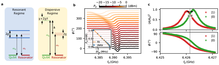
The qubit states and are defined by the electron’s motional (charge) states, i.e., the ground state and the first excited state respectively, in the -direction across the channel. The electric dipole transition between and strongly couples with the electric field, which points from one stripline to the other, of the microwave photons in the antisymmetric (differential) mode of the resonator [32, 23]. The bare resonator frequency, defined after neon filling but before electron-photon coupling, is GHz. The resonator linewidth is MHz, which is dominated by the input and output photon coupling. All the microwave measurements are done in a transmission configuration through the resonator.
We fill a controlled amount of liquid Ne into the sample cell, using a homemade gas-handling puff system, to wet the channel and quantum circuit at around 26 K. We cool the system down along the liquid-vapor coexistence line and turn the liquid into solid by passing the solid-liquid-gas triple point at the temperature K and pressure bar [33]. We hold the temperature at 10 K for 1 – 2 hours to anneal the solid and smooth out the surface [34], and then continuously cool down to the base temperature around 10 mK for experiments. The thickness of solid Ne that covers the trapping region is estimated to be tens of nanometers. Electrons are emitted from a heated tungsten filament above the quantum circuit and are trapped on the solid Ne surface under the combined actions of natural surface potential and applied electric potential [24, 35, 36, 23].
Qubit spectroscopy
We first verify the strong coupling between a trapped single electron and microwave photons in the circuit quantum electrodynamics (cQED) architecture (see Methods). By varying the resonator-guard voltage and keeping all other voltages fixed, we tune the qubit frequency across . The normalized transmission amplitude through the resonator is plotted in Fig. Electron charge qubit with 0.1 millisecond coherence timeb. Two avoided crossings, known as the vacuum Rabi splitting, can be clearly seen. A line cut in Fig. Electron charge qubit with 0.1 millisecond coherence timeb at the on-resonance condition , marked by the pink arrows, is plotted in Fig. Electron charge qubit with 0.1 millisecond coherence timec. By fitting the curve with the input-output theory, we obtain the electron-photon (qubit-resonator) coupling strength MHz, and the on-resonance qubit linewidth MHz. The fact that indicates that the qubit and resonator are strongly coupled. In this vacuum Rabi splitting measurement, the average intra-resonator photon number is kept below 1, as can be verified by the ac Stark effect [37] (see Methods).
We use two-tone qubit spectroscopy to reveal the qubit spectrum tuned by , as plotted in Fig. Electron charge qubit with 0.1 millisecond coherence timed. The dependence of on can be identified as the white curve, where the drive frequency hits and induces a sudden phase shift. The spectrum suggests that is nearly a quadratic function of and contains a minimum at the so-called charge sweet spot, as indicated by the yellow arrow. On this spot, where GHz and mV, the charge qubit is first-order insensitive to the low-frequency charge noise and holds the longest coherence time along the spectrum [38].
State control and readout
We perform real-time state control and readout on the eNe qubit in the dispersive regime. Rabi oscillations [39] are observed by driving the qubit on the sweet spot, using Gaussian-shaped microwave pulses with fixed frequency and amplitude , and variable pulse duration . The oscillations of qubit states detected by dispersive readout [20] (see Methods) are plotted in two (short and long) time scales in Fig. Electron charge qubit with 0.1 millisecond coherence timee. The Rabi decay time s is obtained by an exponential fit to the envelope of oscillatory population in the excited state in the large time scale. Such a long indicates both a long relaxation time and a long pure-dephasing time , the latter of which is related to the total coherence time via . Theoretically, in the absence of inhomogeneous broadening and under a strong driving electric field, is related to and by [40, 41].
Relaxation and coherence times
We then find the characteristic times of the eNe qubit, i.e., the relaxation time , the total dephasing (Ramsey) time , and the total coherence time with a Hahn echo . These characteristic times provide key measures of single-qubit performance.
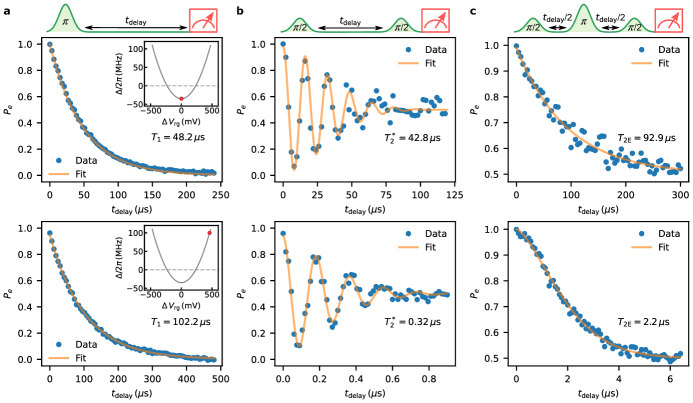
The total relaxation (decay) rate is the sum of radiative decay rate , which is determined by the Purcell effect [42, 43], and nonradiative decay rate . On the sweet spot, the measured is s, as shown in the upper panel of Fig. Electron charge qubit with 0.1 millisecond coherence timea. With the known values of , , and MHz on the sweet spot, we find a radiative decay time s and nonradiative decay time s. This suggests that the Purcell-limited radiative decay is the dominant decay channel here. We verify this by purposely moving away from the sweet spot to a point with a larger detuning, MHz. It gives an even longer of s, as shown in the lower panel of Fig. Electron charge qubit with 0.1 millisecond coherence timea, which agrees with the sum of the estimated at this detuning and the above.
On the sweet spot, the first-order insensitivity of the qubit frequency to the low-frequency charge noise yields exceedingly long total dephasing time and total coherence time with a Hahn echo . Our Ramsey-fringe measurement gives a s, as shown in the upper panel of Fig. Electron charge qubit with 0.1 millisecond coherence timeb. To our knowledge, this is the longest observed charge-qubit dephasing time, compared with all existing semiconductor quantum-dot and superconducting CPB charge qubits [11, 44, 3, 2]. The low-frequency noise can be further suppressed by applying echo pulses. Our Hahn-echo measurement gives a s that almost equals , as shown in the upper panel of Fig. Electron charge qubit with 0.1 millisecond coherence timec. This means that, on the sweet spot, the residual decoherence that cannot be mitigated by Hahn echoes is dominated by relaxation. As a comparison, we purposely move off the sweet spot to a point more sensitive to charge noise at MHz detuning. The observed decreases to s and decreases to s, as shown in the lower panels of Fig. Electron charge qubit with 0.1 millisecond coherence timeb and Electron charge qubit with 0.1 millisecond coherence timec.
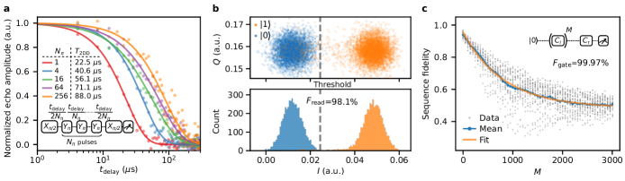
For the completeness of our investigation, we slightly change the Ne thickness and make another eNe qubit that has a larger detuning on the sweet spot, MHz, which more strongly suppresses the Purcell-limited radiative decay. This qubit shows a much longer s but shorter s. However, we successfully utilize the Carr-Purcell-Meiboom-Gill (CPMG) dynamical-decoupling (DD) pulse sequence to push a DD coherence time also into 0.1 ms time scale. As shown in Fig. Electron charge qubit with 0.1 millisecond coherence timea, with the number of pulses (equivalent to one echo pulse), s, and with , , , , , , , s. While systematic analysis of the qubit noise spectra and their correlation with solid Ne quality is underway, the above observations evidence that solid Ne can indeed serve as a superior host material for electron qubits.
Readout and gate fidelities
We then determine the readout and gate fidelities in the eNe qubit system. The qubit with a long s on the sweet spot allows us to use long (s) readout pulses without relying on a quantum-limited amplifier. Figure Electron charge qubit with 0.1 millisecond coherence timeb shows the distribution of single-shot readout values for the qubit states prepared in or . It yields a single-shot readout fidelity [45]. This is higher than the reported of superconducting transmon qubits with a similar amplification chain [27, 28].
The single-qubit gate fidelity for the same qubit is found by Clifford-based randomized benchmarking technique [29, 46]. In this protocol, a Clifford gate sequence with an increasing number of random Clifford gates and one recovery gate is applied to the qubit in the ground state. Each gate pulse has a Gaussian shape truncated at 2.5 standard deviation ( ns) on each side. A separation time of 20 ns is inserted between every two nearest pulses. The decay of the mean sequence fidelity versus gives an estimate of the average single-qubit gate fidelity , as shown in Fig. Electron charge qubit with 0.1 millisecond coherence timec, that is well over the threshold for quantum error correction with surface codes [30].
Two qubits strong coupling
Beyond the accomplished single-qubit operations, we are able to load two qubits onto the same trap and spectroscopically bring them on and off resonance with the resonator and show strong coupling for each of them. This is the first step to achieve two-qubit entangling gates in a cQED architecture.
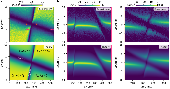
We tune the two qubits by concurrently varying two independent parameters: the offset resonator voltage and the resonator-guard voltage . We call the qubit with larger coupling strength as qubit-1 and the other as qubit-2. Their frequencies and have different voltage dependence. The upper row of Fig. Electron charge qubit with 0.1 millisecond coherence time displays the experimental measurements of the normalized transmission amplitude of the resonator at the bare resonance frequency, with variable and . With obtained qubits properties from the experiments, theoretical calculations based on the Tavis-Cummings model [47] and the input-output formalism [48] (see Methods) show excellent agreement with the experiments, as plotted in the lower row.
The two dark lines in Fig. Electron charge qubit with 0.1 millisecond coherence timea indicate the qubit-resonator on-resonance condition, and , respectively. The parameter space (, ) is divided by the two dark lines into four regions: , , , and . A notable feature is that is smaller in the and two regions, compared with the other regions. In these two regions, both qubits push the resonator frequency in the same direction due to the strong qubits-resonator coupling, resulting a larger resonator frequency shift and thus a smaller transmission amplitude, as verified by the theoretical calculation.
Figure Electron charge qubit with 0.1 millisecond coherence timeb shows the system spectrum when the two qubits are individually brought onto resonance with the resonator by a tunable and a fixed mV, as indicated by the magenta arrows in Fig. Electron charge qubit with 0.1 millisecond coherence timea. We can retrieve the coupling strength MHz, MHz, and the qubit linewidth MHz, MHz from the individual vacuum Rabi splitting. Figure Electron charge qubit with 0.1 millisecond coherence timec shows the system spectrum when the two qubits are simultaneously brought onto resonance with the resonator by a tunable and another fixed mV, as indicated by the orange arrows in Fig. Electron charge qubit with 0.1 millisecond coherence timea. At mV, the resonator is simultaneously hybridized with both qubits.
Discussion and outlook
While our measured coherence time for an eNe qubit has approached 0.1 ms, we believe that it can be further improved by optimizing our device design, drive scheme, and solid-Ne growth procedure. Solely from the material perspective, we do not foresee a practical limit on the charge-qubit coherence time in this system, though theoretical calculation can be done to find out the ultimate decoherence due to thermal phonons or quantum zero-point motion of Ne atoms [49, 50, 51, 52].
The anharmonicity , defined as the frequency difference between the and transitions with being the second excited state, is a critical parameter for the gate time. A larger ensures a shorter gate time [39]. For our qubit, is estimated to be greater than GHz, based on the large detuning range and strong pumping power that we have explored. We were not able to observe a two-photon transition or a one-photon transition after preparing the qubit on . We shall note that even for an infinite , which corresponds to an ideal two-level system, the theoretical dispersive shift would be MHz, which is close to our measured MHz. This is another evidence that our is very larger, .
While we have managed to simultaneously couple two electron qubits to the same resonator, to realize two-qubit gates in real time in the cQED architecture, we need to push on from the strong resonant regime into the strong dispersive regime. This requires larger and [53]. In light of the observed MHz at the charge sweet spot, already satisfies the strong dispersive requirement. To keep fast operations, the resonator linewidth from the input-output coupling cannot be much smaller than the current MHz. Therefore, the coupling strength should be enhanced by about ten times, optimally. This may be fulfilled by using high kinetic-inductance superconducting materials for the on-chip resonator [54, 55, 56]. Realization of two-qubit gates in the eNe charge qubit platform will establish a further milestone toward universal quantum computing.
References
- Ladd et al. [2010] T. D. Ladd, F. Jelezko, R. Laflamme, Y. Nakamura, C. Monroe, and J. L. O’Brien, “Quantum computers,” Nature 464, 45–53 (2010).
- Chatterjee et al. [2021] A. Chatterjee, P. Stevenson, S. De Franceschi, A. Morello, N. P. de Leon, and F. Kuemmeth, “Semiconductor qubits in practice,” Nat. Rev. Phys. 3, 157–177 (2021).
- Siddiqi [2021] I. Siddiqi, “Engineering high-coherence superconducting qubits,” Nat. Rev. Mater. 6, 875–891 (2021).
- Stano and Loss [2022] P. Stano and D. Loss, “Review of performance metrics of spin qubits in gated semiconducting nanostructures,” Nat. Rev. Phys. 4, 672–688 (2022).
- Muhonen et al. [2014] J. T. Muhonen, J. P. Dehollain, A. Laucht, F. E. Hudson, R. Kalra, T. Sekiguchi, K. M. Itoh, D. N. Jamieson, J. C. McCallum, A. S. Dzurak, and A. Morello, “Storing quantum information for 30 seconds in a nanoelectronic device,” Nat. Nanotechnol. 9, 986–991 (2014).
- Veldhorst et al. [2014] M. Veldhorst, J. C. Hwang, C. H. Yang, A. W. Leenstra, B. De Ronde, J. P. Dehollain, J. T. Muhonen, F. E. Hudson, K. M. Itoh, A. Morello, and A. S. Dzurak, “An addressable quantum dot qubit with fault-tolerant control-fidelity,” Nat. Nanotechnol. 9, 981–985 (2014).
- Yoneda et al. [2018] J. Yoneda, K. Takeda, T. Otsuka, T. Nakajima, M. R. Delbecq, G. Allison, T. Honda, T. Kodera, S. Oda, Y. Hoshi, N. Usami, K. M. Itoh, and S. Tarucha, “A quantum-dot spin qubit with coherence limited by charge noise and fidelity higher than 99.9%,” Nat. Nanotechnol. 13, 102–106 (2018).
- Nguyen et al. [2019] L. B. Nguyen, Y. H. Lin, A. Somoroff, R. Mencia, N. Grabon, and V. E. Manucharyan, “High-coherence fluxonium qubit,” Phys. Rev. X 9, 041041 (2019).
- Somoroff et al. [2021] A. Somoroff, Q. Ficheux, R. A. Mencia, H. Xiong, R. V. Kuzmin, and V. E. Manucharyan, “Millisecond coherence in a superconducting qubit,” arXiv:2103.08578 (2021).
- Place et al. [2021] A. P. Place, L. V. Rodgers, P. Mundada, B. M. Smitham, M. Fitzpatrick, Z. Leng, A. Premkumar, J. Bryon, A. Vrajitoarea, S. Sussman, G. Cheng, T. Madhavan, H. K. Babla, X. H. Le, Y. Gang, B. Jäck, A. Gyenis, N. Yao, R. J. Cava, N. P. de Leon, and A. A. Houck, “New material platform for superconducting transmon qubits with coherence times exceeding 0.3 milliseconds,” Nat. Commun. 12, 1779 (2021).
- Wang et al. [2022] C. Wang, X. Li, H. Xu, Z. Li, J. Wang, Z. Yang, Z. Mi, X. Liang, T. Su, C. Yang, G. Wang, W. Wang, Y. Li, M. Chen, C. Li, K. Linghu, J. Han, Y. Zhang, Y. Feng, Y. Song, T. Ma, J. Zhang, R. Wang, P. Zhao, W. Liu, G. Xue, Y. Jin, and H. Yu, “Towards practical quantum computers: transmon qubit with a lifetime approaching 0.5 milliseconds,” npj Quantum Inf. 8, 3 (2022).
- Heinrich et al. [2021] A. J. Heinrich, W. D. Oliver, L. M. Vandersypen, A. Ardavan, R. Sessoli, D. Loss, A. B. Jayich, J. Fernandez-Rossier, A. Laucht, and A. Morello, “Quantum-coherent nanoscience,” Nat. Nanotechnol. 16, 1318–1329 (2021).
- Nielsen and Chuang [2010] M. A. Nielsen and I. L. Chuang, Quantum Computation and Quantum Information (Cambridge University Press, 2010).
- Kim et al. [2015] D. Kim, D. R. Ward, C. B. Simmons, J. K. Gamble, R. Blume-Kohout, E. Nielsen, D. E. Savage, M. G. Lagally, M. Friesen, S. N. Coppersmith, and M. A. Eriksson, “Microwave-driven coherent operation of a semiconductor quantum dot charge qubit,” Nat. Nanotechnol. 10, 243–247 (2015).
- Takeda et al. [2016] K. Takeda, J. Kamioka, T. Otsuka, J. Yoneda, T. Nakajima, M. R. Delbecq, S. Amaha, G. Allison, T. Kodera, S. Oda, and S. Tarucha, “A fault-tolerant addressable spin qubit in a natural silicon quantum dot,” Sci. Adv. 2, e1600694 (2016).
- Osman et al. [2021] A. Osman, J. Simon, A. Bengtsson, S. Kosen, P. Krantz, D. P. Lozano, M. Scigliuzzo, P. Delsing, J. Bylander, and A. Fadavi Roudsari, “Simplified Josephson-junction fabrication process for reproducibly high-performance superconducting qubits,” Appl. Phys. Lett. 118, 064002 (2021).
- Pashkin et al. [2009] Y. A. Pashkin, O. Astafiev, T. Yamamoto, Y. Nakamura, and J. S. Tsai, “Josephson charge qubits: A brief review,” Quantum Inf. Process. 8, 55–80 (2009).
- Samkharadze et al. [2016] N. Samkharadze, A. Bruno, P. Scarlino, G. Zheng, D. DiVincenzo, L. DiCarlo, and L. Vandersypen, “High-kinetic-inductance superconducting nanowire resonators for circuit qed in a magnetic field,” Phys. Rev. Appl. 5, 044004 (2016).
- Kroll et al. [2019] J. Kroll, F. Borsoi, K. Van Der Enden, W. Uilhoorn, D. De Jong, M. Quintero-Pérez, D. Van Woerkom, A. Bruno, S. Plissard, D. Car, E. Bakkers, M. Cassidy, and L. Kouwenhoven, “Magnetic-field-resilient superconducting coplanar-waveguide resonators for hybrid circuit quantum electrodynamics experiments,” Phys. Rev. Appl. 11, 064053 (2019).
- Blais, Grimsmo, and Wallraff [2021] A. Blais, A. L. Grimsmo, and A. Wallraff, “Circuit quantum electrodynamics,” Rev. Mod. Phys. 93, 025005 (2021).
- D’Anjou and Burkard [2019] B. D’Anjou and G. Burkard, “Optimal dispersive readout of a spin qubit with a microwave resonator,” Phys. Rev. B 100, 245427 (2019).
- Hu, Liu, and Nori [2012] X. Hu, Y. Liu, and F. Nori, “Strong coupling of a spin qubit to a superconducting stripline cavity,” Phys. Rev. B 86, 035314 (2012).
- Zhou et al. [2022] X. Zhou, G. Koolstra, X. Zhang, G. Yang, X. Han, B. Dizdar, X. Li, D. Ralu, W. Guo, K. W. Murch, D. I. Schuster, and D. Jin, “Single electrons on solid neon as a solid-state qubit platform,” Nature 605, 46–50 (2022).
- Zavyalov et al. [2005] V. Zavyalov, I. Smolyaninov, E. Zotova, A. Borodin, and S. Bogomolov, “Electron states above the surfaces of solid cryodielectrics for quantum-computing.” J. Low Temp. Phys. 138, 415–420 (2005).
- Wilen et al. [2021] C. D. Wilen, S. Abdullah, N. A. Kurinsky, C. Stanford, L. Cardani, G. D’Imperio, C. Tomei, L. Faoro, L. B. Ioffe, C. H. Liu, A. Opremcak, B. G. Christensen, J. L. DuBois, and R. McDermott, “Correlated charge noise and relaxation errors in superconducting qubits,” Nature 594, 369–373 (2021).
- Leiderer, Kono, and Rees [2016] P. Leiderer, K. Kono, and D. Rees, in Proc. 11th International Conference on Cryocrystals and Quantum Crystals, edited by S. Vasiliev (2016) pp. 67–67.
- Mallet et al. [2009] F. Mallet, F. R. Ong, A. Palacios-Laloy, F. Nguyen, P. Bertet, D. Vion, and D. Esteve, “Single-shot qubit readout in circuit quantum electrodynamics,” Nat. Phys. 5, 791–795 (2009).
- Stefanazzi et al. [2022] L. Stefanazzi, K. Treptow, N. Wilcer, C. Stoughton, C. Bradford, S. Uemura, S. Zorzetti, S. Montella, G. Cancelo, S. Sussman, A. Houck, S. Saxena, H. Arnaldi, A. Agrawal, H. Zhang, C. Ding, and D. I. Schuster, “The QICK (Quantum Instrumentation Control Kit): Readout and control for qubits and detectors,” Rev. Sci. Instrum. 93, 044709 (2022).
- Knill et al. [2008] E. Knill, D. Leibfried, R. Reichle, J. Britton, R. B. Blakestad, J. D. Jost, C. Langer, R. Ozeri, S. Seidelin, and D. J. Wineland, “Randomized benchmarking of quantum gates,” Phys. Rev. A 77, 012307 (2008).
- Fowler et al. [2012] A. G. Fowler, M. Mariantoni, J. M. Martinis, and A. N. Cleland, “Surface codes: Towards practical large-scale quantum computation,” Phys. Rev. A 86, 032324 (2012).
- Divincenzo et al. [2000] D. P. Divincenzo, D. Bacon, J. Kempe, G. Burkard, and K. B. Whaley, “Universal quantum computation with the exchange interaction,” Nature 408, 339–342 (2000).
- Koolstra, Yang, and Schuster [2019] G. Koolstra, G. Yang, and D. I. Schuster, “Coupling a single electron on superfluid helium to a superconducting resonator,” Nat. Commun. 10, 5323 (2019).
- Jacobsen, Penoncello, and Lemmon [1997] R. T. Jacobsen, S. G. Penoncello, and E. W. Lemmon, “Thermodynamic properties of cryogenic fluids,” in Thermodynamic Properties of Cryogenic Fluids (Springer, 1997) pp. 31–287.
- Mugele et al. [1992] F. Mugele, U. Albrecht, P. Leiderer, and K. Kono, “Possible correlation effects of surface state electrons on a solid hydrogen film,” J. Low Temp. Phys. 89, 743–746 (1992).
- Schuster et al. [2010] D. I. Schuster, A. Fragner, M. I. Dykman, S. A. Lyon, and R. J. Schoelkopf, “Proposal for manipulating and detecting spin and orbital states of trapped electrons on helium using cavity quantum electrodynamics,” Phys. Rev. Lett. 105, 040503 (2010).
- Kawakami, Elarabi, and Konstantinov [2019] E. Kawakami, A. Elarabi, and D. Konstantinov, “Image-charge detection of the rydberg states of surface electrons on liquid helium,” Phys. Rev. Lett. 123, 086801 (2019).
- Schuster et al. [2005] D. I. Schuster, A. Wallraff, A. Blais, L. Frunzio, R. S. Huang, J. Majer, S. M. Girvin, and R. J. Schoelkopf, “ac Stark shift and dephasing of a superconducting qubit strongly coupled to a cavity field,” Phys. Rev. Lett. 94, 123602 (2005).
- Vion et al. [2002] D. Vion, A. Aassime, A. Cottet, P. Joyez, H. Pothier, C. Urbina, D. Esteve, and M. H. Devoret, “Manipulating the quantum state of an electrical circuit,” Science 296, 886–889 (2002).
- Krantz et al. [2019] P. Krantz, M. Kjaergaard, F. Yan, T. P. Orlando, S. Gustavsson, and W. D. Oliver, “A quantum engineer’s guide to superconducting qubits,” Appl. Phys. Rev. 6, 021318 (2019).
- Allen and Eberly [1987] L. Allen and J. H. Eberly, Optical Resonance and Two-Level Atoms (Dover, New York, 1987).
- Bianchetti et al. [2009] R. Bianchetti, S. Filipp, M. Baur, J. M. Fink, M. Göppl, P. J. Leek, L. Steffen, A. Blais, and A. Wallraff, “Dynamics of dispersive single-qubit readout in circuit quantum electrodynamics,” Phys. Rev. A 80, 043840 (2009).
- Purcell [1946] E. M. Purcell, “Spontaneous emission probabilities at radio frequencies,” Phys. Rev. 69, 681 (1946).
- Sete, Gambetta, and Korotkov [2014] E. A. Sete, J. M. Gambetta, and A. N. Korotkov, “Purcell effect with microwave drive: Suppression of qubit relaxation rate,” Phys. Rev. B 89, 104516 (2014).
- Verjauw et al. [2022] J. Verjauw, R. Acharya, J. Van Damme, T. Ivanov, D. P. Lozano, F. Mohiyaddin, D. Wan, J. Jussot, A. Vadiraj, M. Mongillo, M. Heyns, I. Radu, B. Govoreanu, and A. Potočnik, “Path toward manufacturable superconducting qubits with relaxation times exceeding 0.1 ms,” arXiv:2202.10303 (2022).
- Gambetta et al. [2007] J. Gambetta, W. A. Braff, A. Wallraff, S. M. Girvin, and R. J. Schoelkopf, “Protocols for optimal readout of qubits using a continuous quantum nondemolition measurement,” Phys. Rev. A 76, 012325 (2007).
- Barends et al. [2014] R. Barends, J. Kelly, A. Megrant, A. Veitia, D. Sank, E. Jeffrey, T. C. White, J. Mutus, A. G. Fowler, B. Campbell, Y. Chen, Z. Chen, B. Chiaro, A. Dunsworth, C. Neill, P. O’Malley, P. Roushan, A. Vainsencher, J. Wenner, A. N. Korotkov, A. N. Cleland, and J. M. Martinis, “Superconducting quantum circuits at the surface code threshold for fault tolerance,” Nature 508, 500–503 (2014).
- Tavis and Cummings [1968] M. Tavis and F. Cummings, “Exact solution for an n-molecule-radiation-field hamiltonian,” Phys. Rev. 170, 379–384 (1968).
- Walls and Milburn [2007] D. F. Walls and G. J. Milburn, Quantum Optics (Springer Science & Business Media, 2007).
- Dykman, Platzman, and Seddighrad [2003] M. I. Dykman, P. M. Platzman, and P. Seddighrad, “Qubits with electrons on liquid helium,” Phys. Rev. B 67, 155402 (2003).
- Chen et al. [2022] Q. Chen, I. Martin, L. Jiang, and D. Jin, “Electron spin coherence on a solid neon surface,” Quantum Sci. and Technol. 7, 045016 (2022).
- Pollack [1964] G. L. Pollack, “The solid state of rare gases,” Rev. Mod. Phys. 36, 748 (1964).
- Klein and Venables [1976] M. L. Klein and J. A. Venables, Rare Gas Solids, Vol. I (Academic, New York, 1976).
- D. I. Schuster [2007] D. I. Schuster, Circuit Quantum Electrodynamics, Ph.D. thesis, Yale University (2007).
- Shearrow et al. [2018] A. Shearrow, G. Koolstra, S. J. Whiteley, N. Earnest, P. S. Barry, F. J. Heremans, D. D. Awschalom, E. Shirokoff, and D. I. Schuster, “Atomic layer deposition of titanium nitride for quantum circuits,” Appl. Phys. Lett. 113, 212601 (2018).
- Xu et al. [2019] M. Xu, X. Han, W. Fu, C.-L. Zou, and H. X. Tang, “Frequency-tunable high-q superconducting resonators via wireless control of nonlinear kinetic inductance,” Appl. Phys. Lett. 114, 192601 (2019).
- Han et al. [2022] X. Han, C.-L. Zou, W. Fu, M. Xu, Y. Xu, and H. X. Tang, “Superconducting cavity electromechanics: The realization of an acoustic frequency comb at microwave frequencies,” Phys. Rev. Lett. 129, 107701 (2022).
Methods
Qubit-resonator coupled system
Our electron-photon (qubit-resonator) coupled system adopts a cQED architecture. When the qubit and resonator are uncoupled, the qubit has its bare frequency . In the presence of a finite coupling strength , the eigenstates of the coupled system are dressed states [20]. As plotted in Extended Data Fig.1a, in the resonant regime, , the qubit and resonator maximally hybridize, and a vacuum Rabi splitting 2 opens up. In the dispersive regime, the detuning , the actual qubit frequency acquires a shift of , in which is called the dispersive shift, is called the ac Stark shift, and is the average intra-resonator photon number. In this regime, the actual resonator frequency acquires a or shift, when the qubit is kept in the excited or ground state, respectively.
ac Stark effect
We use the two-tone qubit spectroscopy to demonstrate the ac Stark effect and calibrate the average intra-resonator photon number . Keeping on the sweet spot and the drive power low, we scan both the drive frequency and the probe power . In this scenario, increases with the increasing and the qubit frequency shifts under the ac Stark effect [37]. Extended Data Fig.1b gives a series of curves of versus with step-increased . The detected is red-shifted by MHz when (from the vector network analyzer) is increased from dBm to 0 dBm. This shift is related to the average intra-resonator photon number by [37]. Through this measurement, and the measurement of (see below), we know that a probe power dBm mW (about dBm reaching the sample) corresponds to .
Dispersive readout
The qubit readout follows the standard dispersive readout scheme, where the qubit states are inferred from measuring the phase or amplitude shift of the transmission through the resonator. The readout is performed with . As shown in Extended Data Fig.1c, the resonator frequency is dispersively shifted to or , when the qubit is in the excited state or ground state . Here on the sweet spot, we have MHz. The dispersive readout has the highest contrast by fixing the probe frequency at the bare resonance frequency indicated by the gray line, where the phase separation between and is maximal.
Theoretical modeling of two qubits coupling
The behavior of a system consisting of two qubits interacting with a single-mode resonator can be theoretically described by the Tavis-Cummings (TC) Hamiltonian in the rotating-wave approximation [47],
| (1) |
where and is the resonator frequency, and are the creation and annihilation operators of microwave photons, is the qubit frequency, and is the coupling strength between the qubit and the resonator, and are the ladder operators acting on the qubit .
Using the quantum master equation and input-output theory [48], assisted with the known quantities directly measured from experiments, such as the resonator linewidth , we can theoretically calculate all the normalized transmission amplitude through the resonator versus the qubit frequency and probe frequency . The only phenomenological modeling necessary is the relations between the qubit frequencies and applied voltages, which we assume to be linear functions.
Data availability
The raw data that support the findings of this study are available from the corresponding author upon reasonable request.
Code availability
The codes used to perform the experiments and to analyze the data in this work are available from the corresponding author upon reasonable request.
Acknowledgements.
Work performed at the Center for Nanoscale Materials, a U.S. Department of Energy Office of Science User Facility, was supported by the U.S. DOE, Office of Basic Energy Sciences, under Contract No. DE-AC02-06CH11357. D.J., X.H., X.L., and Q.C. acknowledge support from Argonne National Laboratory Directed Research and Development (LDRD). D.J. and X.Zhou acknowledge support from the Julian Schwinger Foundation for Physics Research. This work was partially supported by the University of Chicago Materials Research Science and Engineering Center, which is funded by the National Science Foundation under award number DMR-2011854. This work made use of the Pritzker Nanofabrication Facility of the Institute for Molecular Engineering at the University of Chicago, which receives support from SHyNE, a node of the National Science Foundation National Nanotechnology Coordinated Infrastructure (NSF NNCI-1542205). D.I.S. and B.D. acknowledge support from the National Science Foundation DMR grant DMR-1906003. D.I.S. and C.S.W. acknowledge support from the U.S. Department of Energy, Office of Science, National Quantum Information Science Research Centers. G.Y. acknowledges supports from the National Science Foundation under Cooperative Agreement PHY-2019786 (the NSF AI Institute for Artificial Intelligence and Fundamental Interactions). D.J. thanks Anthony J. Leggett for inspiring discussions. The qubit manipulation and measurement in this work utilized the highly efficient and effective OPX+, Octave, and QDAC-II made by Quantum Machines and QDevil.