Hall effect induced by topologically trivial target skyrmions
Abstract
Electrons moving through a noncoplanar magnetic texture acquire a Berry phase, which can be described as an effective magnetic field. This effect is known as the topological Hall effect and has been observed in topological spin textures. Motivated by recent experimental realizations, here we study the Hall effect in a nontopological magnetic texture known as a target skyrmion. We start from a simplified semiclassical picture and show that the Hall signal is a nonmonotonic function of both the electronic energy and target skyrmion radius. That observation carries over to the fully quantum mechanical treatment in a Landauer-Büttiker formalism in a mesoscopic setting. Our conclusion challenges the popular opinion in the community that the Hall effect in such structures necessarily requires a nonzero skyrmion number.
I Introduction
In contrast to the classical Hall effect [1] induced by a nonzero external magnetic field, the anomalous Hall effect (AHE) represents a component of the Hall signal proportional to the magnetization of a magnet [2, 3]. Therefore it can exist even in the absence of the external magnetic field. In frustrated chiral magnets, there is an additional contribution to AHE arising from the noncoplanar structure of spin magnetic moments [4, 5, 6, 7, 8]. In these materials, electrons acquire a Berry phase, therefore generating an anomalous velocity which can be understood as the Lorentz force of an effective magnetic field in momentum space [2, 3, 4, 5]. More interestingly, in the adiabatic regime where itinerant electrons are strongly coupled to the spins, the Berry curvature in real space can give rise to the AHE effect [9, 10, 11]. This effect is also known as the topological Hall effect (THE). As the real space Berry phase is directly related to the topology of the spin texture, the THE is often used as evidence of nontrivial spin texture [12, 13, 14, 15, 16, 17]. One notable example of nontrivial spin texture is the magnetic skyrmion, whose topological charge (Q = 1) is defined as the integer winding number of spin on a unit sphere [18].
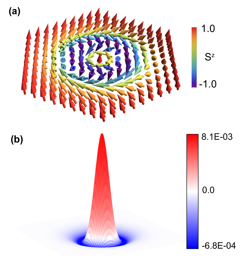
Since the discovery of skyrmions in MnSi[14], the role of topology and magnetization has increasingly expanded for its potential use in dense and robust data storage, as well as racetrack memory for quick data access [19, 20, 21]. However, chiral spin textures that are classified as topologically trivial have remained underexplored in theory and experiment. In particular, the target skyrmion whose texure is a concentric ring of one skyrmion inside another skyrmion with reversed spins (see Fig.1a) can be moved linearly with a current, making it promising for racetrack memory applications [22, 23, 24, 25, 26]. Currently, target skyrmion are being identified by techniques such as magnetic force microscopy, Lorentz transmission electron miscroscopy, X-ray photoelectron spectroscopy, and electron hollography, which can not be integrated to electronic devices [22, 25, 27]. The topological Hall effect, however, can be used to quickly detect presence of spin texture by measuring the transverse voltage of devices. Here we show that the topological trivial target skyrmion can give rise to the Hall effect.
We start with a classical model of electrons traveling in the effective magnetic field of the target skyrmion and show a non-zero transverse current. We then performed quantum transport calculations and observed a sign change in the non-monotonic Hall angle dependence of target skyrmion radii. This indicates the inner and outer skyrmion shells contribute to the Hall angle independently. This result is further supported by the calculation of the Hall angle for each shell; showing that the sum of the Hall angle of each shell is the same as the target skyrmion’s Hall angle. We also shows that our results respect the adiabatic approximation. This implies that the Hall effect came from real space topology, which can be interpreted as the THE.
II Target skyrmion configuration
To set the stage, we discuss details of a target-skyrmion texture in this section. We consider a two-dimensional ferromagnet described by a magnetization vector normalized to unity . We may use the following parametrization of the target skyrmion,
| (4) |
where the polar and azimuthal angles
| (5) | ||||
are position- dependent. The specific choice of the angle (5) is motivated by the necessity to eliminate spurious electronic scattering at the target skyrmion boundary [28, 22].
Assuming that we are working in the adiabatic regime, we may apply the real space Berry phase picture by evaluating the effective magnetic field
| (6) |
The effective magnetic field distribution of the target skyrmion is shown in Fig. 1b. The inner shell’s field is positive and greatest at the center of the target skyrmion due to a larger gradient of the spins at around the center spin. The outer shell’s field is negative and is much weaker. The total magnetic field added up to zero which is consistent with of the target skyrmion [22, 23]. We use the effective field of the target skyrmion for our classical numerical calculations.
III Classical model
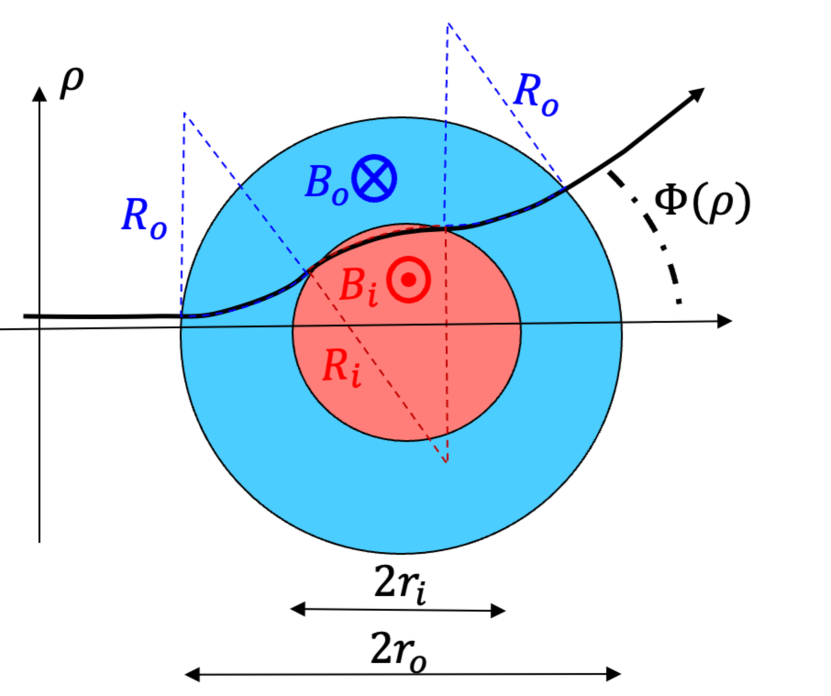
As a warm-up, we analyze classical scattering of electrons of the target skyrmion. We approximate the target-skyrmion as a two-shell structure shown in the Fig. 2. The inner (i) circular shell has a radius , and the outer (o) annular region has radius . The effective magnetic fields have opposite signs and , which we assume constant within the respective regions. The specific values are constrained by the condition that the total magnetic flux piercing through the structure vanishes, i.e.
| (7) |
In the presence of the effective magnetic fields and , the particles moves along the cyclotron trajectories with radii
| (8) |
determined by the magnetic fields in the respective regions and as well as the momentum . A representative electronic trajectory is shown in Fig. 2. By matching the circular trajectories in the two regions, we find the scattering angle dependence
| (9) | |||
on the impact parameter .
To get a feeling of Eq. (9), let us give the low-energy (high-field) limiting cases of
| (10) |
where only the first term in Eq. (9) corresponding to the outer skyrmion contributes, as well as the high-energy (low-field) limit
| (11) |
Here, the former and the latter terms represent the effect of the outer and inner skyrmions, respectively. The opposite sign of those terms correspond to the opposite direction of the Lorentz force acting in the respective regions. Then, it is instructive to evaluate the skew-scattering Hall (H) component of the differential cross-section (having units of length in 2D)
| (12) |
In the rest of the paper, we discuss the Hall resistance induced by a target skyrmion, so there is no confusion between the Hall conductivity and Eq. (12). Evaluating Eq. (12) for the low-energy (10) and the high-energy (11) limits, we obtain
| (13) | ||||
| (14) |
It is expected that at low energies, the carriers are deflected by the Lorentz force and are not able to penetrate into the inner shell of the target skyrmion. So the skew-scattering cross-section (13) is determined only by the effective magnetic field of the outer skyrmion. In the high-energy limit, it is interesting to note that vanishes once the constraint of equal magnetic fluxes (7) is taken into account. It corresponds to the known result in the literature [29], that skew-scattering is proportional to the magnetix flux at high energies. However, the latter vanishes for a target skyrmion. So, we expect a greater suppression of the Hall effect at higher energies relative to that of, e.g., conventional skyrmion generating nonzero magnetic flux. This consideration indicates that the Hall effect in a target skyrmion is a nonmonotonic function of both the carrier energy and target skyrmion radius. In the rest of the paper, we delve into that analysis for more realistic target skyrmion geometries.
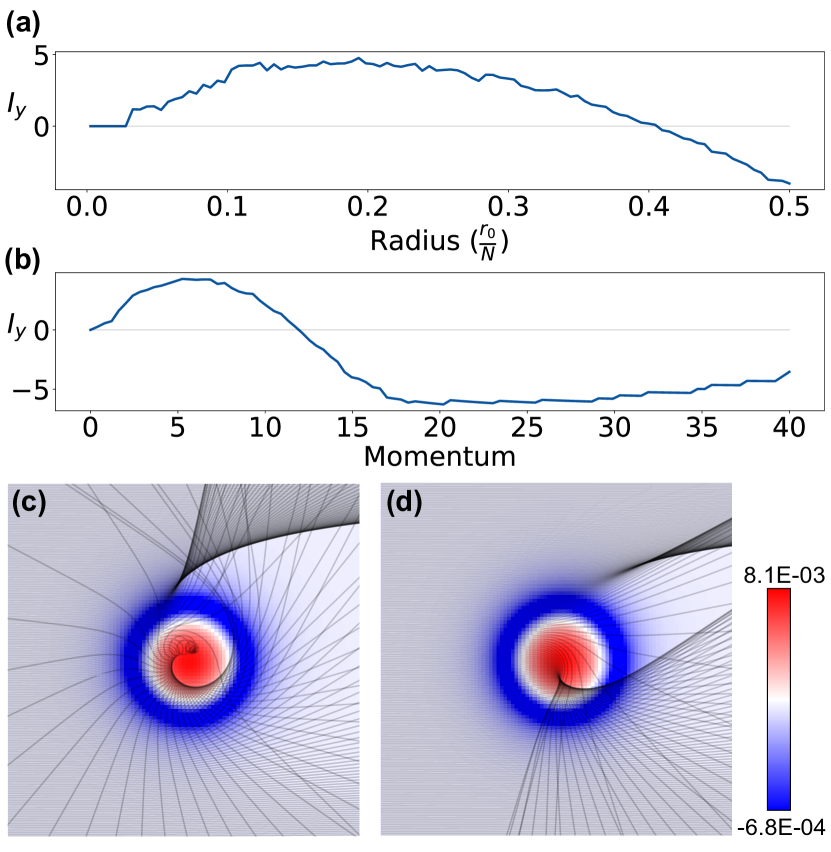
Next, we solve a continuous model of a target skyrmion profile illustrated in Fig. 3. We simulate a classical model of electrons traveling through a target skyrmion. Electrons obey Lorentz force , where there is no external electric field in our model. Using from Fig.1b, we calculate the transverse current . We used Runge-Kutta method to solve the differential equations of electrons in a magnetic field for . The initial condition for the simulation were an array of electrons uniformly distributed along the left lead with a fixed initial momentum in -direction. Here we set the electron charge and mass to one.
We calculated as a function of target skyrmion radius (Fig. 3a) and as a function of electron momentum (Fig. 3b). A sign switch in indicates a competing order between the inner and outer shell. The trajectories of the electrons traveling through the target skyrmion were plotted in Fig. 3c,d for and , respectively. For small momentum , is positive indicating that most of the electrons are deflected by the negative magnetic field of the outer shell. As shown in 3c where , the trajectories ended up in the top lead more than than bottom lead. For , we observed a sign switch of . Electrons with high momentum can pass through the outer shell with little change in their trajectories, but are strongly deflected to the bottom lead by the inner shell. In the high momentum limits, we see that approaches 0. Classically, we have shown that topological trivial target skyrmion can give raise to a non-monotonic behavior of the Hall effect due to variations in the magnetic field. The next section will focus on quantum transport of the target skrymion.
IV Numerical modeling.
IV.1 Tight binding model
Here we used Kwant, a software package for quantum transport, to calculate the Hall resistance and Hall angle of target skyrmion [30]. The tight-binding Hamiltonian of the conduction electron is given by,
| (15) |
where and are the fermionic creation and annihilation operators of an electron at site , is the nearest neighbor hopping, and is the Hund’s coupling strength between the itinerant electrons and the background spin texture . The band is symmetric with a band width of for . Above , the band is gapped with a gap of . Here we focus on , and the transport energy right below the edge of the band overlap region . In this range, we observed a non-monotonic behavior of the Hall effect as a function of the target skyrmion radius (Fig. 4a), where it is monotonic for the skyrmion in Ref. [28].
IV.2 Hall resistance and Hall angle
We simulate four ferromagnetic leads attached to the sample and calculate the transmission probabilities. The leads are fully attached to the left, right, top and bottom of the system. We impose current () from the left lead to the right lead and measure the voltage () across the top and bottom lead. We applied Landauer-Büttiker formalism to obtain the Hall resistance and Hall angle. The equation for Hall resistance is computed as [31],
| (16) |
where we set to unity. See appendix.A for leads configuration and derivation of the Hall resistance.
The Hall angle is defined as the resultant angle between the Hall voltage () and the longitudinal voltage (). Since contributed by the spin texture is very small compared to , the Hall angle thus can be expressed as the ratio between and (Eq 17). Where () is the difference between the top and bottom terminal voltages (left and right terminal voltages). Detailed derivations of the terminal voltages can be found in Ref. [28, 32].
| (17) |
V Results
V.1 Transport results for a target skyrmion
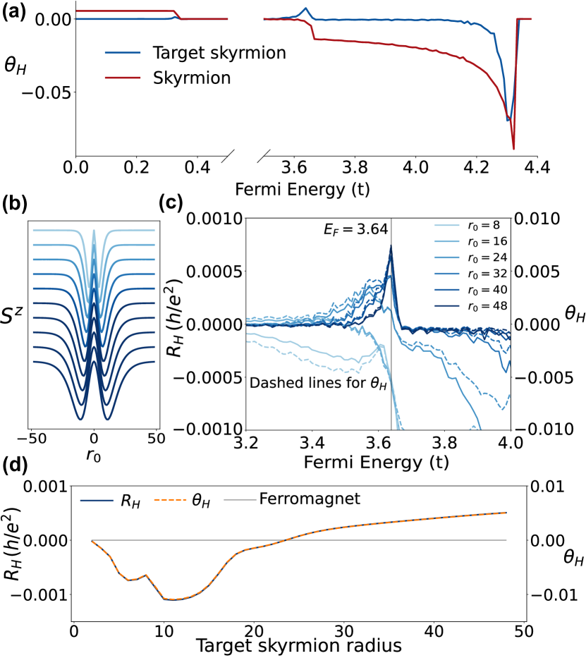
Here we start with a big picture by comparing the Hall angles between the normal skyrmion and the target skyrmion for . We calculated the Hall angle for system size x = 96x96 where is the lattice constant, and large initial to satisfy the adiabatic approximation for the skyrmion [28]. In the next section we show that also satisfies the adiabatic approximation for the target skyrmion. By sweeping the energy from to , we observed a zero Hall angle for in the target skyrmion, contrasting to a constant Hall angle for the skyrmion. For where the spin up and spin down electrons are mixed due to the band overlap, the skyrmion has a zero Hall angle, while the target skyrmion has a peak at the edge of the band overlap where . The zero Hall angle phenomena for the skyrmion has been thoroughly investigated in Ref.[28, 32].
We look closely at the peak at for the target skyrmion and study its radius dependence. Figure 4b shows along a line cut through the middle of the target skyrmion. As the radius increases, the target skyrmion transitions from a sharp spin texture to a slowly varying spins texture. Fig 4c shows the Hall angle and resistance for various radii. The peak disappears as the radius decreases. For small radius, , the Hall angle at full energy range is similar to the skyrmion. We fixed the transport energy at the peak position for and record the Hall angle and resistance.
Fig 4d shows a non-monotonic behavior of and . For , the system is in a perfect ferromagnetic state, therefore does not exhibit any Hall effects. For , and are negative. We also see a rough behavior for . This can be understood as when the inner shell is too small (i.e. its radius is less than 4), it can hardly be considered as a skyrmion. Therefore, the system as a whole is one large skyrmion with spin defects at the center, which explains the negative Hall effect in this region. As the radius increases, the inner shell starts to expand into a skyrmion. The outer and inner shell scatter electrons in opposite directions, and eventually they both cancel out for . For , and are positive, indicating that Hall effect is contributed by the inner shell. For comparison with a skyrmion, the Hall resistance and Hall angle become constant and independent of skyrmion’s radii for [28]. Here, we show that the Hall effect sign switches from negative to positive owing to the topological Hall effect of the outer and inner shell, respectively.
V.2 Adiabatic approximation: J dependence
To demonstrate that the results respect the adiabatic approximation, we show that the adiabatic parameter , where is defined as [10, 33]
| (18) |
where is the Fermi velocity electrons in the lead. is the electron precession frequency. is the characteristic length such that is rotated by an angle of . We calculated for various exchange coupling at the edge of the band overlap region to confirm that is greater than one.
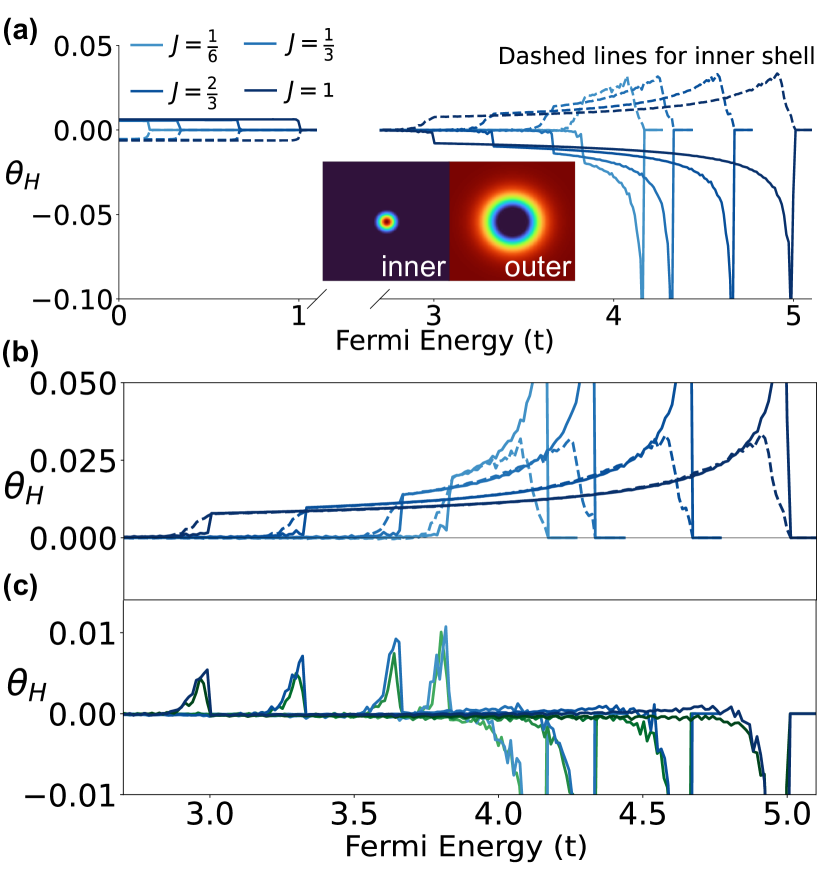
Without loss of generality, we focus only on the for the results presented in this section. We calculated the Hall angle of the target skyrmion for multiple with , and observed the magnitude of Hall angles decrease as increases (Fig. 5c). This may be seen as problematic as it indicates a vanishing Hall angle. Here we resolve this issue by demonstrating that the magnitude of the Hall angles are set by the finite Hall angle of a skyrmion in the adiabatic regime. To characterize dependence of the exchange coupling, we isolate the inner and outer shell of the target skyrmion and placed them in a ferromagnetic background with both having the same system size ().
We placed the inner shell in a spin down ferromagnet to prevent scattering from an abrupt domain wall. Similarly, we placed the outer shell in a spin up ferromagnetic background. Fig. 5a shows of the inner and outer shell, and the inset figures show of the inner and outer shell. Since the shells have opposite topological charge, their Hall angles also have the opposite signs: the inner shell has positive for , and the outer shell has negative . We zoom in on the energy range near the edge of the bands overlap and compare (Fig. 5b). We observed both shells have the same magnitude for . of the inner shell has a soft decrease to zero starting from , whereas the outer shell has an abrupt jump to zero. This difference gives raise to the Hall angle and the magnitude is set by the single skyrmion (Fig.5c). In the adiabatic limits, all skyrmion Hall angle becomes constant right above the band overlap region, and thus the target skyrmion’s Hall angle never vanishes for . We compared the total Hall angle obtained by calculating the contribution from each shells versus the calculation of one target skyrmion. Here we demonstrated that the Hall angle of the target skyrmion is the sum of the inner and outer shell’s Hall angles, as the Hall angles superimposed one another in Fig.5c. Furthermore, our results respect the adiabatic approximation which mean that the Hall angle arises from real space topology and can be classified as the topological Hall effect despite it the spin texture has trivial topology.
VI Conclusion
In this work, we investigated the Hall effect in a recently discovered target skyrmion spin configuration [22, 24, 25, 26, 27]. The target skyrmion is characterized by a zero skyrmion (topological) charge. We started from a highly-simplified semiclassical model of a target skyrmion and found that the Hall effect is a non-monotonic function of both the carrier energy and target skyrmion radius. On top of that, we found that the Hall effect changes sign, which indicates competition between opposite Hall effect produced by the inner and outer shell of the target skyrmion. This observation carries over to the fully quantum mechanical treatment, where we observed a nonmotonic Hall angle and Hall resistance as a function of starget skyrmion radius. We developed a method to better understand the transport contribution in the target skyrmion by isolating the shells in ferromagnetic backgrounds. We showed that, in the broad region of energies, the Hall effect can be decomposed into a superposition of the Hall effects produced by the distinct shells of the target skyrmion. This method could be applied to more complex spin textures, which may facilitate understanding of the result of transport theory calculations. Our results suggest that it may possible to detect the presence of target skyrmions in experiments and call for further experimental investigation of the Hall effect in such textures. Finally, our result challenges the popular belief in the community that the Hall effect necessarily implies a nonzero skyrmion number.
VII Acknowledgement
This work was supported by the U.S. Department of Energy, Basic Energy Science under award No. DE-SC0020221.
Appendix A Hall resistance
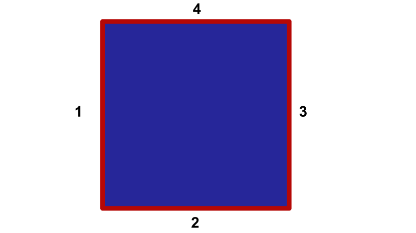
We ran a current from lead 1 to lead 3, and measure the voltage across lead 2 and 4. Without loss of generality we set and measure . Fig. 6 shows the leads configuration. We start with , where is the the conductance matrix defined as
| (19) |
Since four leads are completely symmetric, we can define forward transmission, right turning, and left turning as follows:
| (20) |
and
| (21) |
Solve for the voltage where is the resistance matrix (i.e. inverse of the conductance matrix). Using the current and , we obtained
References
- Hall et al. [1879] E. H. Hall et al., On a new action of the magnet on electric currents, Am. J. Math. 2, 287 (1879).
- Karplus and Luttinger [1954] R. Karplus and J. Luttinger, Hall effect in ferromagnetics, Phys. Rev. 95, 1154 (1954).
- Nagaosa et al. [2010] N. Nagaosa, J. Sinova, S. Onoda, A. H. MacDonald, and N. P. Ong, Anomalous Hall effect, Rev. Mod. Phys. 82, 1539 (2010).
- Taguchi et al. [2001] Y. Taguchi, Y. Oohara, H. Yoshizawa, N. Nagaosa, and Y. Tokura, Spin chirality, Berry phase, and anomalous Hall effect in a frustrated ferromagnet, Sci. 291, 2573 (2001).
- Fujishiro et al. [2021] Y. Fujishiro, N. Kanazawa, R. Kurihara, H. Ishizuka, T. Hori, F. S. Yasin, X. Yu, A. Tsukazaki, M. Ichikawa, M. Kawasaki, et al., Giant anomalous Hall effect from spin-chirality scattering in a chiral magnet, Nat. Commun. 12, 1 (2021).
- Ghimire et al. [2018] N. J. Ghimire, A. Botana, J. Jiang, J. Zhang, Y.-S. Chen, and J. Mitchell, Large anomalous Hall effect in the chiral-lattice antiferromagnet CoNb3S6, Nat. Commun. 9, 1 (2018).
- Yang et al. [2020] S.-Y. Yang, Y. Wang, B. R. Ortiz, D. Liu, J. Gayles, E. Derunova, R. Gonzalez-Hernandez, L. Šmejkal, Y. Chen, S. S. Parkin, et al., Giant, unconventional anomalous Hall effect in the metallic frustrated magnet candidate, KV3Sb5, Sci. Adv. 6, eabb6003 (2020).
- Ohuchi et al. [2018] Y. Ohuchi, J. Matsuno, N. Ogawa, Y. Kozuka, M. Uchida, Y. Tokura, and M. Kawasaki, Electric-field control of anomalous and topological Hall effects in oxide bilayer thin films, Nat. Commun. 9, 1 (2018).
- Xiao et al. [2010] D. Xiao, M.-C. Chang, and Q. Niu, Berry phase effects on electronic properties, Rev. Mod. Phys. 82, 1959 (2010).
- Bruno et al. [2004] P. Bruno, V. Dugaev, and M. Taillefumier, Topological Hall effect and Berry phase in magnetic nanostructures, Phys. Rev. Lett. 93, 096806 (2004).
- Do Yi et al. [2009] S. Do Yi, S. Onoda, N. Nagaosa, and J. H. Han, Skyrmions and anomalous Hall effect in a Dzyaloshinskii-Moriya spiral magnet, Phys. Rev. B 80, 054416 (2009).
- Hamamoto et al. [2015] K. Hamamoto, M. Ezawa, and N. Nagaosa, Quantized topological Hall effect in skyrmion crystal, Phys. Rev. B 92, 115417 (2015).
- Kurumaji et al. [2019] T. Kurumaji, T. Nakajima, M. Hirschberger, A. Kikkawa, Y. Yamasaki, H. Sagayama, H. Nakao, Y. Taguchi, T.-h. Arima, and Y. Tokura, Skyrmion lattice with a giant topological Hall effect in a frustrated triangular-lattice magnet, Sci. 365, 914 (2019).
- Neubauer et al. [2009] A. Neubauer, C. Pfleiderer, B. Binz, A. Rosch, R. Ritz, P. Niklowitz, and P. Böni, Topological Hall effect in the A phase of MnSi, Phys. Rev. Lett. 102, 186602 (2009).
- Gerber [2018] A. Gerber, Interpretation of experimental evidence of the topological Hall effect, Phys. Rev. B 98, 214440 (2018).
- Vistoli et al. [2019] L. Vistoli, W. Wang, A. Sander, Q. Zhu, B. Casals, R. Cichelero, A. Barthélémy, S. Fusil, G. Herranz, S. Valencia, et al., Giant topological Hall effect in correlated oxide thin films, Nat. Phys. 15, 67 (2019).
- Kanazawa et al. [2011] N. Kanazawa, Y. Onose, T. Arima, D. Okuyama, K. Ohoyama, S. Wakimoto, K. Kakurai, S. Ishiwata, and Y. Tokura, Large topological Hall effect in a short-period helimagnet MnGe, Phys. Rev. Lett. 106, 156603 (2011).
- Nagaosa and Tokura [2013] N. Nagaosa and Y. Tokura, Topological properties and dynamics of magnetic skyrmions, Nat. Nanotechnol. 8, 899 (2013).
- Finocchio et al. [2016] G. Finocchio, F. Büttner, R. Tomasello, M. Carpentieri, and M. Kläui, Magnetic skyrmions: from fundamental to applications, J. Phys. D: Appl. Phys. 49, 423001 (2016).
- Luo and You [2021] S. Luo and L. You, Skyrmion devices for memory and logic applications, APL Mater. 9, 050901 (2021).
- Fert et al. [2017] A. Fert, N. Reyren, and V. Cros, Magnetic skyrmions: advances in physics and potential applications, Nat. Rev. Mater. 2, 1 (2017).
- Tang et al. [2021] J. Tang, Y. Wu, W. Wang, L. Kong, B. Lv, W. Wei, J. Zang, M. Tian, and H. Du, Magnetic skyrmion bundles and their current-driven dynamics, Nat. Nanotechnol. 16, 1086 (2021).
- Zhang et al. [2016] X. Zhang, J. Xia, Y. Zhou, D. Wang, X. Liu, W. Zhao, and M. Ezawa, Control and manipulation of a magnetic skyrmionium in nanostructures, Phys. Rev. B 94, 094420 (2016).
- Kolesnikov et al. [2018] A. G. Kolesnikov, M. E. Stebliy, A. S. Samardak, and A. V. Ognev, Skyrmionium–high velocity without the skyrmion Hall effect, Sci. Rep. 8, 1 (2018).
- Zhang et al. [2018] S. Zhang, F. Kronast, G. van der Laan, and T. Hesjedal, Real-space observation of skyrmionium in a ferromagnet-magnetic topological insulator heterostructure, Nano Lett. 18, 1057 (2018).
- Shen et al. [2019] L. Shen, X. Li, Y. Zhao, J. Xia, G. Zhao, and Y. Zhou, Current-induced dynamics of the antiferromagnetic skyrmion and skyrmionium, Phys. Rev. Appl. 12, 064033 (2019).
- Seng et al. [2021] B. Seng, D. Schönke, J. Yeste, R. M. Reeve, N. Kerber, D. Lacour, J.-L. Bello, N. Bergeard, F. Kammerbauer, M. Bhukta, et al., Direct imaging of chiral domain walls and néel-type skyrmionium in ferrimagnetic alloys, Adv. Funct. Mater. 31, 2102307 (2021).
- Ndiaye et al. [2017] P. B. Ndiaye, C. A. Akosa, and A. Manchon, Topological hall and spin hall effects in disordered skyrmionic textures, Phys. Rev. B 95, 064426 (2017).
- Denisov et al. [2018] K. Denisov, I. Rozhansky, N. Averkiev, and E. Lähderanta, General theory of the topological Hall effect in systems with chiral spin textures, Phys. Rev. B 98, 195439 (2018).
- Groth et al. [2014] C. W. Groth, M. Wimmer, A. R. Akhmerov, and X. Waintal, Kwant: a software package for quantum transport, New J. Phys. 16, 063065 (2014).
- Datta [1997] S. Datta, Electronic transport in mesoscopic systems (Cambridge university press, 1997) Chap. 2 Conductance from transmission.
- Yin et al. [2015] G. Yin, Y. Liu, Y. Barlas, J. Zang, and R. K. Lake, Topological spin Hall effect resulting from magnetic skyrmions, Phys. Rev. B 92, 024411 (2015).
- Denisov [2020] K. Denisov, Theory of an electron asymmetric scattering on skyrmion textures in two-dimensional systems, J. Phys. Condens. Matter 32, 415302 (2020).