Non-Abelian braiding of graph vertices in a superconducting processor
Abstract
Indistinguishability of particles is a fundamental principle of quantum mechanics1. For all elementary and quasiparticles observed to date - including fermions, bosons, and Abelian anyons - this principle guarantees that the braiding of identical particles leaves the system unchanged2, 3. However, in two spatial dimensions, an intriguing possibility exists: braiding of non-Abelian anyons causes rotations in a space of topologically degenerate wavefunctions4, 5, 6, 7, 8. Hence, it can change the observables of the system without violating the principle of indistinguishability. Despite the well developed mathematical description of non-Abelian anyons and numerous theoretical proposals9, 10, 11, 12, 13, 14, 15, 16, 17, 18, 19, 20, 21, 22, the experimental observation of their exchange statistics has remained elusive for decades. Controllable many-body quantum states generated on quantum processors offer another path for exploring these fundamental phenomena. While efforts on conventional solid-state platforms typically involve Hamiltonian dynamics of quasi-particles, superconducting quantum processors allow for directly manipulating the many-body wavefunction via unitary gates. Building on predictions that stabilizer codes can host projective non-Abelian Ising anyons 9, 10, we implement a generalized stabilizer code and unitary protocol23 to create and braid them. This allows us to experimentally verify the fusion rules of the anyons and braid them to realize their statistics. We then study the prospect of employing the anyons for quantum computation and utilize braiding to create an entangled state of anyons encoding three logical qubits. Our work provides new insights about non-Abelian braiding and - through the future inclusion of error correction to achieve topological protection - could open a path toward fault-tolerant quantum computing.
Elementary particles in three dimensions (3D) are either bosons or fermions. The existence of only two types is rooted in the fact that the worldlines of two particles in 3+1 dimensions can always be untied in a trivial manner. Hence, exchanging a pair of indistinguishable particles twice is topologically equivalent to not exchanging them at all, and the wavefunction must remain the same. Representing the exchange as a matrix acting on the space of wavefunctions with a constant number of particles, it is thus required that (a scalar), leaving two possibilities: (bosons) and (fermions). Such continuous deformation is not possible in two dimensions (2D), thus allowing collective excitations (quasiparticles) to exhibit richer braiding behavior. In particular, this permits the existence of Abelian anyons2, 3, 24, 6, 7, 8, 25, where the global phase change due to braiding can take any value. It has been proposed that there exists another class of quasiparticles known as non-Abelian anyons, where braiding instead results in a change of the observables of the wavefunction4, 24, 5. In other words, does not simplify to a scalar, but remains a unitary matrix. Therefore, is a fundamental characteristic of anyon braiding. The topological approach to quantum computation26 aims to leverage these non-Abelian anyons and their topological nature to enable gate operations that are protected against local perturbations and decoherence errors27, 5, 28, 29, 30. In solid-state systems, primary candidates of non-Abelian quasiparticles are low-energy excitations in Hamiltonian systems, including the fractional quantum Hall states31, 32, vortices in topological superconductors33, 34, and Majorana zero modes in semiconductors proximitized by superconductors35, 36, 37, 38. However, direct verification of non-Abelian exchange statistics has remained elusive39, 40, 41.
We formulate the necessary requirements for experimentally certifying a physical system as a platform for topological quantum computation5, 26: (1) create an anyon pair; (2) verify the rules that govern the ”collision” of two anyons, known as the fusion rules; (3) verify the non-Abelian braiding statistics reflected in the matrix structure ; (4) realize controlled entanglement of anyonic degrees of freedom. Notably, the observation of steps (2-4) requires measurements of multi-anyon states, via fusion or non-local measurements.
The advent of quantum processors allows for controlled unitary evolution and direct access to the wavefunction rather than the parameters of the Hamiltonian. These features enable the use of local operations for efficient preparation of topological states that can host non-Abelian anyons, and - as we will demonstrate - their subsequent braiding and fusion. Moreover, these platforms allow for probing arbitrary Pauli strings through destructive multi-qubit (i.e. non-local) measurements. Since the braiding of non-Abelian anyons in this platform is achieved through unitary gate control rather than adiabatic evolution of a Hamiltonian system, we note that the anyons are not quasi-particles in the sense of eigenstates that persist throughout a Hamiltonian evolution. Importantly, their movement is achieved through local operations along their paths, and they are kept spatially separated throughout the braiding. We therefore emphasize that the 2D braiding processes are physically taking place on the device, leading to actual non-Abelian exchange effects of local anyons in the many-body wavefunction, rather than matrix operations that simply follow the same algebra.

In order to realize a many-body quantum state that can host anyons, it is essential to control the topological degeneracy. A suitable platform for achieving this requirement is a stabilizer code42, where the wavefunctions are characterized by a set of commuting operators called stabilizers, with and . The code space is the set of degenerate wavefunctions for which for all . Hence, every independent stabilizer divides the degeneracy of the code space by two.
While the physical layout of qubits is typically used to determine the structure of the stabilizers, the qubits can be considered to be degree- vertices (DV; ) on more general planar graphs (see Fig. 1a)23. Using this picture, each stabilizer can be associated with a plaquette , whose vertices are the qubits on which acts:
| (1) |
is here a single-qubit Pauli operator acting on vertex , chosen to satisfy a constraint around that vertex (Fig. 1b). An instance where on a plaquette is called a plaquette violation. These can be thought of as quasi-particles, which are created and moved through single-qubit Pauli operators (Fig. 1a). A pair of plaquette violations sharing an edge constitute a fermion, . We recently demonstrated the Abelian statistics of such quasiparticles in the surface code43. To realize non-Abelian statistics, one needs to go beyond such plaquette violations; it has been proposed that dislocations in the stabilizer graph - analogous to lattice defects in crystalline solids - can host projective non-Abelian Ising anyons9, 10. For brevity, we refer to these as ”non-Abelian anyons” or simply ”anyons” from here on.
In the graph framework introduced above, it has been shown that such dislocations are characterized as vertices of degree 2 and 3 (ref. 23). Consider the stabilizer graph of the surface code26, 44, specifically with boundary conditions such that the degeneracy is two. While all the vertices in the bulk are D4Vs, one can create two D3Vs by removing an edge between two neighboring plaquettes and , and introducing the new stabilizer (Fig. 1b). Evidently, the introduction of two D3Vs reduces the number of independent stabilizers by one and thus doubles the degeneracy. This doubling is exactly what is expected when a pair of Ising anyons is introduced9, 10; hence, D3Vs appear as a candidate of non-Abelian anyons, and we will denote them as .
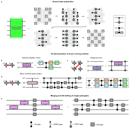
In order to be braided and fused by unitary operations, the D3Vs must be moved. While the structure of the stabilizer graph is usually considered to be static, it was predicted by Bombin that the dislocations in the surface code would exhibit projective non-Abelian Ising statistics if braided10. Here, we will employ a specific protocol recently proposed by Lensky et al.23 for deforming the stabilizer graph (and thus moving the anyons) using local two-qubit Clifford gates. To shift a D3V from vertex to , an edge must be disconnected from and reconnected to . This can be achieved via the gate unitary , where is the original stabilizer containing the edge and , and is the new stabilizer that emerges after moving the edge23. In cases where the D3V is shifted between two connected vertices, the unitary simplifies to the form , where and are Pauli operators acting on vertices and . We experimentally realize this unitary through a CZ-gate and single-qubit rotations (median errors of and , respectively; see Methods).

Following these insights from Kitaev and Bombin, we now turn to our experimental study of the proposed anyons, using the protocol described in Ref. 23. In the first experiment we demonstrate the creation of anyons and the fundamental fusion rules of and (Fig. 2a). In a 55 grid of superconducting qubits, we first use a protocol consisting of four layers of CZ-gates to prepare the surface code ground state (panel I in Fig. 2b, see also 43). The average stabilizer value after the ground state preparation is (individual stabilizer values shown in Extended Data Fig. 3c). We then remove a stabilizer edge to create a pair of D3Vs () and separate them through the application of two-qubit gates. Panels I-IV in Fig. 2b show the measured stabilizer values in the resultant graph in each step of this procedure (determined by simultaneously measuring the involved qubits in their respective bases, ; note that the measurements are destructive and the protocol is restarted after each measurement). In panel V, single-qubit -gates are applied to two qubits near the lower left corner of the grid to create adjacent plaquette violations, which together form a fermion. Through the sequential application of - and -gates (VI to VIII), one of the plaquette violations is then made to encircle the right vertex. Crucially, after moving around , the plaquette violation does not return to where it started, but rather to the location of the other plaquette violation. This enables them to annihilate (VIII), causing the fermion to seemingly disappear. However, by bringing the two back together and annihilating them (IX through XI), we arrive at a striking observation: an -particle re-emerges on two of the square plaquettes where the -vertices previously resided.
Our results demonstrate the fusion of and . The disappearance of the fermion from step V to VIII establishes the fundamental fusion rule of and :
| (2) |
We emphasize that none of the single-qubit gates along the path of the plaquette violation are applied to the qubits hosting the mobile ; our observations are therefore solely due to the non-local effects of non-Abelian D3Vs, and exemplify the unconventional behavior of the latter. Moreover, another fusion rule is seen by considering the reverse path IVI, and comparing it to the path VIIIXI. These two paths demonstrate that a pair of can fuse to form either vacuum () or one fermion (step I and XI, respectively):
| (3) |

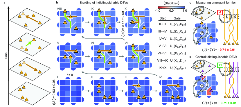
Importantly, the starting points of these two paths (IV and VIII) cannot be distinguished by any local measurement. We therefore introduce a non-local measurement technique that allows for detecting an without fusing the (Ref. 26, 10, 23). The key idea underlying this method is that bringing a plaquette violation around a fermion should result in a -phase. We therefore measure the Pauli string that corresponds to creating two plaquette violations, bringing one of them around the two , and finally annihilating them with each other (gray paths in Fig. 2c). The existence of an inside the -pair should cause . To simplify this technique further, can be reduced to a shorter string (black paths in Fig. 2c) by taking advantage of the stabilizers it encompasses. For instance, if contains three of the operators in a 4-qubit stabilizer, these can be switched out with the remaining operator. Measuring in step IV, where the are separated but the fermion has not yet been introduced, gives , consistent with the absence of fermions. However, performing the exact same measurement in step VIII, where the are in the same positions, we find , indicating that an is delocalized across the spatially separated -pair. This observation highlights the non-local encoding of the fermions, which cannot be explained with classical physics.

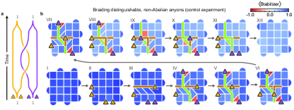
Having demonstrated the above fusion rules involving , we next braid them with each other to directly show their non-Abelian statistics. We consider two spatially separated -pairs, A and B, by removing two stabilizer edges (Fig. 3a and panel II in Fig. 3b). Next, we apply two-qubit gates along a horizontal path to separate the in pair A (panel III), followed by a similar procedure in the vertical direction on pair B (IV), so that one of its crosses the path of pair A. We then subsequently bring the from pairs A and B back to their original positions (V-VIII and IX-XI, respectively). Strikingly, when the two -pairs are annihilated in the final step (XII), we observe that a fermion is revealed in each of the positions where the -pairs resided (average stabilizer value: ). This shows a clear change in local observables from the initial state where no fermions were present. As a control experiment, we repeat the experiment with distinguishable -pairs, achieved by attaching a plaquette violation to each of the in pair B (Fig. 3c,d; see also Extended Data Fig. 8 for stabilizer measurements through the full protocol). Moving the plaquette violation along with the requires a string of single-qubit gates, which switches the direction of the rotation in the multi-qubit unitaries, . In this case, no fermions are observed at the end of the protocol (average stabilizer value: ), thus providing a successful control.
Importantly, fermions can only be created in pairs in the bulk. Moreover, the fusion of two can only create zero or one fermion (Eqn. 3). Hence, our experiment involves the minimal number of bulk (four) needed to encode two fermions and demonstrate non-Abelian braiding. Since the fermion parity is conserved, effects of gate imperfections and decoherence can be partially mitigated by post-selecting for an even number of fermions. This results in fermion detection values of and in Fig. 3b and d, respectively.
Together, our observations show the change in local observables by braiding of indistinguishable and constitute a direct demonstration of their non-Abelian statistics. In other words, the double-braiding operation is a matrix that cannot be reduced to a scalar. Specifically, it corresponds to an -gate acting on the space spanned by zero- and two-fermion wavefunctions.
The full braiding circuit consists of 40 layers of CZ-gates and 41 layers of single-qubit gates (36 of each after ground state preparation). The effects of imperfections in this hardware implementation can be assessed through comparison with the control experiment. The absolute values of the stabilizers where the fermions are detected in the two experiments (dashed boxes in step XII of Fig. 3b,d) are very similar (average values of and ). This is consistent with the depolarization channel model, where the measured stabilizer values are proportional to the ideal values ().
We next study the prospects of utilizing D3Vs to encode logical qubits and prepare an entangled state of anyon pairs. By doubling the degeneracy, each additional -pair introduces one logical qubit, where the () state corresponds to an even (odd) number of hidden fermions. Importantly, the measurements of the fermion numbers in several -pairs are not fully independent: bringing a plaquette violation around one -pair is equivalent to bringing it around all the other pairs (due to the conservation of fermionic parity). Hence, anyons encode logical qubits. Interestingly, the D3Vs we have created and manipulated so far are not the only ones present in the stabilizer graph; with the boundary conditions used here, each of the four corners are also D3Vs, no different from those in the bulk23. Indeed, the existence of D3Vs in the corners is the reason why a single fermion could be created in the corner in step V of Fig. 2b. This is also consistent with the fact that the surface code itself encodes one logical qubit in the absence of additional D3Vs. Here we create two pairs of D3Vs, in addition to the four that are already present in the corners, to encode a total of three logical qubits.
Through the use of braiding, we aim to prepare an entangled state of these logical qubits, specifically a GHZ-state on the form, . The definition of a GHZ-state and the specifics of how it is prepared is basis-dependent. In most systems the degrees of freedom are local and there is a natural choice of basis. For spatially separated anyons, the measurement operators are necessarily non-local. Here we choose the basis defined as follows: for the first two logical qubits, we choose the logical operators to be Pauli strings encircling each of the bulk -pairs, as was used in Fig. 2c (green and turquoise paths in the left column of Fig. 4a). For the logical surface code qubit, we define as the Pauli string that crosses the grid horizontally through the gap between the bulk D3V pairs, effectively enclosing four (red path in Fig. 4a). In this basis, the initial state is a product state.
While a double braid was used to implement the operator in Fig. 3, we now perform a single braid (Fig. 4b) to realize and create a GHZ-state. We implement this protocol by bringing one from each bulk pair across the grid to the other side (Fig. 4c). For every anyon double exchange across a Pauli string, the value of the Pauli string changes sign. Hence, a double exchange would change to , while a single exchange is expected to realize the superposition, .
In order to study the effect of this operation, we perform quantum state tomography on the final state, which requires measurements of not only , but also and on the three logical qubits. For the first two logical qubits, is the Pauli string that corresponds to bringing a plaquette violation around only one of the in the pair (as demonstrated in Fig. 2b). Both the logical and operators can be simplified by reducing the original Pauli strings (green and turquoise paths in the left column of Fig. 4c) to equivalent, shorter ones (right column). can in fact be reduced to a single -operator. For the logical surface code qubit, we define as the Pauli string that crosses the grid vertically between the bulk D3V pairs (red path in Fig. 4a). Finally, the logical -operators are simply found from . Measuring these operators, we reconstruct the density matrix of the final state (Fig. 4d,e), which has a purity of and an overlap with the ideal GHZ-state of (uncertainties estimated from bootstrapping method; resampled 10,000 times from the original data set). The fact that the state fidelity is similar to the purity suggests that the infidelity is well described by a depolarizing error channel.
In conclusion, we have realized highly controllable braiding of degree-3 vertices, enabling the demonstration of the fusion and braiding rules of non-Abelian Ising anyons. We have also shown that braiding can be used to create an entangled state of three logical qubits encoded in these anyons. In other, more conventional candidate platforms for non-Abelian exchange statistics, which involve Hamiltonian dynamics of quasi-particle excitations, topological protection naturally arises from an emergent gap that separates the computational states from other states. In order to leverage the non-Abelian anyons in our system for topologically protected quantum computing, the stabilizers must be measured throughout the braiding protocol. The potential inclusion of this error correction procedure, which involves overheads including readout of 5-qubit stabilizers, could open a new path toward fault-tolerant implementation of Clifford gates, a key ingredient of universal quantum computation.
Acknowledgments
YL and EAK acknowledge support by a New Frontier Grant from Cornell University’s College of Arts and Sciences. EAK acknowledges support by the NSF under OAC-2118310, the Ewha Frontier 10-10 Research Grant, and the Simons Fellowship in Theoretical Physics award 920665. EAK performed a part of this work at the Aspen Center for Physics, which is supported by the National Science Foundation grant PHY-160761.
† Google Quantum AI and Collaborators
T. I. Andersen1, Y. D. Lensky2, K. Kechedzhi1, I. K. Drozdov1, 3, A. Bengtsson1, S. Hong1, A. Morvan1, X. Mi1, A. Opremcak1, R. Acharya1, R. Allen1, M. Ansmann1, F. Arute1, K. Arya1, A. Asfaw1, J. Atalaya1, R. Babbush1, D. Bacon1, J. C. Bardin1, 4, G. Bortoli1, A. Bourassa1, J. Bovaird1, L. Brill1, M. Broughton1, B. B. Buckley1, D. A. Buell1, T. Burger1, B. Burkett1, N. Bushnell1, Z. Chen1, B. Chiaro1, D. Chik1, C. Chou1, J. Cogan1, R. Collins1, P. Conner1, W. Courtney1, A. L. Crook1, B. Curtin1, D. M. Debroy1, A. Del Toro Barba1, S. Demura1, A. Dunsworth1, D. Eppens1, C. Erickson1, L. Faoro1, E. Farhi1, R. Fatemi1, V. S. Ferreira1, L. F. Burgos1 E. Forati1, A. G. Fowler1, B. Foxen1, W. Giang1, C. Gidney1, D. Gilboa1, M. Giustina1, R. Gosula1, A. G. Dau1, J. A. Gross1, S. Habegger1, M. C. Hamilton1, 5, M. Hansen1, M. P. Harrigan1, S. D. Harrington1, P. Heu1, J. Hilton1, M. R. Hoffmann1, T. Huang1, A. Huff1, W. J. Huggins1, L. B. Ioffe1, S. V. Isakov1, J. Iveland1, E. Jeffrey1, Z. Jiang1, C. Jones1, P. Juhas1, D. Kafri1, T. Khattar1, M. Khezri1, M. Kieferová1, 6, S. Kim1, A. Kitaev1, P. V. Klimov1, A. R. Klots1, A. N. Korotkov1, 7, F. Kostritsa1, J. M. Kreikebaum1, D. Landhuis1, P. Laptev1, K.-M. Lau1, L. Laws1, J. Lee1, 8, K. W. Lee1, B. J. Lester1, A. T. Lill1, W. Liu1, A. Locharla1, E. Lucero1, F. D. Malone1, O. Martin1, J. R. McClean1, T. McCourt1, M. McEwen1, 9, K. C. Miao1, A. Mieszala1, M. Mohseni1, S. Montazeri1, E. Mount1, R. Movassagh1, W. Mruczkiewicz1, O. Naaman1, M. Neeley1, C. Neill1, A. Nersisyan1, M. Newman1, J. H. Ng1, A. Nguyen1, M. Nguyen1, M. Y. Niu1, T. E. O’Brien1, S. Omonije1, A. Petukhov1, R. Potter1, L. P. Pryadko1,10, C. Quintana1, C. Rocque1, N. C. Rubin1, N. Saei1, D. Sank1, K. Sankaragomathi1, K. J. Satzinger1, H. F. Schurkus1, C. Schuster1, M. J. Shearn1, A. Shorter1, N. Shutty1, V. Shvarts1, J. Skruzny1, W. C. Smith1, R. Somma1, G. Sterling1, D. Strain1, M. Szalay1, A. Torres1, G. Vidal1, B. Villalonga1, C. V. Heidweiller1, T. White1, B. W. K. Woo1, C. Xing1, Z. J. Yao1, P. Yeh1, J. Yoo1, G. Young1, A. Zalcman1, Y. Zhang1, N. Zhu1, N. Zobrist1, H. Neven1, S. Boixo1, A. Megrant1, J. Kelly1, Y. Chen1, V. Smelyanskiy1, E.-A. Kim, I. Aleiner, P. Roushan,
1 Google Research, Mountain View, CA, USA
2 Department of Physics, Cornell University, Ithaca, NY, USA
3 Department of Physics, University of Connecticut, Storrs, CT, USA
4 Department of Electrical and Computer Engineering, University of Massachusetts, Amherst, MA, USA
5 Department of Electrical and Computer Engineering, Auburn University, Auburn, AL, USA
6 QSI, Faculty of Engineering & Information Technology, University of Technology Sydney, NSW, Australia
7 Department of Electrical and Computer Engineering, University of California, Riverside, CA, USA
8 Department of Chemistry, Columbia University, New York, NY, USA
9 Department of Physics, University of California, Santa Barbara, CA, USA
10 Department of Physics and Astronomy, University of California, Riverside, CA, USA
11 Department of Physics, Ewha Womans University, Seoul, South Korea
12 Department of Physics, Harvard University, Cambridge, MA, USA
13 Radcliffe Institute for Advanced Studies, Cambridge, MA, USA
§ Corresponding author: ek436@cornell.edu
§ Corresponding author: igoraleiner@google.com
§ Corresponding author: pedramr@google.com
References
- [1] Sakurai, J. J. Modern Quantum Mechanics (Addison-Wesley, 1993).
- [2] Leinaas, J. & Myrheim, J. On the theory of identical particles. Nuovo Cim B 37, 1–23 (1977).
- [3] Wilczek, F. Quantum mechanics of fractional-spin particles. Phys. Rev. Lett. 49, 957–959 (1982).
- [4] Wilczek, F. Fractional statistics and anyon superconductivity (World Scientific, 1990).
- [5] Nayak, C., Simon, S. H., Stern, A., Freedman, M. & Sarma, S. D. Non-Abelian Anyons and Topological Quantum Computation. Rev. Mod. Phys. 80, 1083–1159 (2008).
- [6] Camino, F. E., Zhou, W. & Goldman, V. J. laughlin quasiparticle primary-filling interferometer. Phys. Rev. Lett. 98, 076805 (2007).
- [7] Bartolomei, H. et al. Fractional statistics in anyon collisions. Science 368, 173–177 (2020).
- [8] Nakamura, J., Liang, S., Gardner, G. C. & Manfra, M. J. Direct observation of anyonic braiding statistics. Nature Physics 16, 931––936 (2020).
- [9] Kitaev, A. Anyons in an exactly solved model and beyond. Ann. Phys. 321, 2–111 (2006).
- [10] Bombin, H. Topological order with a twist: Ising anyons from an abelian model. Phys. Rev. Lett. 105, 030403 (2010).
- [11] Hormozi, L., Zikos, G., Bonesteel, N. E. & Simon, S. H. Topological quantum compiling. Phys. Rev. B 75, 165310 (2007).
- [12] You, Y.-Z. & Wen, X.-G. Projective non-abelian statistics of dislocation defects in a rotor model. Phys. Rev. B 86, 161107 (2012).
- [13] Barkeshli, M., Jian, C.-M. & Qi, X.-L. Twist defects and projective non-abelian braiding statistics. Phys. Rev. B 87, 045130 (2013).
- [14] Barkeshli, M. & Qi, X.-L. Topological nematic states and non-abelian lattice dislocations. Phys. Rev. X 2, 031013 (2012).
- [15] von Keyserlingk, C. W., Burnell, F. J. & Simon, S. H. Three-dimensional topological lattice models with surface anyons. Phys. Rev. B 87, 045107 (2013).
- [16] Teo, J. C., Roy, A. & Chen, X. Unconventional fusion and braiding of topological defects in a lattice model. Phys. Rev. B 90, 115118 (2014).
- [17] Zheng, H., Dua, A. & Jiang, L. Demonstrating non-abelian statistics of majorana fermions using twist defects. Phys. Rev. B 92, 245139 (2015).
- [18] Teo, J. C., Hughes, T. L. & Fradkin, E. Theory of twist liquids: Gauging an anyonic symmetry. Ann. Phys. 360, 349–445 (2015).
- [19] Brown, B. J., Laubscher, K., Kesselring, M. S. & Wootton, J. R. Poking holes and cutting corners to achieve clifford gates with the surface code. Phys. Rev. X 7, 021029 (2017).
- [20] Zhu, G., Hafezi, M. & Barkeshli, M. Quantum origami: Transversal gates for quantum computation and measurement of topological order. Phys. Rev. Research 2, 013285 (2020).
- [21] Benhemou, A., Pachos, J. K. & Browne, D. E. Non-abelian statistics with mixed-boundary punctures on the toric code. Phys. Rev. A 105, 042417 (2022).
- [22] Tantivasadakarn, N., Verresen, R. & Vishwanath, A. The Shortest Route to Non-Abelian Topological Order on a Quantum Processor. Pre-print at https://arxiv.org/abs/2209.03964 (2022).
- [23] Lensky, Y. D., Kechedzhi, K., Aleiner, I. & Kim, E.-A. Graph gauge theory of mobile non-abelian anyons in a qubit stabilizer code. Pre-print at https://arxiv.org/abs/2210.09282 (2022).
- [24] Stern, A. Anyons and the quantum hall effect-a pedagogical review. Ann. Phys. 323 (2008).
- [25] Harle, N., Shtanko, O. & Movassagh, R. Observing and braiding topological Majorana modes on programmable quantum simulators. Pre-print at https://arxiv.org/abs/2203.15083 (2022).
- [26] Kitaev, A. Y. Fault-tolerant quantum computation by anyons. Ann. Phys. 303, 2–30 (2003).
- [27] Freedman, M. H. P/np, and the quantum field computer. Proc. Natl. Acad. Sci. U.S.A. 95, 98–101 (1998).
- [28] Pachos, J. K. Introduction to Topological Quantum Computation (Cambridge University Press, 2012).
- [29] Stern, A. & Lindner, N. Topological quantum computation—from basic concepts to first experiments. Science 339, 1179–1184 (2013).
- [30] Field, B. & Simula, T. Introduction to topological quantum computation with non-abelian anyons. Quantum Science and Technology 3, 045004 (2018).
- [31] Moore, G. & Read, N. Nonabelions in the fractional quantum hall effect. Nuclear Physics B 360, 362–396 (1991).
- [32] Willett, R. L., Pfeiffer, L. N. & West, K. W. Alternation and interchange of e/4 and e/2 period interference oscillations consistent with filling factor 5/2 non-abelian quasiparticles. Phys. Rev. B 82, 205301 (2010).
- [33] Read, N. & Green, D. Paired states of fermions in two dimensions with breaking of parity and time-reversal symmetries and the fractional quantum hall effect. Phys. Rev. B 61, 10267 (2000).
- [34] Ivanov, D. A. Non-abelian statistics of half-quantum vortices in -wave superconductors. Phys. Rev. Lett. 86, 268–271 (2001).
- [35] Lutchyn, R. M., Sau, J. D. & Das Sarma, S. Majorana fermions and a topological phase transition in semiconductor-superconductor heterostructures. Phys. Rev. Lett. 105, 077001 (2010).
- [36] Oreg, Y., Refael, G. & von Oppen, F. Helical liquids and majorana bound states in quantum wires. Phys. Rev. Lett. 105, 177002 (2010).
- [37] Mourik, V. et al. Signatures of majorana fermions in hybrid superconductor-semiconductor nanowire devices. Science 336, 1003–1007 (2012).
- [38] Nadj-Perge, S. et al. Observation of majorana fermions in ferromagnetic atomic chains on a superconductor. Science 346, 602–607 (2014).
- [39] Banerjee, M. et al. Observation of half-integer thermal hall conductance. Nature 559, 205––210 (2018).
- [40] Kasahara, Y. et al. Majorana quantization and half-integer thermal quantum hall effect in a Kitaev spin liquid. Nature 559, 227––231 (2018).
- [41] Bonderson, P., Kitaev, A. & Shtengel, K. Detecting Non-Abelian Statistics in the Fractional Quantum Hall State. Phys. Rev. Lett. 96, 016803 (2006).
- [42] Gottesman, D. Stabilizer codes and quantum error correction (California Institute of Technology, 1997).
- [43] Satzinger, K. et al. Realizing topologically ordered states on a quantum processor. Science 374, 1237–1241 (2021).
- [44] Wen, X.-G. Quantum orders in an exact soluble model. Phys. Rev. Lett. 90, 016803 (2003).
Methods
.1 Qubit decoherence and gate characterization
The experiments are performed on a quantum processor with frequency-tunable transmon qubits and a similar design to that in Ref. 1. Extended Data Figure 1a shows the measured relaxation times of the 25 qubits that were used in the experiment, with a median value of s. We also measure the dephasing time in a Hahn echo experiment, shown in Extended Data Fig. 1b, with the same median value of 21.7 s. We note that the equality of T1 and T2 is a coincidence and that the discrepancy between the measured decoherence rate and the relaxation-limited rate is due to remnant noise not decoupled in the Hahn echo experiment.
Next, we benchmark the gates used in the experiment. Extended Data Fig. 2a and b show the cummulative distribution of the Pauli errors for single- and two-qubit (CZ) gates, respectively. The median Pauli errors are for the single-qubit gates and for the two-qubit gates.


.2 Readout details
Since the readout of the qubit state is imperfect, the raw data gives a somewhat incorrect representation of the actual quantum state of the system. We write the probability of readout error of state 0(1) on qubit as , and the readout fidelity is thus given by . In order to correct for any asymmetry between readout of the and states, we perform symmetrized measurements in which -pulses are applied to the qubits before the readout in half of the measurements and the recorded qubit values are inverted. The measured value of a stabilizer with actual value (where the product runs over qubits in the stabilizer) is then:
| (1) |
where we made use of the fact that each qubit is measured equally often in the and states in the symmetrized measurements. Note the absence of the factor compared to the expression for the readout fidelity, since perfectly incorrect readout () would give a readout fidelity of 0, but a measured value of . In order to correct for the discrepancy between the measured stabilizer value and the actual stabilizer value, we measure of the state with the same qubits (using again symmetrized measurements) to find:
| (2) |
The readout-corrected is then found from:
| (3) |
Extended Data Fig. 3 displays the measured readout errors, as well as a comparison of the stabilizer values in the surface code ground state (same data as in step I in main text Fig. 2) before and after readout correction.

.3 Dynamical decoupling
In order to mitigate the effects of qubit decoherence during the circuits, we perform dynamical decoupling on qubits that are idle for more than three layers of gates. In particular, we utilize the Carr-Purcell-Meiboom-Gill (CPMG) scheme, consisting of -pulses interspaced by a wait time of ns. Extended Data Fig. 4 shows an example comparison of the stabilizers in cases with and without dynamical decoupling, after braiding of anyons (41 layers of SQ gates and 40 layers of CZ-gates). A clear improvement is observed, increasing the average absolute stabilizer value from 0.50 to 0.58.

.4 Circuit details
Extended Data Fig. 5 shows the circuits used in the experiments presented in the main text. In our experiment, the two-qubit unitaries are converted to single-qubit rotations and CZ-gates, as shown in Extended Data Fig. 6b. In the particular case where a D3V is moved diagonally (see step IV in Fig. 3 in the main text), we realize the unitary by including two SWAP-gates (also converted to CZ-gates) since the qubits are connected in a square grid (see Extended Data Fig. 6c). Moreover, the three-qubit unitary in step VIII in Fig. 3 is equivalent to a combination of single-qubit gates, 4 SWAP-gates and 4 CZ-gates (Extended Data Fig. 6d), which can be further converted to single-qubit gates and 15 CZ-gates. In the experimental implementation of the circuit, adjacent single-qubit gates on the same qubit are merged together and performed in the layer after the most recent CZ-gate (Extended Data Fig. 6e).

.5 Numerical simulation of braiding in presence of noise
To better understand the role of errors in the experimental results in Fig. 3 of the main text, we perform a numerical simulation of the density matrix evolution subject to the braiding circuit in the presence of noise. We use the method of quantum trajectories to approximate the expectation value of stabilizers with the 25-qubit density matrix. The model of noise includes and effects described by the single qubit Kraus operators,
| (6) | |||
| (9) | |||
| (12) |
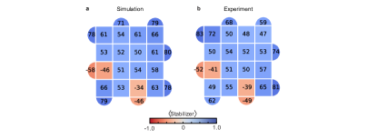
where is the duration of the evolution, as well as additional one- and two- qubit depolarizing channel error for each gate. The depolarizing channel error rate is chosen such that the combined Pauli error from , and depolarizing error matches the gate Pauli error measured in an independent experiment, see Section. A. We take these values to be uniform across the chip. The expectation values of the four stabilizers that correspond to the noise-free value of -1, see light red stabilizers in Fig. 3b (panel XII) and Extended Data Fig. 7, have the following values (): with statistical error . For comparison, the experimental values for the same set of stabilizers is . Our simulation results are in relatively good agreement with the measured data, suggesting that the model captures the effects of noise well. The observed discrepancies are expected to be due to inhomogeneity of the errors, which was not included in our error model. The simulations used an open source simulator qsim 2.
.6 Additional braiding data
In Figure 3 in the main text, we demonstrate that no fermion appears when distinguishable are braided with each other. In Extended Data Fig. 8, we show the data for each step in that protocol, analogous to those shown for indistinguishable in the main text. Moreover, we also present an alternative braiding scheme in Extended Data Fig. 9, which requires fewer (18) CZ-gates. In this case, however, pair B is not brought back together, and neither of the -pairs are annihilated. Therefore, similar to in Fig. 2c, we measure the Pauli string corresponding to bringing a plaquette violation around pair A (gray path in Extended Data Fig. 9c), which in this case can be reduced to on the qubit where the two overlap. We find , indicating that braiding the led to the creation of a fermion (Extended Data Fig. 9c). Note that we here only search for fermions in one of the -pairs. As a control experiment, we repeat the experiment with distinguishable -pairs, as in the main text (Extended Data Fig. 9d). In this case, we find , thus demonstrating that no fermion was produced. Together, these observations constitute another demonstration of non-Abelian exchange statistics of the D3Vs.
.7 A summary of the theoretical framework
It was observed by Kitaev that fluxes of the e-m exchange symmetry are expected to host Majorana modes and therefore have the degeneracy of Ising anyons 9. Bombin gave a particular stabilizer configuration realizing such a flux as a fixed lattice dislocation in a square grid, showed on general grounds that if such fluxes were well-separated and could be braided they would be projective Ising anyons, and noted that it may be possible to braid such fluxes by code deformation 10. A general formalism for theories realized by braiding of symmetry fluxes was described in Ref. 3. These constructions focus on the long-distance physics, and in practical terms 23 gives an account of ”microscopics”. An explicit mapping to a gauge theory shows how the anyons are localized to a single qubit, and is used to derive a simple, efficient, and systematic procedure for creating, braiding, and measuring the fusion outcomes of Ising anyons on general stabilizer graphs. The bridge between the microscopics and general arguments established by the gauge theory mapping allows us to fit several anyons on present-day devices, probe the full 2-dimensional nature of their braiding by maintaining their separation, and demonstrate braid generators which restore all local observables. For details discussions of the protocol see Ref. 23.
References
- [1] Arute, F. et al. Quantum supremacy using a programmable superconducting processor. Nature 574, 505–510 (2019).
- [2] Isakov, S. V. et al. Simulations of quantum circuits with approximate noise using qsim and cirq. Pre-print at https://arxiv.org/abs/2111.02396 (2021).
- [3] Barkeshli, M., Bonderson, P., Cheng, M. & Wang, Z. Symmetry fractionalization, defects, and gauging of topological phases. Phys. Rev. B 100, 115147 (2019).