Edge-based Monocular Thermal-Inertial Odometry in Visually Degraded Environments
Abstract
State estimation in complex illumination environments based on conventional visual-inertial odometry is a challenging task due to the severe visual degradation of the visual camera. The thermal infrared camera is capable of all-day time and is less affected by illumination variation. However, most existing visual data association algorithms are incompatible because the thermal infrared data contains large noise and low contrast. Motivated by the phenomenon that thermal radiation varies most significantly at the edges of objects, the study proposes an ETIO, which is the first edge-based monocular thermal-inertial odometry for robust localization in visually degraded environments. Instead of the raw image, we utilize the binarized image from edge extraction for pose estimation to overcome the poor thermal infrared image quality. Then, an adaptive feature tracking strategy ADT-KLT is developed for robust data association based on limited edge information and its distance distribution. Finally, a pose graph optimization performs real-time estimation over a sliding window of recent states by combining IMU pre-integration with reprojection error of all edge feature observations. We evaluated the performance of the proposed system on public datasets and real-world experiments and compared it against state-of-the-art methods. The proposed ETIO was verified with the ability to enable accurate and robust localization all-day time.
Index Terms:
Thermal-Inertial Odometry, Edge information, Visual Degradation.I INTRODUCTION
Accurate and robust state estimation in GNSS-denied environments is an active research field due to its wide applications in simultaneous localization and mapping (SLAM), 3D reconstruction, and active exploration. The sensor suit consisting of a monocular camera and IMU, which provides complementary information, is the minimum solution for recovering the metric six degrees-of-freedom (DOF)[1]. Considering that both camera and IMU are light-weight and low-cost, monocular visual-inertial odometry (VIO) is a common solution for localization and navigation[2]. Existing VIO frameworks have been mature in stable environments. However, the environments in disaster areas are uncertain and prone to extreme light distribution, dynamic illumination variation, or visual obscurants such as dust, fog, and smoke[3]. Such visual degradation always reduces the reliability of VIO estimation solutions.
Thermal infrared camera, operating in the longwave infrared spectrum and capturing thermal-radiometric information, has attracted more attention in recent years. Compared with the visual camera, thermal infrared cameras exhibit evident advantages when applied to disaster areas for their all-day perceptual capability[4]. However, using thermal infrared cameras directly to existing VIO frameworks is challenging for the following reasons. First, the captured image data are typically low contrast[5]. Second, many vision-observable information-rich textures, such as colors and streaks, are lost in thermal images due to the indistinguishability of thermal radiation from surrounding regions. Lastly, nonuniformity correction (NUC) or flat‐field correction (FFC) is performed during thermal infrared camera operation to eliminate accumulated nonzero‐mean noise[6]. Such blackout not only introduces periods of data interruption but may also significantly change image appearance between consecutive frames.
The current thermal-inertial odometry (TIO) solutions are mainly improved from normal VIO. Feature-based thermal odometry that requires special contrast enhancement on infrared images for feature extraction was developed [7, 8, 9]. However, preprocessing will induce additional noise, resulting in wrong correspondences. 14-bit or 16-bit full radiometric data from a thermal infrared camera was directly utilized for motion estimation [10, 3] to avoid a significant change in image appearance resulting from rescaling operation. However, their approaches require enabling NUC in long-term applications to address the temperature drift problem and are not directly compatible with the 8-bit image. By selecting the most reliable modality through several metrics, ROVTIO[11] fuses asynchronous thermal, visual and inertial measurements for estimating the odometry, which leads the system to autonomous switch between the different modalities according to the environmental conditions.
With the development of deep learning, the neural network is introduced into pose estimation from thermal infrared images. TP-TIO[12], which utilizes CNN for feature detection and IMU-aided full radiometric-based KLT method for feature tracking, is the first tightly coupled deep thermal-inertial odometry algorithm. Combining the hallucination network with a selective fusion mechanism, Saputra .[13] proposed a deep neural odometry architecture for pose regression named DeepTIO, which introduced an end-to-end scheme. Based on DeepTIO, Saputra .[14] recently presented a complete thermal-inertial SLAM system, including neural abstraction, graph-based optimization, and a global descriptor-based neural loop closure detection. Combining the advantage of conventional and learning-based methods, Jiang .[15] proposed a real-time system with an image enhancement method for feature detection and a light-weight optical flow network for feature tracking.
The learning-based approach presents promising results. However, it needs GPU for algorithm acceleration and is unsuitable for low-cost and low-load applications. In addition, the transferability of network models hinders the popularization of learning-based methods. Considering the ground robots or MAVs in rescue applications, this study follows the conventional framework for real-time state estimation with CPU-only, and the robustness of data association is the core problem to be addressed.
Most existing VIO systems generally use the point features as the visual information. However, point features detection and tracking in textureless or varying illumination environments are challenging[16]. Systems integrating additional geometry structure constraints, such as line and plane information, were proposed to supplement the point features and improve the robustness of state estimation[17, 18, 19]. Edge provides semi-dense information about the environment’s structure and exhibits a crossover between indirect and direct methodologies[20]. Literature [21, 22] developed real-time edge-based visual odometry (REBVO) for indoor localization, in which edge matching is directly performed via edge contour alignment by minimizing distance transform (DT) error. Based on a local sliding window optimization over several keyframes, Fabian Schenk .[23] presented the first edge-based SLAM system. By formulating the ICP-based motion estimation as maximum a posteriori (MAP) estimation, Zhou .[24] tracked edge features based on the approximate nearest neighbor fields.
Inspired by the significant change in thermal radiation at the edge of objects, our previous work developed an edge-based infrared visual odometry that detects and tracks the reliable edges in images to address the limitations of thermal infrared images in data association[20]. As a matter of course, this study presents an edge-based monocular thermal-inertial odometry (ETIO) that uses the edge information in the front‐end component to establish reliable correspondences between images. And in the back-end component, a pose graph optimization performs estimation over a sliding window of recent states by combining IMU pre-integration factors with reprojection error of all edge feature observations. Such an optimization scheme can effectively suppress the influence of data interruption on state estimation. The main contributions of this letter are three-fold:
-
1.
An edge-based thermal-inertial odometry, named ETIO, is proposed to provide real-time state estimation in visually degraded environments. To the best of our knowledge, it is the first edge-based TIO and outperforms state-of-the-art TIO methods.
-
2.
An adaptive distance transform-aided KLT (ADT-KLT) tracker is proposed based on limited edge information and distance field to improve the feature tracking robustness.
-
3.
Experiments in public datasets and the real-world show our method achieves competitive accuracy and robustness in all-day state estimation.
II SYSTEM OVERVIEW
Our algorithm is specifically designed for the thermal infrared camera. The overall framework of the proposed ETIO consists of three major modules shown in Figure1. The system starts with an image preprocessing module. Thermal infrared images even with poor quality are converted to binarized edge images by the Difference of Gaussians (DoG) and sub-pixel refinement. As a feature enhancement algorithm, the DoG can be utilized to increase the visibility of edges and filter out the low-contrast areas. Further, sub-pixel refinement is also utilized for edge thining.

In the data association module, the distance field of the edge image is utilized to introduce spatial distribution constraints and a stability analysis is performed to assess the consistency of distance field with the help of IMU pre-integration[25]. With an adaptive switching policy, the ADT-KLT tracker is developed for robust feature tracking on edge images. Finally, a sliding-window optimization module is developed to tightly and efficiently fuse the measurement information from point features and IMU pre-integration.
Frame and notation definitions used throughout this paper is defined as follows. We consider as the camera frame, as the body frame located at the IMU frame, and as the world frame. The world frame is consistent with at the initial position. reflects the coordinate transformation from th body frame to the world frame. To formulate the TIO optimization problem with a commonly-used sliding window[1], we first define the IMU state at time as
| (1) |
with the position , orientation , velocity and biases of the accelerometer and gyroscope and , respectively.
Together with the point features parameterized by the inverse depth , the full state vector to be estimated is defined as follows
| (2) |
with a sliding window of states and edge point features.
III METHODOLOGY
This section presents the details of ETIO shown in Figure1. Firstly, the salient edge points for each new thermal infrared image frame are extracted to filter the noisy or low-contrast areas. Then, the existing features are tracked, and new features are detected to maintain a minimum number of features. An ADT-KLT tracker based on Distance Transform is presented for robust data association on sparse edge images. Finally, a sliding window-based tightly coupled framework is utilized for high accuracy and efficient state estimation.
III-A Edge Extraction
Robustness and repeatability of edge extraction in consecutive frames are essential to implement robust feature associations. The accuracy of the 2D edges in the thermal infrared image frame is also an important factor for state estimation accuracy. In this study, the DoG edge detector [26] is applied to filter noise and low contrast area given as
| (3) |
where the represents the image convoluted to the difference of two Gaussian blur with kernel and , . It can not only enhance edge visibility but also repress image noise. The gradient of the image is also calculated in the filtered image by using a small sigma Gaussian filter, and then the wrong edges derived from image noises and low contrast areas are eliminated by thresholding the gradient magnitude.
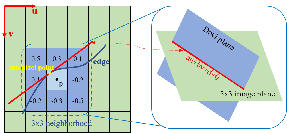
To achieve better extraction accuracy, a 3D plane that fits the DoG values within a neighborhood of 3x3 pixels is expressed as
| (4) |
where is the 2D image coordinates, and is the corresponding DoG value. As shown in Figure2, the sub-pixel edge point is the vertical projection point of the edge’s center on the DoG zero-crossing line. Edge gradient is obtained through the equation coefficients . If an edge point’s sub-pixel is located more than half a pixel away from the edge point’s center, the edge point is eliminated. Based on the DoG-based edge extraction, the pixels in an edge are connected by searching the points within eight neighborhoods. Finally, we obtain the accurate position of each edge point.
III-B Distance Transform-aided KLT Feature Tracking
Edge association of edge images is more challenging than normal images. Descriptors with enough discrimination cannot be extracted from the sparse binarization image, which causes the known descriptor-based matching[27] infeasible. The standard KLT tracker[1] uses spatial intensity information to establish point correspondences based on the brightness constancy assumption. But for edge images, the content of image patches is binarized and always sparse. Such degradation may cause the KLT tracker to fall into local optima, resulting in feature tracking errors. Therefore, this paper presents a new KLT-based tracker to deal with the lack of photometric information in edge images by introducing the Distance Transform called DT-KLT tracker.
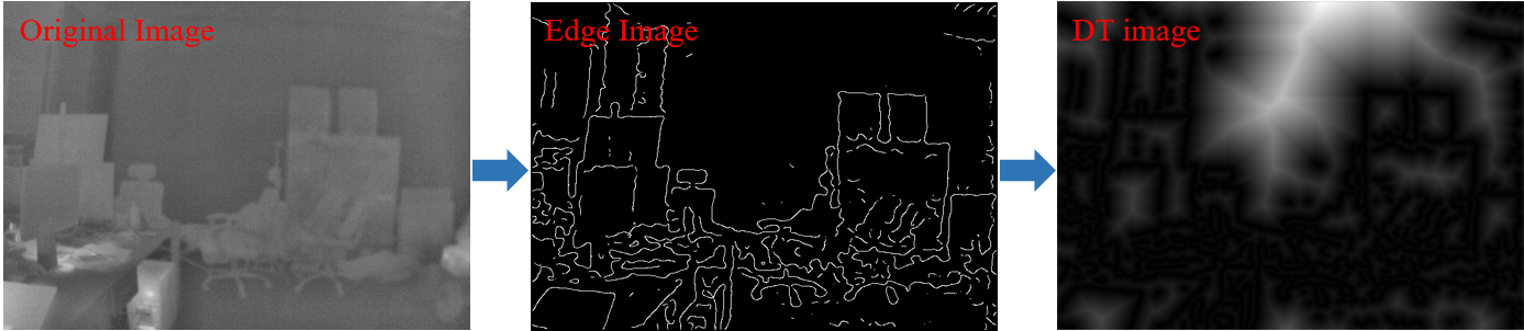
Distance Transform is an operator normally applied to binary images, describing the two-dimensional spatial distribution of edge points and usually appear as a distance field. As shown in Figure3a, the Distance Transform gives edge image a dense representation, in which the gray level is defined as the minimal distance to the nearest edge point for every pixel
| (5) |
where is the Euclidean distance between and the closest edge point , and is the binarized edge image.
Considering an edge point on the reference frame , the goal of DT-KLT tracker is to find the point on the current frame for maximum similarity. The 2D position displacement can be solved by minimizing the similarity function
| (6) |
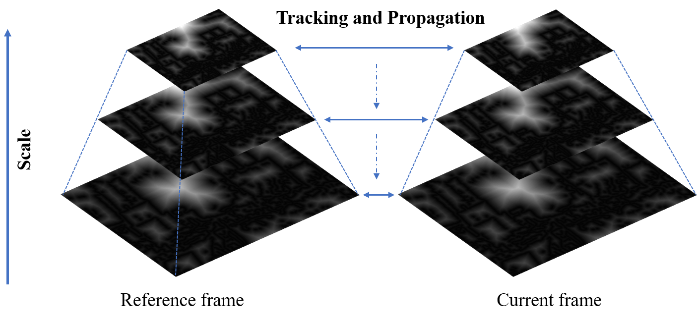
where and are the corresponding distance field for and . The above equation minimizes the distance distribution difference between two image patches of size () in distance field. A small patch size would be preferable for tracking accuracy, but difficult to handle large motions. For a trade-off between accuracy and robustness, image pyramidal implementation is utilized. The feature tracking is propagated from the highest to the lower level in scale‐space and so on up to the lowest as shown in Figure3b.
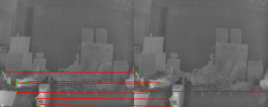
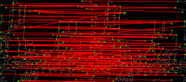
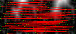
The feature tracking performance with different schemes is shown in Figure4. The standard KLT tracker can only track very few features for original thermal infrared images because of high image noise and low contrast. After utilizing the edge image for the association, tracking performance is improved significantly, but several wrong associations still exist due to sparse edge information. In comparison, our proposed DT-KLT tracker performs much better in tracking both tracking quantity and quality.
III-C Adaptive Feature Tracking Scheme
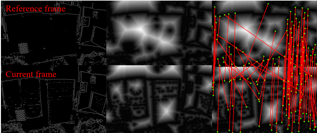
The previous subsection proves that applying distance transform can benefit the feature tracking performance on edge images. Compared with the standard KLT tracker, the DT-KLT algorithm is based on the distance field constancy assumption between consecutive frames. However, such an assumption will be broken under the following cases: 1) The camera’s view angle changes aggressively; 2) environmental photometric changes significantly. Both cases impact the edge extraction’s consistency and significantly change the distance field. Taking the photometric change as an example, the appearance of two consecutive frames is significantly different due to the abrupt change in environmental illumination. As shown in Figure5, the discontinuous edge extraction breaks the distance field consistency between the reference frame and current frame, resulting in the degradation of DT-KLT performance. Similarly, the more aggressive the camera rotates, the more unstable the distance field is.
Thus, the data association scheme affects the feature tracking robustness during thermal infrared camera motion and subsequently influences the accuracy of the odometry. In response to these cases by combining the standard KLT tracker and the proposed DT-KLT tracker, an adaptive feature tracking pipeline ADT-KLT is developed to switch data association schemes according to a distance field stability metric designed as
| (7) |
in which and are weight coefficients, and represents the normalized difference in the number of edge points extracted in the and as
| (8) |
The is defined as the relative rotation angle between and . According to Rodrigues’ rotation formula, the relative rotation matrix can be described as the rotation angle counterclockwise about a specified axis. The can be solved as
| (9) |
in which is the trace of the matrix, and can be gained from IMU pre-integration module, given as
| (10) |
where is the number of IMU measurements between and , is the th gyroscope measurement, is the gyroscope bias, and is the Gaussian white noise, is the duration between two IMU measurements, and satisfies
| (11) |
More specifically, a larger value of means that the dynamic change of the current distance field is more significant. Hence the adaptive switching policy is that when , the DT-KLT tracker is utilized on edge images association. Otherwise, a standard KLT tracker is utilized instead. is the adaptive threshold. The ablation experiment in the Subsection IV-A illustrates this adaptive policy’s effects, which helps improve localization accuracy.
III-D Tightly-Coupled Formulation
Robust edge feature tracking between thermal infrared frames is completed with the proposed ADT-KLT tracker, which is further utilized for reprojection error as
| (12) |
where is the variables to be estimated defined in Eq.(2), and and are the projected vector on the unit sphere of and , respectively; and are the th edge point tracked in the th and th frames by ADT-KLT tracker; and are two orthogonal bases of any choice that span the tangent plane of .
With the developed robust edge association, a bundle adjustment strategy is then utilized to fuse the measurements from IMU and thermal infrared images and implement the estimation of state .
The residuals for visual and IMU measurement, and , and the prior information from marginalization are minimized by sliding window optimization based on MAP. The objective function for the joint optimization is designed as follows
| (13) |
where and represent the measurement covariance matrices of the IMU and edge point, respectively. In addition, is the Huber norm function. And then, the Ceres solver[28] is used to solve this nonlinear optimization problem in Eq.(13). For more details about and , please refer to [1].
IV EXPERIMENTS
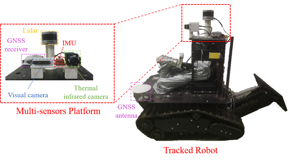
The proposed approach was verified with several experiments on public datasets and in the real world. As shown in Figure6, our self-designed tracked robot was utilized for real-world experiments with a multi-sensors device consisting of a GNSS device, a 3D Lidar, an IMU, a visual camera, and a thermal infrared camera. The corresponding specifications are listed in Table I. In addition, the onboard computer is an Intel NUC with an Intel i7-10710U processor.
| Type | Model | Description |
|---|---|---|
| Lidar | Velodyne VLP-16 | FOV with 10Hz |
| IMU | MTi-G-710 | 200Hz |
| GNSS | NovAtel | 20Hz |
| Visual Camera | Intel D435i | 640480px with 25Hz |
| Thermal Infrared Camera | Gobi+ 640 | 640480px with 50Hz |
IV-A Evaluation on the Public Datasets
We first evaluated our proposed approach on the Urban Parking Lot Dataset and the Active Gold Mine Dataset provided in [3]. Both datasets are collected by a DJI Matrice M100 quadrotor platform and combine thermal camera (Tau2), IMU (VN-100), and LiDAR (OS-1) measurements.
We compared our approach with state-of-the-art solutions, i.e. VINS-Mono[1], PL-VINS[18], ROTIO[3, 11], and ORB-SLAM3[27]. ROTIO is a modified version of ROVIO[29] for thermal infrared camera applications utilizing full radiometric data for initialization and tracking. The parameters of compared algorithms were set to the default values in the open-source codes and all results were obtained without loop-closure except for ORB-SLAM3. The latest LiDAR-inertial odometry FAST-LIO2[30] was utilized as the ground truth. The accuracy was evaluated by Root-Mean-Square-Error (RMSE) of Absolute Trajectory Error (ATE).
| Dataset | ORB-SLAM3 | VINS-Mono | PL-VINS | ROTIO | ETIO | ||
|---|---|---|---|---|---|---|---|
| KLT | DT-KLT | ADT-KLT | |||||
| the Urban Parking Lot | - | 4.892 | 3.594 | 2.934 | 2.136 | 1.049 | |
| the Active Gold Mine | - | 5.982 | 1.895 | 0.993 | 1.191 | 0.472 | |
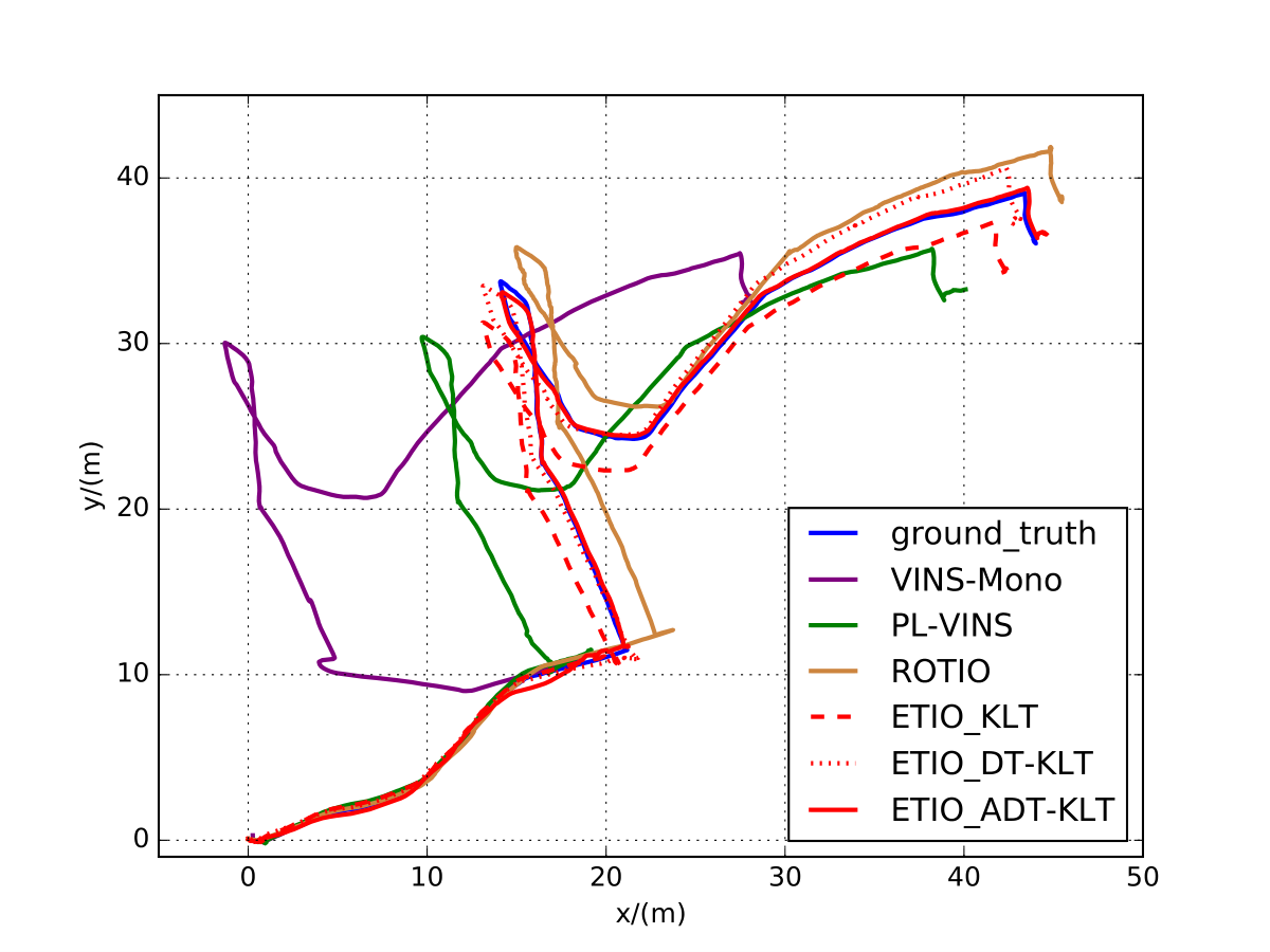
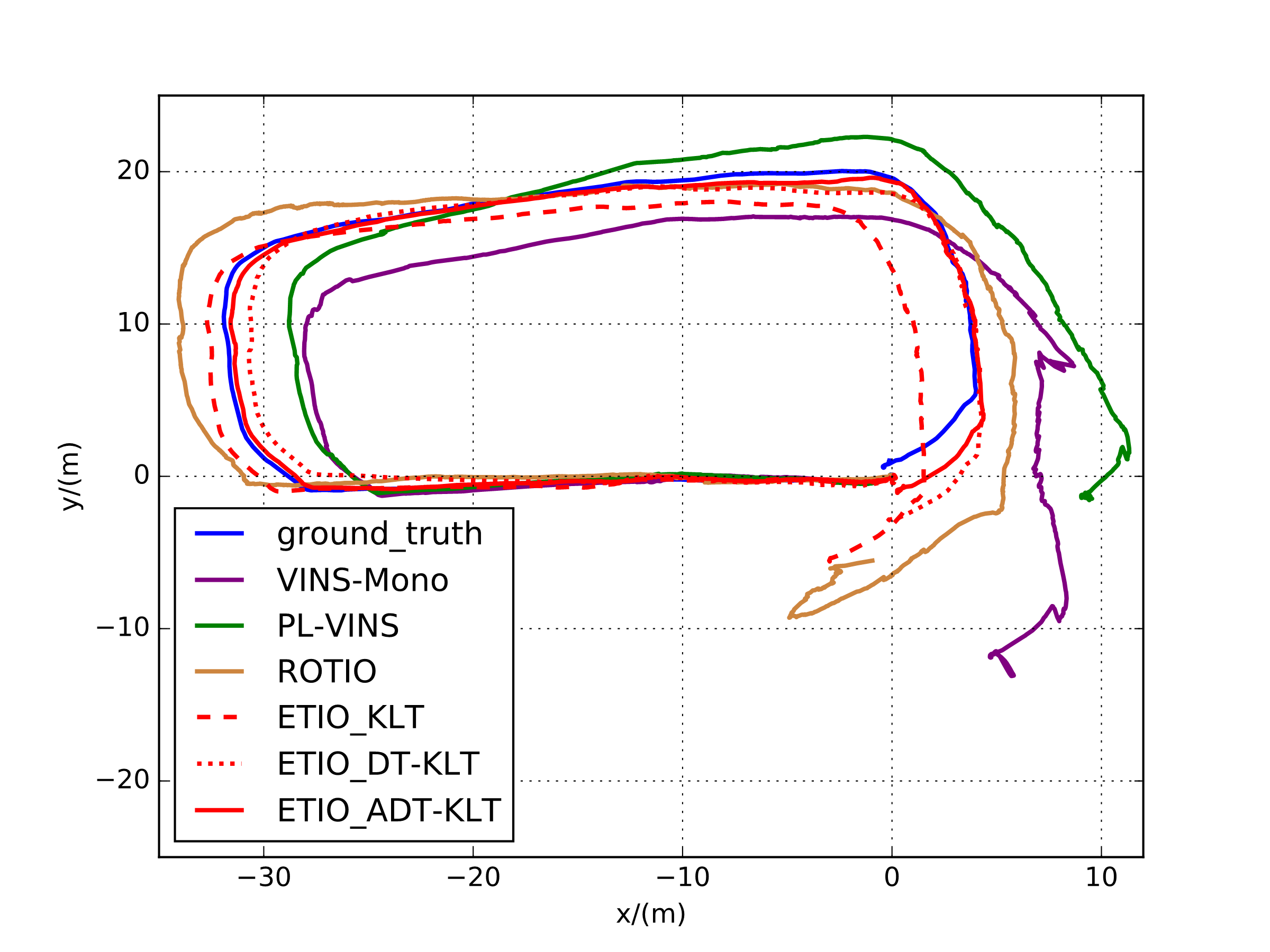
Figure 7 presents the comparative trajectories. Table II summarizes the estimation errors. The results show that our method outperforms the other open-source solutions. Because of low contrast and high noise, ORB-SLAM3 failed to provide completed trajectory information in both datasets. It is seen that the lack of distinctive feature detection increases the number of false positives in the descriptor matching. VINS-Mono relying on optical flow for feature tracking, performed robust to image quality but is susceptible to photometric changes suddenly caused by NUC or rescaling operation. PL-VINS exploited structural constraints for a supplement but with limited performance enhancement. The proposed ETIO performed the best in both datasets, benefiting from the robust edge-based data association scheme. Inferring that the impact of noise and NUC is relatively small for the full radiometric data but not negligible, ROTIO performed better than conventional VIO methods but worse than ETIO.
Then, we performed an ablation study to show the effects of the proposed ADT-KLT tracker. We evaluated the performance of the three data association methods, i.e., the standard KLT tracker, the DT-KLT tracker, and the ADT-KLT tracker. As shown in Table II, both the DT-KLT tracker and ADT-KLT tracker performed better than the standard KLT tracker, which validated that the distance field can efficiently improve the edge feature tracking. ADT-KLT tracker obtained the best performance because the proposed adaptive policy can suppress the tracking loss caused by sudden changes in the distance field.
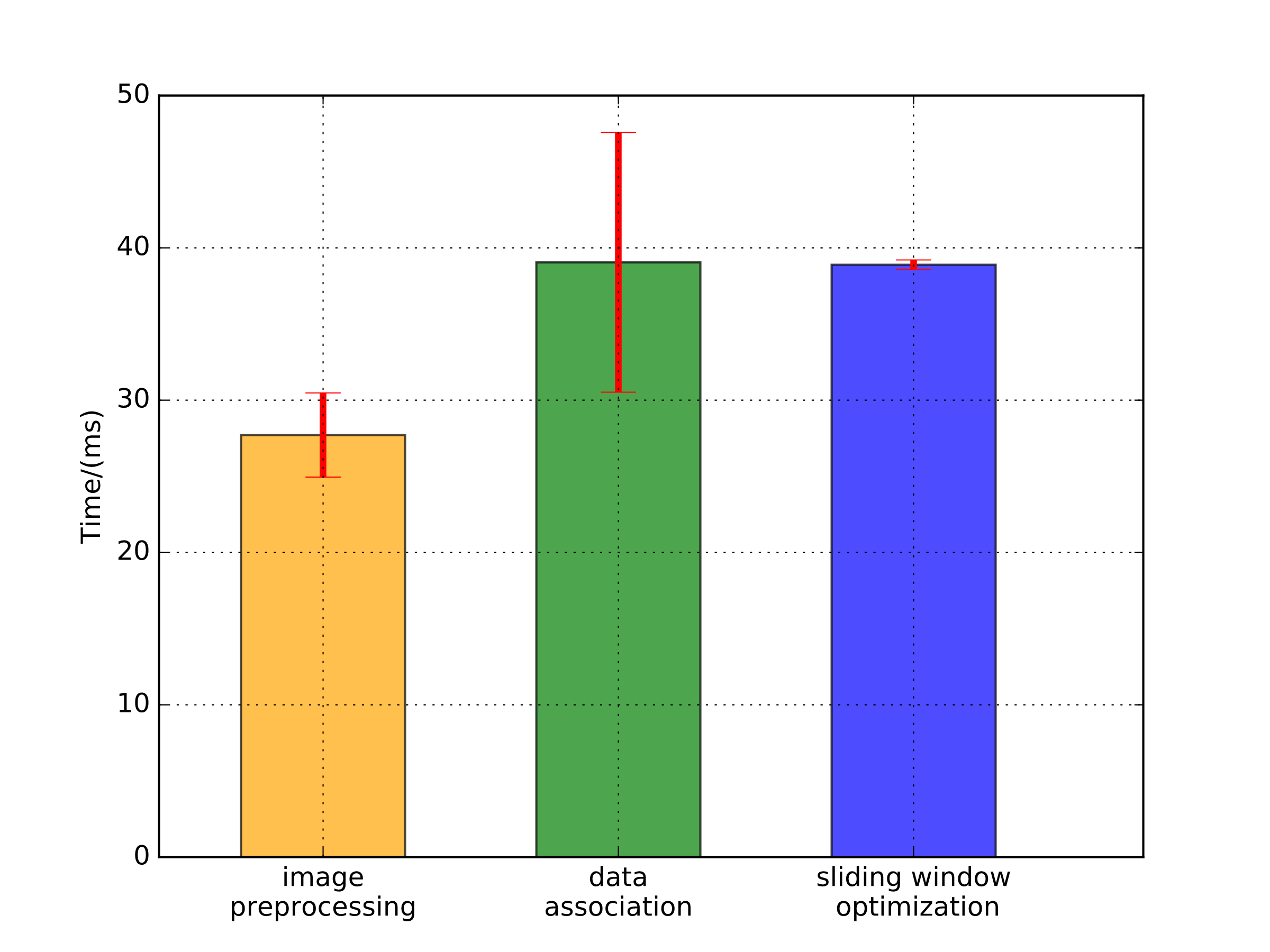
To quantitatively evaluate the real-time performance of the system, we also recorded the time consumption of all the sequences for analysis. The time consumption statistics with a mean and a standard deviation per round for each component are shown in Figure8. It is seen that the proposed ETIO exhibits real-time performance because parallel computation and multithreading technologies are adopted for different modules. The state update frequency is determined by the highest execution time in the three threads. The maximum output frequency of the odometer is about 25Hz so that our approach can work in real-time without GPU acceleration.
IV-B Evaluation in Outdoor Environments
A real-world experiment was further performed in an outdoor urban environment to evaluate the all-day localization accuracy of ETIO. The tracked robot in Figure6 was manually controlled to run similar trajectories in the park, and four sequences were recorded at different times of the day shown in Table III. The total path length of each sequence is approximately 200 m, and the GNSS and Lidar provided the ground truth of trajectories.
Unlike the scenes in the previous subsection, which are mainly indoors or in caves, TIO is more challenging in outdoor scenes where the thermal infrared image is affected by the solar radiation. The estimated trajectories are shown in Figure9. Noticed that ROTIO performed much worse than the evaluation of Subsection IV-A, and even failed in Seq.01. Quantitative results of trajectory error are presented in Table III. The heat accumulation from solar radiation caused the image to saturate, resulting in inconsistent patch tracking and state estimate divergence. At night sequence, the sun’s radiation got weaker, making the thermal radiation of different objects outdoors more distinguishable. Hence, the performance of ROTIO improved as the night fell.
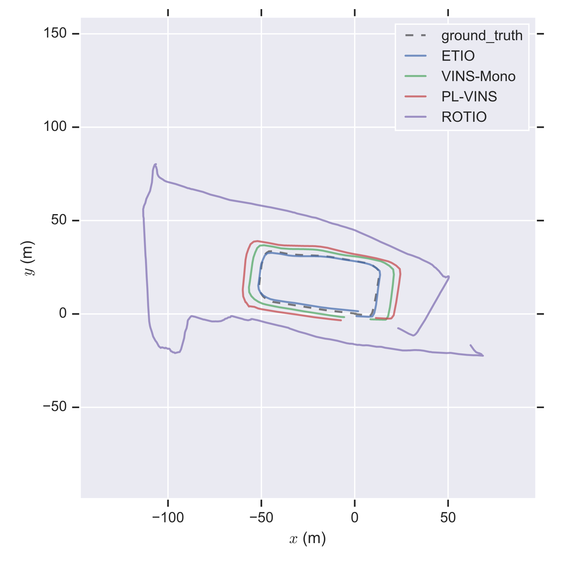
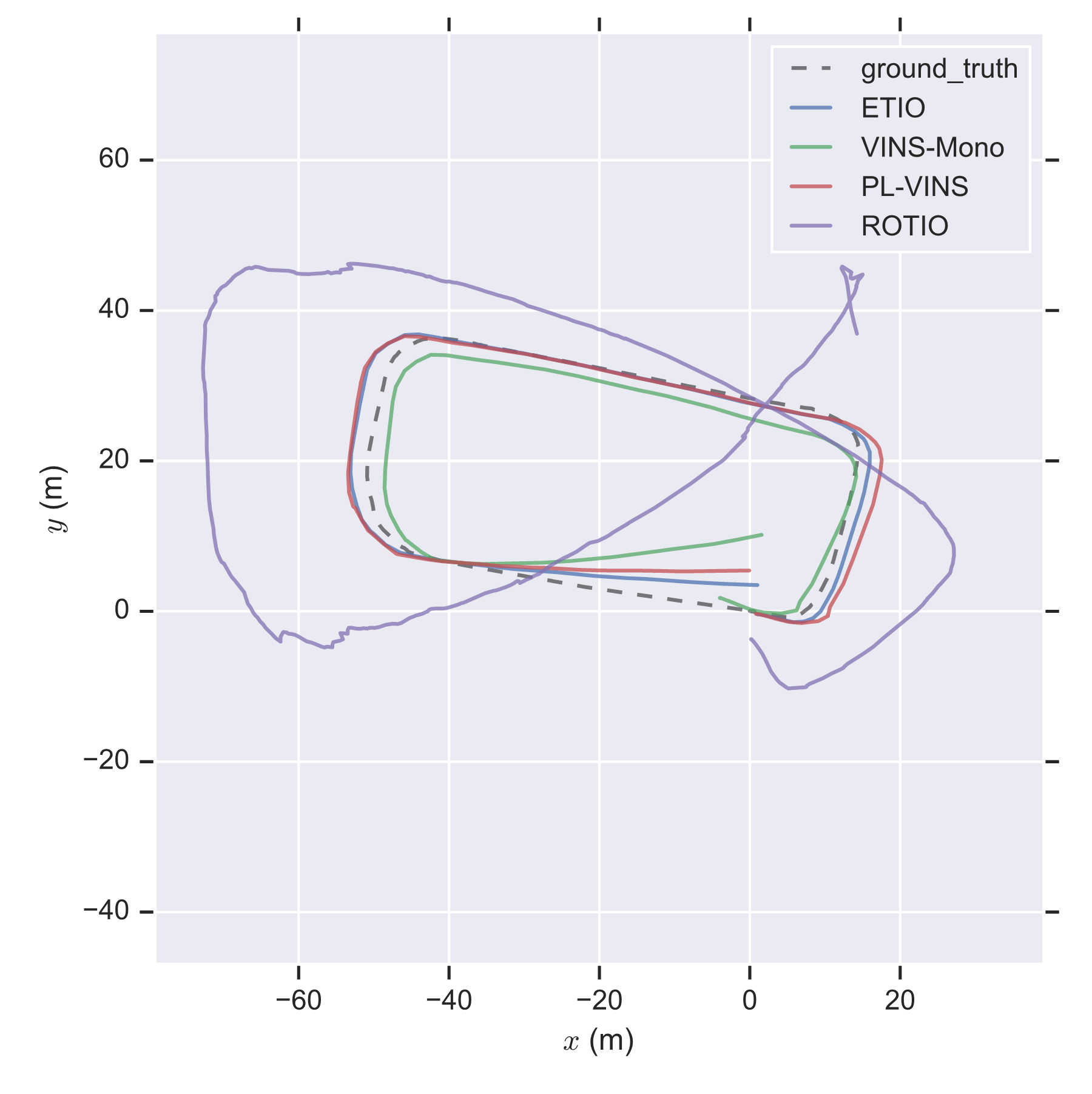
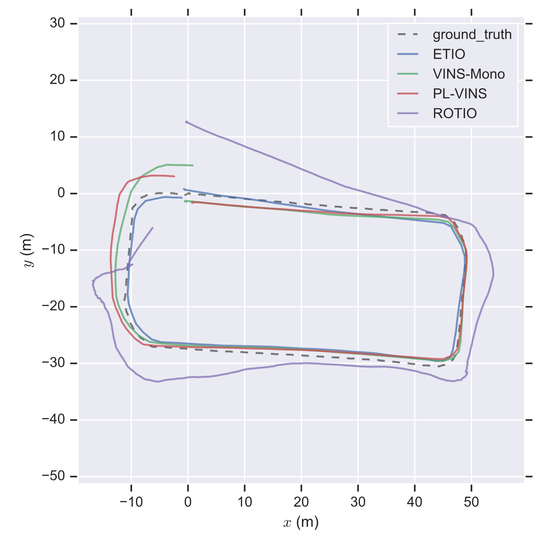
Compared with ROTIO, the other mentioned approaches performed more robust to illumination changes during the all-day time and provided continuous trajectories. Line feature detection and matching introduce errors due to low image quality. For this reason, PL-VINS, which makes additional use of the line feature constraints compared to VINS-Mono, was not performing better than VINS-Mono. ETIO presented the best performance among all the sequences, which validates that the proposed edge-based method achieves robust all-day localization ability.
| Seq | Time of day | VINS-Mono | PL-VINS | ROTIO | ETIO |
|---|---|---|---|---|---|
| 01 | Day(14:57) | 3.301 | 4.101 | - | |
| 02 | Dusk(18:27) | 6.263 | 9.338 | 41.330 | |
| 03 | Night(21:08) | 4.296 | 2.636 | 18.058 | |
| 04 | Night(23:15) | 2.166 | 2.286 | 8.880 |
IV-C Evaluation in Extreme Environment
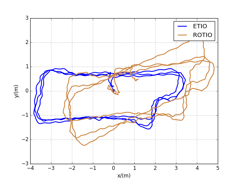
The proposed approach was deployed in a dark, smoke-filled room for evaluation in extreme illumination environments such as conflagration areas. The artificial smoke was added to make the environment more degraded, created by a theatrical smoke generator. We held the sensor platform in hand, walked around the specified trajectory, and eventually returned to the starting point. Two sequences with different path lengths were recorded. As VICON or Lidar-based state estimation approaches cannot work for ground truth output in such an environment, trajectory accuracy was evaluated by accumulated drift.
| Seq | Length (m) | VINS-Mono | PL-VINS | ROTIO | ETIO |
|---|---|---|---|---|---|
| 01 | 73.2 | - | - | 1.035 | |
| 02 | 54.3 | - | - | 0.746 |
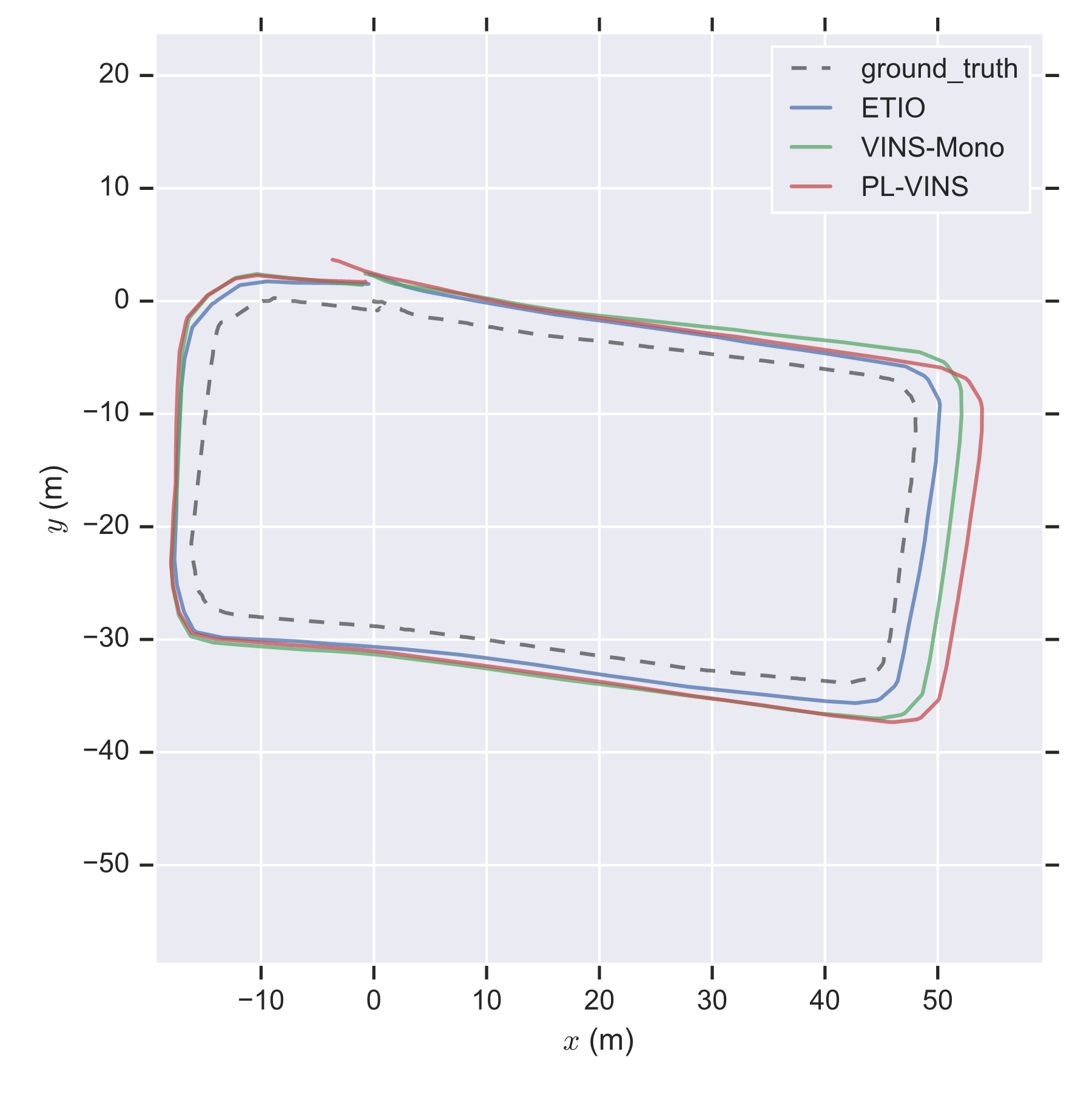
The error statistics are shown in Table IV, and our method outperforms the others in both sequences, where VINS-Mono and PL-VINS both failed. Take Seq.01 as an example, and the estimated trajectories are shown in Figure10. ROTIO achieved continuous estimation of camera trajectories but exhibited a significant error in the yaw angle estimation, especially during turning; we infer that it’s because the thermal infrared images had a significant appearance change when turning, leading to data association errors. In contrast, ETIO performed better trajectory consistency benefitting from our robust edge-based data association solution.
V Conclusions
Compared with the visual camera, the thermal infrared camera has the potential to work all-day time. Motivated by the phenomenon that thermal radiation varies most significantly at the edges of objects, the study proposes an edge-based monocular thermal-inertial odometry, called ETIO, to salient edge information for robust state estimation in visually degraded environments. Distance field-aided feature tracking and an adaptive switching policy are proposed to overcome the difficulties of sparse edge image data association. Extensive evaluations indicated the reliable and robust performance of the proposed method for state estimation in visually degraded environments.
Considering that the edge information is also relatively robust for visual images, we believe that edge features are the bridge of tightly coupled visual and thermal infrared streams for state estimation. In future work, we aim to exploring the applications in edge-based visual-thermal-inertial fusion framework.
References
- [1] T. Qin, P. Li, and S. Shen, “Vins-mono: A robust and versatile monocular visual-inertial state estimator,” IEEE Transactions on Robotics, vol. 34, no. 4, pp. 1004–1020, 2018.
- [2] L. von Stumberg and D. Cremers, “Dm-vio: Delayed marginalization visual-inertial odometry,” IEEE Robotics and Automation Letters, vol. 7, no. 2, pp. 1408–1415, 2022.
- [3] S. Khattak, C. Papachristos, and K. Alexis, “Keyframe-based thermal–inertial odometry,” Journal of Field Robotics, vol. 37, no. 4, pp. 552–579, 2020.
- [4] A. Banuls, A. Mandow, R. Vázquez-Martín, J. Morales, and A. García-Cerezo, “Object detection from thermal infrared and visible light cameras in search and rescue scenes,” in 2020 IEEE International Symposium on Safety, Security, and Rescue Robotics (SSRR). IEEE, 2020, pp. 380–386.
- [5] Y.-S. Shin, Y. S. Park, and A. Kim, “Dvl-slam: Sparse depth enhanced direct visual-lidar slam,” Autonomous Robots, vol. 44, no. 2, pp. 115–130, 2020.
- [6] O. Riou, S. Berrebi, and P. Bremond, “Nonuniformity correction and thermal drift compensation of thermal infrared camera,” Proceedings of SPIE - The International Society for Optical Engineering, vol. 5405, 2004.
- [7] A. Beauvisage, N. Aouf, and H. Courtois, “Multi-spectral visual odometry for unmanned air vehicles,” in 2016 IEEE International Conference on Systems, Man, and Cybernetics (SMC). IEEE, 2016, pp. 001 994–001 999.
- [8] J. Poujol, C. A. Aguilera, E. Danos, B. X. Vintimilla, R. Toledo, and A. D. Sappa, “A visible-thermal fusion based monocular visual odometry,” in Robot 2015: Second Iberian Robotics Conference. Springer, 2016, pp. 517–528.
- [9] T. Mouats, N. Aouf, L. Chermak, and M. A. Richardson, “Thermal stereo odometry for uavs,” IEEE Sensors Journal, vol. 15, no. 11, pp. 6335–6347, 2015.
- [10] Y.-S. Shin and A. Kim, “Sparse depth enhanced direct thermal-infrared slam beyond the visible spectrum,” IEEE Robotics and Automation Letters, vol. 4, no. 3, pp. 2918–2925, 2019.
- [11] H. D. Flemmen, “Rovtio: Robust visual thermal inertial odometry,” Master’s thesis, NTNU, 2021.
- [12] S. Zhao, P. Wang, H. Zhang, Z. Fang, and S. Scherer, “Tp-tio: A robust thermal-inertial odometry with deep thermalpoint,” in 2020 IEEE/RSJ International Conference on Intelligent Robots and Systems (IROS). IEEE, 2020, pp. 4505–4512.
- [13] M. R. U. Saputra, P. P. de Gusmao, C. X. Lu, Y. Almalioglu, S. Rosa, C. Chen, J. Wahlström, W. Wang, A. Markham, and N. Trigoni, “Deeptio: A deep thermal-inertial odometry with visual hallucination,” IEEE Robotics and Automation Letters, vol. 5, no. 2, pp. 1672–1679, 2020.
- [14] M. R. U. Saputra, C. X. Lu, P. P. B. de Gusmao, B. Wang, A. Markham, and N. Trigoni, “Graph-based thermal–inertial slam with probabilistic neural networks,” IEEE Transactions on Robotics, 2021.
- [15] J. Jiang, X. Chen, W. Dai, Z. Gao, and Y. Zhang, “Thermal-inertial slam for the environments with challenging illumination,” IEEE Robotics and Automation Letters, vol. 7, no. 4, pp. 8767–8774, 2022.
- [16] D. DeTone, T. Malisiewicz, and A. Rabinovich, “Superpoint: Self-supervised interest point detection and description,” in Proceedings of the IEEE conference on computer vision and pattern recognition workshops, 2018, pp. 224–236.
- [17] W. Y. Jeong and K. M. Lee, “Visual slam with line and corner features,” in 2006 IEEE/RSJ international conference on intelligent robots and systems. IEEE, 2006, pp. 2570–2575.
- [18] Q. Fu, J. Wang, H. Yu, I. Ali, F. Guo, Y. He, and H. Zhang, “Pl-vins: Real-time monocular visual-inertial slam with point and line features,” arXiv preprint arXiv:2009.07462, 2020.
- [19] D. Zhou, Y. Dai, and H. Li, “Ground-plane-based absolute scale estimation for monocular visual odometry,” IEEE Transactions on Intelligent Transportation Systems, vol. 21, no. 2, pp. 791–802, 2019.
- [20] W. Chen, Y. Wang, H. Chen, and Y. Liu, “Eil-slam: Depth-enhanced edge-based infrared-lidar slam,” Journal of Field Robotics, vol. 39, no. 2, pp. 117–130, 2022.
- [21] J. J. Tarrio and S. Pedre, “Realtime edge-based visual odometry for a monocular camera,” in Proceedings of the IEEE International Conference on Computer Vision, 2015, pp. 702–710.
- [22] F. Schenk and F. Fraundorfer, “Robust edge-based visual odometry using machine-learned edges,” in 2017 IEEE/RSJ International Conference on Intelligent Robots and Systems (IROS). IEEE, 2017, pp. 1297–1304.
- [23] ——, “Reslam: A real-time robust edge-based slam system,” in 2019 International Conference on Robotics and Automation (ICRA). IEEE, 2019, pp. 154–160.
- [24] Y. Zhou, H. Li, and L. Kneip, “Canny-vo: Visual odometry with rgb-d cameras based on geometric 3-d–2-d edge alignment,” IEEE Transactions on Robotics, vol. 35, no. 1, pp. 184–199, 2018.
- [25] C. Forster, L. Carlone, F. Dellaert, and D. Scaramuzza, “On-manifold preintegration theory for fast and accurate visual-inertial navigation,” IEEE Transactions on Robotics, pp. 1–18, 2015.
- [26] C. Bhabatosh et al., Digital image processing and analysis. PHI Learning Pvt. Ltd., 2011.
- [27] C. Campos, R. Elvira, J. J. G. Rodríguez, J. M. Montiel, and J. D. Tardós, “Orb-slam3: An accurate open-source library for visual, visual–inertial, and multimap slam,” IEEE Transactions on Robotics, vol. 37, no. 6, pp. 1874–1890, 2021.
- [28] S. Agarwal, K. Mierle, and T. C. S. Team, “Ceres Solver,” 3 2022. [Online]. Available: https://github.com/ceres-solver/ceres-solver
- [29] M. Bloesch, M. Burri, S. Omari, M. Hutter, and R. Siegwart, “Iterated extended kalman filter based visual-inertial odometry using direct photometric feedback,” The International Journal of Robotics Research, vol. 36, no. 10, pp. 1053–1072, 2017.
- [30] W. Xu, Y. Cai, D. He, J. Lin, and F. Zhang, “Fast-lio2: Fast direct lidar-inertial odometry,” IEEE Transactions on Robotics, 2022.