Scalable Framework for Deep Learning based CSI Feedback
Abstract
Deep learning (DL) based channel state information (CSI) feedback in multiple-input multiple-output (MIMO) systems recently has attracted lots of attention from both academia and industrial. From a practical point of views, it is huge burden to train, transfer and deploy a DL model for each parameter configuration of the base station (BS). In this paper, we propose a scalable and flexible framework for DL based CSI feedback referred as scalable CsiNet (SCsiNet) to adapt a family of configured parameters such as feedback payloads, MIMO channel ranks, antenna numbers. To reduce model size and training complexity, the core block with pre-processing and post-processing in SCsiNet is reused among different parameter configurations as much as possible which is totally different from configuration-orienting design. The pre-processing and post-processing are trainable neural network layers introduced for matching input/output dimensions and probability distributions. The proposed SCsiNet is evaluated by metrics of squared generalized cosine similarity (SGCS) and user throughput (UPT) in system level simulations. Compared to existing schemes (configuration-orienting DL schemes and 3GPP Rel-16 Type-II codebook based schemes), the proposed scheme can significantly reduce mode size and achieve UPT improvement for all parameter configurations.
Index Terms:
MIMO, CSI feedback, deep learning, scalable framework.I Introduction
Massive multiple-input multiple-output (MIMO) is a promising technology to improve spectrum efficiency and system throughput in wirelss communication systems. However, accurate acquisition and feedback of channel state information (CSI) is the key to ensure a good performance of massive MIMO systems. In the fifth generation new radio (5G NR) system, eigenvectors (pre-coding vectors) of downlink MIMO channels are acquired based on CSI reference signals (CSI-RS) at user equipments (UEs) and return to the base station (BS) via uplink channels. To reduce feedback overheads, the correlation of eigenvectors in the frequency domain is exploited by enhanced Type II (eType II) codebooks defined in [1].
Recently deep learning (DL) based CSI feedback has attracted lots of attention from both academia and industrial due to its potential to improve feedback accuracy, reduce feedback overhead and delay [2]. An auto-encoder (encoder-decoder network) called CsiNet was firstly introduced by [3] to compress MIMO full channels where encoder part and decoder part are mainly constructed by convolutional neural networks (CNNs) with a residual structure. Simulation results show that CsiNet outperforms traditional schemes based on compressed sensing algorithms. Inspired by this pioneering work, the temporal correlation and reciprocity between the uplink and the downlink are utilized by CsiNet-LSTM [4] and DualNet-MAG/ABS [5] to further improve feedback performances. Different from above-mentioned schemes concentrating on the feedback of MIMO full channels, the EVCsiNet proposed in [6] considers the feedback of channel eigenvectors and shows the superiority over the scheme based on eType II codebooks.
In existing DL based schemes for CSI feedback, all DL models are designed orienting to a specific scenario and configuration. This means that the number of DL models is at least proportional to the number of configured parameters which will significantly increase the burden of model training, model transferring and model deployment. For example, depending on the capacity of uplink channel, the network may prefer different CSI feedback payload size. The payload size ranges from tens of bits to hundreds of bits. In addition, the BS can be equipped with different number of antenna ports, e.g., 4, 8, 12, 32 etc. The network can also have preference on the number of data layers depending on channel condition. Therefore, we may need DL models for feedback overheads of -bits, MIMO ranks of , and antenna port numbers of {4,8,12,16,24,32} even if other wireless communication scenarios/configurations are ignored (e.g., urban macro, urban micro, rural macro, indoor hotspot). It is unaffordable for UEs to support so many DL models from storage perspective. This motivates us to design a scalable and flexible framework for DL based CSI feedback.
In this paper, we will give a scalable and flexible framework for DL based eigenvectors feedback to adapt a family of parameter configurations called scalable CsiNet (SCsiNet). Our SCsiNet is designed as a multi-branch structure and core blocks are shared/reused among all configurations to reduce model size which is totally different from conventional configuration-orienting design. We also provide training scheme for SCsiNet and a payload allocation scheme for different MIMO layers and ranks. Simulation results show that the proposed SCsiNet can achieve a better performance under the same feedback payload compared to the scheme based on eType II codebooks.
The main contribution of this paper is summarized as follows.
-
•
A scalable and flexible framework for DL based eigenvectors feedback is designed based on a multi-branch structure to adapt a family of parameter configurations, e.g., feedback payload, MIMO ranks, antenna ports. The core block in SCsiNet is reused among all parameter configurations and all DL models can be unified into single one.
-
•
With this scalable and flexible framework, rank-adaptive payload allocation is introduced to ensure performances and payload requirements for different ranks.
-
•
To evaluate the proposed SCsiNet, we give squared generalized cosine similarity (SGCS) performances and downlink user throughput (UPT) performances in system level simulations.
II System model and existing scheme
In this paper, we consider a downlink MIMO-OFDM system with transmit antennas at the BS and receive antennas at UEs. Let denotes channel matrix, subband level channel eigenvectors can be expressed as
| (1) |
for , where and are the numbers of sub-carriers and sub-bands respectively, and each sub-band consists of sub-carriers. denotes eigenvectors of associated with the largest eigenvalues, is the correlation matrix of -th sub-band. Similar to [6], we also use SGCS to evaluate recovery accuracy of the eigenvectors, which is defined as
| (2) |
where denote the -th column of i.e. the eigenvector of -th sub-band and -th layer, is the reconstructed eigenvector corresponding to , .
II-A 3GPP eType II codebook based eigenvector feedback
For an eType II codebook based feedback, sub-band level eigenvectors are first compressed to reduce their dimensions, then complex values in low dimension are quantized to a binary stream at UE. At the BS, the binary stream is dequantized and then used to reconstruct eigenvectors. For the -th layer, the reconstructed eigenvectors of all sub-bands can be expressed by
| (3) |
where is spatial beam matrix reflecting long-term and wide-band characteristics, is frequency compression matrix, and is the dequantized result of a binary stream. The value of is determined by frequency compression rate configured by the BS. The spatial beam matrix and frequency compression matrix are all made up of DFT vectors, is shared by all layers but is layer-specific.
II-B DL based eigenvector feedback
In [6], EVCsiNet is proposed for for eigenvector feedback. This is a typical configuration-orienting design. Let denote eigenvectors associated with the largest eigenvalues for all sub-bands. EVCsiNet tries to compress and quantize into binary bits and reconstruct it as follows
| (4) |
where and denote the encoder part and the decoder part, and denote the quantizer and the dequantizer. The parameters of and are obtained by optimizing
| (5) |
at the training phase. Considering the implementation complexity of encoder at the UE side, lightweight architecture is adopted with two fully-connected layers in the encoder part of EVCsiNet.
III Proposed SCsiNet
Various payloads, ranks and antenna numbers should be supported as that for eType II codebooks in the 5G NR system. To this end, a trivial way is configuration-orienting design but the complexity of model training, storage and transferring would be increased linearly with the number of configurations. A alternative way is to propose a scalable and flexible framework and all DL models are unified into single one. In this section, this framework, i.e. SCsiNet will be introduced in detail.
III-A SCsiNet

As shown in Fig.1, the SCsiNet is a “layer-common” model which ignores the layer index of eigenvector inputs. In other words, for any , eigenvectors from -th layer and sub-bands are fed into the same SCsiNet. To adapt a family of parameter configurations, SCsiNet is designed as a multiple branch structure where each split branch corresponds to the specific value of a parameter. The core block (EN/DE block) has multiple branches inside or outside, and is also connected with multiple blocks (US/DS block or LPT/LT block). These connected blocks are regarded as pre-processing or post-processing with the respect to core blocks.
Specifically, down-sampling/up-sampling (DS/US) blocks are introduced to support various feedback payloads. DS- block and US- block are linear transformations for down-sampling and up-sampling, respectively. The output range of DS- block is restricted to with a sigmoid activation function for the convenience of quantization. Also, 2-bits scalar uniform quantizer and dequantizer are embedded into DS- block and US- block respectively. A pair of DS- block and US- block corresponds to a payload configuration of -bits, and multiple pairs of DS- block and US- block ensure that the proposed SCsiNet is payload-scalable. Moreover, the linear pre-transform/transform (LPT/LT) blocks are introduced for the propose of unifying input/output dimensions and probability distributions of eigenvectors from different antenna number . LPT- block is a linear transformation for eigenvectors of antenna number at the spatial domain which transforms its input into a common domain while LT- block transforms its inputs back into the original eigenvector domain of antenna number . It is worth noting that all above linear transformations are realized by trainable fully-connected layers. Two core blocks of EN block and DE block are shared among all branches, also parameter configurations. They are made up of several transformer encode blocks with parallel attention layers, and the pre-normalization version in [8] is adopted to facilitate training.
The detailed design of all blocks in SCsiNet is shown at the bottom of Fig.1. For LPT- block, the input is eigenvectors from all sub-bands (2 means real part and imaginary part of a complex number) for -th layer, is linearly embedded into a higher dimension of by a fully-connected layer with units. In LT- block, a fully-connected layer is also used with units and a tanh activation function because the range of eigenvectors is between -1 and 1. As mentioned above, transformer encode blocks and transformer encode blocks with pre-normalization are respectively used in EN block and DE block after positional encoding. The attention mechanism in transformer encode blocks can help to extract the correlation of eigenvectors among sub-bands. Since the size is not changed, the input dimension and the output dimension of EN block and DE block are . The detail of transformer encode block and positional encoding can refer to [7]. In DS- block, the input of size is firstly flatten into the dimension of , then reduced to the dimension of by a fully-connected layer with units, and feedback bits are obtained by quantizing the output of this fully-connected layer. As for US- block, feedback bits are dequantized to real numbers whose range is . The “lambda layer” is used to map the range from to which can be described by the element-wise operation of . Similarly, a full-connected layer with units is used for up-sampling. The hyper-parameters of SCsiNet are given in Table.I. For simplicity, we only consider the case of in this paper. Since the BS is more powerful, the SCsiNet may be deigned as .
| Parameter | |||||
|---|---|---|---|---|---|
| Value | 8 | 12 | 4 | 128 | 2 |
| Parameter | |||||
| Value | 2 | {20,40,60,…,320} | {16,32} |
III-B Training of SCsiNet
The training process can be generally described by optimizing the following formula
| (6) |
where denotes the reconstructed result of -bits payload. It can be seen that given layer index , the loss function is the average SGCS over all payloads. At the training phase, the eigenvectors from all layers will be fed into SCiNet ignoring layer index . For various antenna number , a nature way to train the SCsiNet is to feed training data with different antenna number in turn which can be described by Algorithm.1. To reduce training complexity, a three-stage training approach is used in this paper. At the first stage, the SCsiNet is only optimized by eigenvectors from antenna number. Then a pair of LPT- and LT- () is optimized at the second stage after EN block, DE block, DS- block s and US- blocks are frozen (i.e., the weights are not updated by the optimizer). Fine-tuning is adopted with few epochs based on Algorithm.1 at the final stage.
Input:
Supported antenna numbers ,
training data for ,
Batch size
III-C Inference of SCsiNet
At the inference phase, only one branch in Fig.1 will be activated according to the configured parameter. For example, a path of “LPT-16 blockEN blockDS-120 blockUS-120 blockDE blockLT-16 block” will be activated for the configuration of transmit antenna number , 120-bits feedback payload. For any layer, eigenvectors of all sub-bands are fed into the encoder part of SCsiNet for compression. Since two core blocks (EN block and DE block) are shared among all configurations and transformer encode block is usually much bigger than other blocks, the model size of the proposed SCsiNet will be superior to the configuration-orienting DL based scheme (i.e., each configuration is equipped with a DL model).
IV Simulation results
In this section, we give simulation results of SCsiNet, conventional configuration-orienting DL schemes and eType II codebook based schemes in system level simulations. We adopt the channel model defined by 3GPP TR38.901 with urban macro (UMa) scenario, 2GHz carrier frequency and 15kHz subcarrier spacing. We consider 48 physical resource blocks (PRBs) and sub-bands (i.e., 4PRBs per sub-band for eigenvector feedback). The more detail of channel modeling parameters is given in Appendix. The data set is builded by eigenvectors of antenna number and MIMO layers from 50 drops (random seeds), 57 cells and 570 UEs (10 UEs per cell). To improve the diversity of data set, we collect eigenvectors under the service of full buffer because all UEs in a cell will perform channel measurement and eigenvector feedback. The collected data set is divided into training data set and test data set according to their drops which have the size of and () per MIMO layer, respectively. In fact, there are two kinds of eigenvectors in simulations as follows
-
•
Ideal eigenvectors which are obtained by singular value decomposition (SVD) of known channel matrices;
-
•
Realistic eigenvectors which are obtained by SVD of estimated channel matrices corrupted by the noise and the interference.
In this paper, ideal eigenvectors are used for both inputs and labels at the training stage. However, at the inference stage, realistic eigenvectors are fed into DL models and the performance is evaluated by the SGCS between reconstructed eigenvectors and ideal eigenvectors. Before fed to DL models, the eigenvectors will be normalized by the maximum amplitude in , i.e. . At the first two training stages, the adaptive momentum (Adam) optimizer with the learning rate of [7] is adopted for 200 and 100 epochs, respectively. And at the fine-tuning stage, the Adam optimizer with cosine annealing learning rate of is adopted for 30 epochs.
IV-A SCsiNet versus configuration-orienting DL scheme
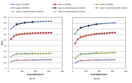
Fig.2 shows SGCS performances of SCsiNet and conventional configuration-orienting DL schemes for various payloads and 4 layers. In conventional DL schemes, each DL model is “layer-common” and trained by mixed eigenvectors from layers for a specific payload and antenna number. In this figure, -bits payloads and antenna numbers are considered and the total number of DL models is for conventional DL schemes. It can be observed from simulation results that the proposed SCsiNet has a similar performance compared to conventional DL schemes for 4 layers and different payloads. If -bits payloads and antenna numbers are considered, the number of DL models will even become for conventional schemes. However, the proposed SCsiNet can adapt these payloads and antenna numbers with single DL model and small model size.
IV-B SCsiNet versus eType II codebook based scheme
| Configuration | Rank1 | Rank2 | Rank3 | Rank4 |
|---|---|---|---|---|
| 1 | 40 | 60,20 | 40,20,20 | 40,20,20,20 |
| 2 | 60 | 80,40 | 60,40,20 | 60,20,20,40 |
| 3 | 80 | 100,60 | 80,40,40 | 80,40,20,40 |
| 4 | 120 | 160,80 | 100,80,60 | 120,60,40,40 |
| 5 | 160 | 220,100 | 160,120,80 | 160,100,60,60 |
| 6 | 240 | 320,140 | 180,140,120 | 180,140,80,60 |
In wireless systems, the performance gain of increasing eigenvector feedback accuracy for high ranks is much lower than that of low ranks, and the probability of scheduling UEs with high ranks is also much lower with the respect to low ranks. Therefore, allocating more payloads for high ranks than low ranks is not a good choice. In the 5G NR system, feedback payload of rank=2,3,4 is approximately twice compared to rank=1. Thanks to the scalable and flexible framework, the payload allocation among different layers and ranks can be easily realized by SCsiNet. Table.II gives payload allocation among 4 layers for different ranks.
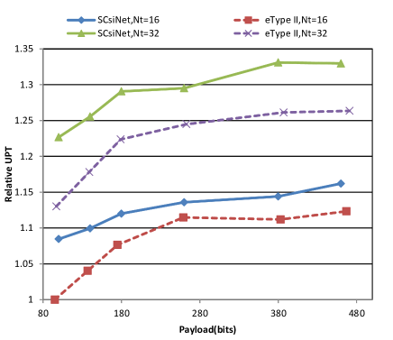
Fig.3 shows UPT performances of SCsiNet and eType II codebook based schemes for and various payloads. The SCsiNet is deployed into system level simulations with C/C++ interface of deep learning platform. Rank adaptive schedule and FTP model 1 service are adopted and packet size is 0.5Mbytes. It can be seen from Fig.3 that the proposed SCsiNet outperforms the eType II codebook based scheme for antenna number and all payloads. Under the same feedback payload, the proposed SCsiNet can achieve approximately UPT improvement.
IV-C FLOPs and model parameters
| Payload(bits) | 20 | 40 | 60 | 80 | 100 | 120 |
| , encoder | 9.8 | 9.84 | 9.87 | 9.9 | 9.93 | 9.96 |
| , decoder | 9.8 | 9.84 | 9.87 | 9.9 | 9.93 | 9.96 |
| , encoder | 9.9 | 9.93 | 9.97 | 10 | 10 | 10.06 |
| , decoder | 9.9 | 9.93 | 9.96 | 10 | 10.03 | 10.06 |
| Payload(bits) | 140 | 160 | 180 | 200 | 220 | 240 |
| , encoder | 9.96 | 10.02 | 10.1 | 10.08 | 10.11 | 10.14 |
| , decoder | 9.96 | 10.02 | 10.05 | 10.08 | 10.11 | 10.14 |
| , encoder | 10.06 | 10.12 | 10.15 | 10.18 | 10.21 | 10.24 |
| , decoder | 10.06 | 10.12 | 10.15 | 10.18 | 10.21 | 10.24 |
| Payload(bits) | 260 | 280 | 300 | 320 | ||
| , encoder | 10.17 | 10.21 | 10.24 | 10.27 | ||
| , decoder | 10.17 | 10.2 | 10.24 | 10.27 | ||
| , encoder | 10.27 | 10.3 | 10.34 | 10.37 | ||
| , decoder | 10.27 | 10.3 | 10.33 | 10.36 |
| Model type | Encoder | Decoder |
| Total parameters | 2.51 | 2.52 |
The inference complexity (in terms of floating point operations, FLOPs) of SCsiNet is given in Table.III for all payloads and antenna numbers. And the total parameter number of SCsiNet is given in Table.IV for both encoder part and decoder part. Since the structure of SCsiNet is almost symmetrical, both FLOPs and parameter numbers are similar for encoder part and decoder part. It can be seen from [6] that the total parameter number of EVCsiNet is about for only one configuration and rank=1. However, the proposed SCsiNet can support configurations and multiple ranks with the similar parameter number of . This significantly reduces the burden of training, transferring and deploying DL models.
V Conclusion
In this paper, a scalable and flexible framework for DL based eigenvector feedback called SCsiNet is proposed to adapt various payloads, ranks and antenna numbers. Simulation results show that the proposed SCsiNet has similar performances but simple structure compared to configuration-orienting DL schemes, and achieves approximately UPT improvement compared to eType II codebook based schemes.
VI Appendix
Simulation assumptions and channel models we adopted in this paper are given in Table.V.
| Parameter | Value |
|---|---|
| Duplex,Waveform | FDD,OFDM |
| Scenario | UMa |
| Frequency,SCS | 2GHz,15kHz |
| Inter-BS distance, | 200m, |
| BS antenna height, | 25m, |
| BS Tx power | 41dBm |
| Channel model | Accoring to 3GPP TR38.901 |
| Antenna setup | 32 ports: |
| and port layouts | =(8,8,2,1,1,2,8), |
| at the BS | (dH,dV)=(0.5,0.8); |
| 16 ports: | |
| =(8,4,2,1,1,2,4), | |
| (dH,dV)=(0.5,0.8) | |
| Antenna setup | 4Rx: |
| and port layouts at UEs | =(1,2,2,1,1,1,2) |
| (dH,dV)=(0.5,0.5) | |
| Bandwidth | 48PRBs |
| UE distribution | 80% indoor (3km/h), |
| 20% outdoor (30km/h) | |
| UE receiver | MMSE-IRC |
| CSI feedback periodicity | 5ms |
| Traffic model | FTP, model 1, 0.5MBytes |
References
- [1] 3GPP, “3GPP TS 38.214 V16.1.0 3rd generation partnership project; technical specification group radio access network; NR; physical layer procedures for data (release 16),” Tech. Rep., 2020.
- [2] 3GPP. RP-213560: New SI: Study on Artificial Intelligence (AI)/Machine Learning (ML) for NR Air Interface, 2021.
- [3] C.-K. Wen, W.-T. Shih, and S. Jin, “Deep learning for massive MIMO CSI feedback,” IEEE Wireless Communications Letters, vol. 7, no. 5, pp. 748 C751, 2018.
- [4] T. Wang, C. -K. Wen, S. Jin and G. Y. Li,“Deep Learning-Based CSI Feedback Approach for Time-Varying Massive MIMO Channels,” in IEEE Wireless Communications Letters, vol. 8, no. 2, pp. 416-419, April 2019, doi: 10.1109/LWC.2018.2874264.
- [5] Z. Liu, L. Zhang and Z. Ding, “Exploiting Bi-Directional Channel Reciprocity in Deep Learning for Low Rate Massive MIMO CSI Feedback,” in IEEE Wireless Communications Letters, vol. 8, no. 3, pp. 889-892, June 2019, doi: 10.1109/LWC.2019.2898662.
- [6] W. Liu, W. Tian, H. Xiao, S. Jin, X. Liu and J. Shen, “EVCsiNet: Eigenvector-Based CSI Feedback Under 3GPP Link-Level Channels,” in IEEE Wireless Communications Letters, vol. 10, no. 12, pp. 2688-2692, Dec. 2021, doi: 10.1109/LWC.2021.3112747.
- [7] Ashish Vaswani et al., “Attention Is All You Need,” CoRR, abs/170603762, 2017.
- [8] Toan Q. Nguyen and Julian Salazar, “Transformers without tears: Improving the normalization of self-attention,” CoRR, abs/1910.05895, 2019.