Simultaneous multitone microwave emission by DC-driven spintronic nano-element
Abstract
Current-induced self-sustained magnetization oscillations in spin-torque nano-oscillators (STNOs) are promising candidates for ultra-agile microwave sources or detectors. While usually STNOs behave as a monochrome source, we report here clear bimodal simultaneous emission of incommensurate microwave oscillations, where the two tones correspond to two parametrically coupled eigenmodes with tunable splitting. The emission range is crucially sensitive to the change in hybridization of the eigenmodes of free and fixed layers, for instance, through a slight tilt of the applied magnetic field from the normal of the nano-pillar. Our experimental findings are supported both analytically and by micromagnetic simulations, which ascribe the process to four-magnon scattering between a pair of radially symmetric magnon modes and a pair of magnon modes with opposite azimuthal index. Our findings open up new possibilities for cognitive telecommunications and neuromorphic systems that use frequency multiplexing to improve communication performance.
A great number of research projects has been devoted to the study of spin transfer torque (STT) after its theoretical prediction Slonczewski (1996); Berger (1996). This new paradigm is meant to ignite a conceptual metamorphosis of spintronics, a research field which capitalizes on the spin degree of freedom of the electron Wolf et al. (2001). The STT effect can enable a variety of spintronics applications, such as spin-torque magnetic random access memories (MRAM) Thomas et al. (2014) and spin-torque nano-oscillators (STNOs) Hirohata et al. (2020). The use of STNOs to generate microwave signals in nanoscale devices has generated tremendous and continuous research interest in recent years Kiselev et al. (2003); Mistral et al. (2006); Houssameddine et al. (2008); Mistral et al. (2008); Zeng et al. (2013); omasello2022antiferromagnetic. Their key features are frequency tunability Bonetti et al. (2009), nanoscale size Zeng et al. (2013), broad working temperature Prokopenko et al. (2012), and easy integration with the standard silicon technology Kiselev et al. (2003); Rippard et al. (2004). As strongly nonlinear devices, STNOs can exhibit different dynamic regimes, which are promising candidates for various applications including microwave signal generation and detection Grimaldi et al. (2014); Louis et al. (2017); Litvinenko et al. (2020), signal modulation Skowroński et al. (2019), spin wave generation Madami et al. (2011), neuromorphic computing Torrejon et al. (2017); Grollier et al. (2016); Riou et al. (2019), etc.
Generally, only a single mode is expected to oscillate at one time in an STNO as predicted by the universal oscillator model Slavin and Tiberkevich (2009). Multimodal co-generation of weak commensurate tones can be produced by harmonic distortion. Here, the tones are intrinsically linked by rational numbers. Alternatively, mode hopping between nearly degenerate eigen-solutions have been reported Eklund et al. (2013); Heinonen et al. (2013); Iacocca et al. (2014) induced by thermal fluctuations Slobodianiuk (2014), spatial inhomogeneity of the internal field in asymmetric ferromagnetic bilayers Chen et al. (2022), or by formation of higher-order modes of excited magnetic solitons Yang et al. (2015). Also, high level of thermal fluctuations can results in a seemingly multimode generation that, in fact, is just an amplification of incoherent thermal population of higher modes.
In this letter, we find and elucidate another possibility to create stable simultaneous excitation of multi spin-wave modes in an STO with a continuously adjustable splitting. The leading order mechanism supporting multimode generation is found to be four-magnon scattering or, in other words, second-order parametric instability. Although this process is well-known in magnetic systems L’vov (1994); Suhl (1957); Pirro et al. (2021, 2014), its observation in an STNO is often prohibited as it is impossible to satisfy both energy and angular momentum conservation rules. We found parametric instability becomes possible because of strong hybridization between the modes of the two layers of the STNO, which also makes the parametric process highly sensitive to external conditions and thus controllable.
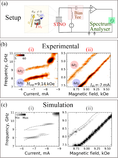
The studied STNO is a circular nanopillar with diameter of 250 nm consisting of (Cu60Py15Cu10Py4Au25) layers (numbers indicate the thickness in nanometers), fabricated by electron beam lithography, in which top and bottom Au and Cu electrodes were designed for microwave transport measurements. The STNO is excited by a negative dc current , corresponding to an electron flow from the thin to the thick magnetic layer, which allows us to observe STT-induced microwave generation. In the measurements presented below, a bias magnetic field in the range kOe was applied at from the sample normal (see Fig. 1(a)). This tilt is introduced in order to create a small misalignment between the static magnetizations of the layers, which is required for the appearance of resistance (and voltage) oscillations under almost circular magnetization precession; in the case of voltage oscillations vanish Hamadeh et al. (2012). However, this symmetry breaking also has significant consequences on the entire dynamics, as discussed in the following.
First, the bias current dependence of the voltage oscillation spectra under a constant magnetic field kOe is reported in Fig. 1(b). Within the current range from mA to mA, we observe two simultaneously auto-oscillating modes Sim , referred below as and , which are split by about 1.1 GHz. With a further current increase, the generation frequency exhibits a pronounced jump and generation becomes seemingly single-mode (the second mode is hardly detectable). Also, this jump is accompanied by a substantial power increase (see intensity scale and supplementary materials sup ). At even higher currents, the STNO generation demonstrates further frequency jumps and complex dynamics that are not considered here. Within the bimodal regime at mA, the frequencies of both modes demonstrate the same weak increase with the current amplitude, which is unexpected for almost perpendicularly magnetized STO, characterized by a strong nonlinear frequency shift Slavin and Tiberkevich (2009).
Fig. 1(c) presents the frequency evolution with the strength of a magnetic field under a constant dc current mA. The bimodal regime is robust to the field strength variation and is observed in the entire presented field range. The frequencies of both oscillation modes and vary almost linearly with the applied field; in almost perpendicularly magnetized STNO such dependence is not trivial as it may appear, indicating a significant nonlinear damping effect Slavin and Tiberkevich (2009). It is worth noting that in the case of perpendicular magnetization (), the generation characteristics of the STNO become fairly standard and none of the features described here indicating bimodal generation were observed Hamadeh et al. (2012); sup .
To get a deeper insight into the magnetization dynamics, micromagnetic simulations were performed using the FastMag software package Chang et al. (2011) that is based on the finite elements method (FEM). FastMag allows computing the full system including interactions between the reference and free layer via mutual spin transfer torque effects. FastMag also calculates the magneto-resistance response that can be directly compared to the experimental measurements. Material parameters were taken from the experimental study of passive dynamics (i.e., below auto-oscillation threshold) of the nanopillar Naletov et al. (2011) (see details in supplementary sup ). The FEM mesh edge length was chosen as 4 nm. The data evaluation of simulation was done through Aithericon Ait .
To excite the oscillation dynamics, a negative dc current was applied through the structure. The results of these micromagnetic simulations, shown in Fig. 1(d-e), reproduce the experimental measurements with a good qualitative and quantitative agreement, a clear indication that the advanced micromagnetic modeling is able to capture the features leading to the observed complex behavior. Reference simulations performed for the case show standard single-mode STNO behavior, in accordance with previous experimental study Hamadeh et al. (2012).
Next, we investigate spectra of the magnetization dynamics by evaluating the fast Fourier transform (FFT) of the circularly polarized transverse magnetization components emitted by the electrically driven STNO, where is the imaginary unit. In contrast to the resistance oscillation spectra, they demonstrate three peaks – an additional peak, referred to as , is visible below (Fig. 2). The frequency of the peaks satisfies the relation , which leads us to the assumption that four-magnon interaction between these modes, schematically shown in Fig. 2(b), is involved in STNO dynamics. Using a mesh resolved FFT, we obtain the spatial profiles of the excitations corresponding to these peaks.The main mode is a quasi-uniform mode characterized by respectively a radial index and an azimuthal index , which we label mode. This mode can be identified as the lowest-frequency mode of the isolated free layer. The peak at is the azimuthal mode, also mostly localized within the free layer. The excitation at resembles the azimuthal mode. However, in contrast to other excitations, this mode has comparable oscillation amplitude in both thin and thick STNO layers indicating a strong hybridization.
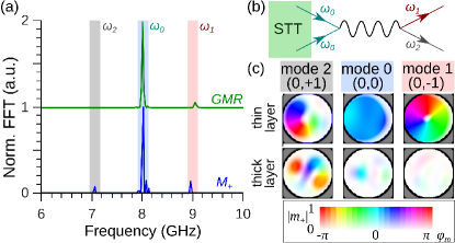
To elucidate the nature of the signal at , we performed micromagnetic simulations of the STNO modes in the passive regime (no dc current) sup . We found that in our device, the azimuthal eigenmodes of the thick layer are located below the fundamental mode of the thin layer (because of different saturation magnetization, see supplement) and these modes experience strong hybridization so that the oscillation amplitude is comparable in both layers (Fig. 3(b)). The last fact explains why the mode at is not visible in GMR spectra: the relative angle between the layers magnetizations is only weakly changed when it is excited. Thus, we attribute the multimode generation to a four-magnon process involving the fundamental mode (0,0) of the thin layer, the azimuthal mode of the thin layer and the mode of the thick layer that is strongly hybridized to the thin layer. This process satisfies the momentum conservation rule and the mode eigenfrequencies are reasonably close to the energy conservation rule . An additional check that the thick layer mode is involved in the multimode generation was made by simulating the active STNO with a drastically increased local field in the thick layer. In this case, the thick layer modes are shifted to much higher frequencies and the above-mentioned four-magnon process becomes impossible. Indeed, no multimode generation was observed in this case. In the reference case of a perpendicular field, the thick layer modes shift to lower frequencies and thus experience much less hybridization (Fig. 3(a)), which is crucial for the multimode generation as discussed below.

In the following, we consider an analytical model to describe the dynamics of STNO modes including parametric coupling. As before, we denote the fundamental mode as mode “0” having the amplitude , the mode of the thin layer and thick layer mode as modes 1 and 2, respectively, and consider dynamics of only these three modes. The mentioned four-magnon process is described by the term in the Hamiltonian of the system. Taking it into account, the dynamics of the coupled modes is described by equations
| (1) |
Here, an overdot denotes time derivative, , and are frequency and total damping of -th mode accounting for nonlinear contributions. In a general case, “total” frequency includes linear eigenfrequency, self and cross-nonlinear shifts from all modes: . The total damping accounts for nonlinear changes of both the damping and the STT anti-damping torque Slavin and Tiberkevich (2009): , where is the linear Gilbert damping and is the STT efficiency and is the nonlinear coefficients (see supplement).
Since the energy of mode 2 is more concentrated in the thick layer, while modes 0 and 1 are concentrated in the thin one, we neglect all related frequency and damping cross shifts, such as , , etc. Only for STT term (), such simplification is not appropriate since it is inversely proportional to the layer thickness, so the thin layer contribution to the total STT could be dominant even for mode 2. Linear frequencies for the model were extracted from micromagnetic data and nonlinear coefficients were estimated using the vector Hamiltonian formalism Tyberkevych et al. (2020); Verba et al. (2021), as described in Supplementary materials sup .
When the current increases, mode 0 first turns to the self-oscillation regime; this happens at (corresponding to -6 mA in the experiment). Formal thresholds of “isolated” modes 1 and 2 are larger, but competition for common STT pumping prohibits excitation of higher-order modes above their formal thresholds in the absence of other coupling Slobodianiuk (2014), and the only source for their excitation is the parametric instability of the mode 0. Then, assuming negligible amplitudes of the modes 1 and 2, we can calculate the “virtual” amplitude of mode 0 above the threshold in the absence of other modes, Slavin and Tiberkevich (2009), and the threshold amplitude of mode 0, above which parametric instability develops, Verba et al. (2021)
| (2) |
Here, the nonlinear frequency and the damping are calculated for the free-running amplitude of mode 0 at a given current and vanishing amplitudes of other modes. If , then the parametric instability occurs and modes 1 and 2 are excited.
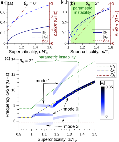
Dependencies of the isolated free-running amplitude and the parametric instability threshold are shown in Fig. 4(a,b). In the case of , the threshold is overcome in a certain range of currents, and a three-mode generation is expected. In contrast, in the reference case of a perpendicular field, the instability threshold is never overcome, and single-mode generation is expected. There are two reasons for this difference. The first one is the larger detuning from exact parametric resonance (see Fig. 4(a,b)) because of the different positions of the thick layer eigenmodes. However, this difference is not drastic and the second reason, namely the significantly (threefold) reduced parametric coupling also plays a crucial role. The latter is a result of the much lower hybridization of the modes, which is clear from the comparison of the oscillation amplitude in the thin layer at the position of mode of the thick layer in Fig. 3 (see calculation details in supplementary materials sup ). The same reason determines the explanation for the observation of this particular pair of parametric modes at . Another pair, which also satisfies the momentum conservation ( thick layer mode and thin layer mode), exhibits smaller parametric coupling because of lower hybridization of the thick layer mode (Fig. 3(b)).
Finally, we numerically integrate Eqs. 1 and present the stationary mode frequencies and amplitudes in Fig. 4(c). Starting from the threshold , the amplitude and frequency of the mode 0 increase and reach the parametric instability threshold (). Above this instability threshold, all three modes are excited and their frequencies are almost frozen (a feature that could be interesting for certain applications). In this regime, the parametric process dominates and the modes have stationary amplitudes that almost satisfy the parametric resonance condition . Above this generation regime cannot be sustained anymore, and we observed an abrupt jump of the mode frequencies and amplitudes as discerned in the experiment (see Fig. 1(b)). Mode 0 acquires an amplitude and a frequency that are close to the ones in the absence of parametric pumping, while modes 1 and 2 oscillate far from their “nonlinear eigenfrequencies” (i.e., the parametric process becomes strongly nonresonant). Their amplitudes decrease up to the current , above which the instability threshold becomes too high and the STNO returns to single-mode regime. Within the multimode generation range, the amplitude of parametric mode 1 is evidently larger than of the mode 2. This can be attributed to the substantially larger total damping rate of the mode 2. This circumstance also complicates the experimental observation of mode 2.
Overall, the model results are very similar to experimental observations. The finite range of multimode generation, the small (vanishing) frequency slope, the almost constant oscillation amplitude in the multimode regime, and the frequency jump are all observed in experiment. There is a quantitative difference in mode oscillation frequencies, which is on account of (i) the approximate calculation of nonlinear coefficients, particularly the phenomenological coefficient of nonlinear damping, and (ii) neglecting of the Oersted fields in the model that, according to experimental measurements below the threshold, result in the mode frequency increase about , almost the same for different modes.
To conclude, we found by experiment a regime of simultaneous multimode microwave emission by a nanopillar-based STO. The physical process behind this is a second-order parametric instability between a pair of radially symmetric magnon modes and a pair of opposite azimuthal index modes, without any spatio-temporal overlap. The process, however, satisfies the constraint of both angular momentum and energy conservation through the hybridization of eigenmodes between the thin and the thick layer. This co-generation has the additional feature of being incommensurable. The splitting between modes can thus be tuned by changing the characteristics of the nano-pillar such as its diameter. A future work direction will be to exploit non-uniform magnetic textures as a means to control continuously the splitting by an external bias parameter, such as the magnetic field. A particularly promising candidate is the vortex, where the splitting between the has been shown to vary strongly as a function of . We believe that the simultaneous self-generation of multiple frequencies in dc-driven spintronic elements has large potential for applications using frequency multiplexing techniques in neuromorphic and wave-based approaches.
Acknowledgements.
This work has been supported by the European Research Council within the Starting Grant No. 101042439 "CoSpiN" and by the Deutsche Forschungsgemeinschaft (DFG, German Research Foundation) - TRR 173 - 268565370" (project B01) and by the French Grants ANR-21-CE24-0031 Harmony and the EU-project H2020-2020-FETOPEN k-NET-899646 and by the National Academy of Sciences of Ukraine, project #0122U002462 and the project PRIN 2020LWPKH7 funded by the Italian Ministry of University and Research.References
- Slonczewski (1996) J. C. Slonczewski, J. Magn. Magn. Mater. 159, L1 (1996).
- Berger (1996) L. Berger, Phys. Rev. B 54, 9353 (1996).
- Wolf et al. (2001) S. Wolf, D. Awschalom, R. Buhrman, J. Daughton, v. S. von Molnár, M. Roukes, A. Y. Chtchelkanova, and D. Treger, science 294, 1488 (2001).
- Thomas et al. (2014) L. Thomas, G. Jan, J. Zhu, H. Liu, Y.-J. Lee, S. Le, R.-Y. Tong, K. Pi, Y.-J. Wang, D. Shen, et al., J. Appl. Phys. 115, 172615 (2014).
- Hirohata et al. (2020) A. Hirohata, K. Yamada, Y. Nakatani, I.-L. Prejbeanu, B. Diény, P. Pirro, and B. Hillebrands, J. Magn. Magn. Mater. 509, 166711 (2020).
- Kiselev et al. (2003) S. I. Kiselev, J. C. Sankey, I. N. Krivorotov, N. C. Emley, R. J. Schoelkopf, R. A. Buhrman, and D. C. Ralph, Nature 425, 380 (2003).
- Mistral et al. (2006) Q. Mistral, J.-V. Kim, T. Devolder, P. Crozat, C. Chappert, J. A. Katine, M. J. Carey, and K. Ito, Appl. Phys. Lett. 88, 192507 (2006).
- Houssameddine et al. (2008) D. Houssameddine, S. Florez, J. Katine, J.-P. Michel, U. Ebels, D. Mauri, O. Ozatay, B. Delaet, B. Viala, L. Folks, et al., Appl. Phys. Lett. 93, 022505 (2008).
- Mistral et al. (2008) Q. Mistral, M. van Kampen, G. Hrkac, J.-V. Kim, T. Devolder, P. Crozat, C. Chappert, L. Lagae, and T. Schrefl, Phys. Rev. Lett. 100, 257201 (2008).
- Zeng et al. (2013) Z. Zeng, G. Finocchio, and H. Jiang, Nanoscale 5, 2219 (2013).
- Bonetti et al. (2009) S. Bonetti, P. Muduli, F. Mancoff, and J. Åkerman, Appl. Phys. Lett. 94, 102507 (2009).
- Prokopenko et al. (2012) O. V. Prokopenko, E. Bankowski, T. Meitzler, V. S. Tiberkevich, and A. N. Slavin, IEEE Trans. Magn. 48, 3807 (2012).
- Rippard et al. (2004) W. H. Rippard, M. R. Pufall, S. Kaka, S. E. Russek, and T. J. Silva, Phys. Rev. Lett. 92, 027201 (2004).
- Grimaldi et al. (2014) E. Grimaldi, R. Lebrun, A. Jenkins, A. Dussaux, J. Grollier, V. Cros, A. Fert, H. Kubota, K. Yakushiji, A. Fukushima, et al., in 2014 IEEE International Frequency Control Symposium (FCS) (IEEE, 2014) pp. 1–6.
- Louis et al. (2017) S. Louis, V. Tyberkevych, J. Li, I. Lisenkov, R. Khymyn, E. Bankowski, T. Meitzler, I. Krivorotov, and A. Slavin, IEEE Trans. Magn. 53, 1 (2017).
- Litvinenko et al. (2020) A. Litvinenko, V. Iurchuk, P. Sethi, S. Louis, V. Tyberkevych, J. Li, A. Jenkins, R. Ferreira, B. Dieny, A. Slavin, et al., Nano Lett. 20, 6104 (2020).
- Skowroński et al. (2019) W. Skowroński, J. Chęciński, S. Ziętek, K. Yakushiji, and S. Yuasa, Sci. Rep. 9, 1 (2019).
- Madami et al. (2011) M. Madami, S. Bonetti, G. Consolo, S. Tacchi, G. Carlotti, G. Gubbiotti, F. Mancoff, M. A. Yar, and J. Åkerman, Nature nanotechnology 6, 635 (2011).
- Torrejon et al. (2017) J. Torrejon, M. Riou, F. A. Araujo, S. Tsunegi, G. Khalsa, D. Querlioz, P. Bortolotti, V. Cros, K. Yakushiji, A. Fukushima, et al., Nature 547, 428 (2017).
- Grollier et al. (2016) J. Grollier, D. Querlioz, and M. D. Stiles, Proceedings of the IEEE 104, 2024 (2016).
- Riou et al. (2019) M. Riou, J. Torrejon, B. Garitaine, F. A. Araujo, P. Bortolotti, V. Cros, S. Tsunegi, K. Yakushiji, A. Fukushima, H. Kubota, et al., Phys. Rev. Applied 12, 024049 (2019).
- Slavin and Tiberkevich (2009) A. Slavin and V. Tiberkevich, IEEE Trans. Magn. 45, 1875 (2009).
- Eklund et al. (2013) A. Eklund, S. Sani, S. Mohseni, J. Persson, B. Malm, and J. Akerman, in Noise and Fluctuations (ICNF), 2013 22nd International Conference on (doi=10.1109/ICNF.2013.6578965, 2013) pp. 1–4.
- Heinonen et al. (2013) O. Heinonen, P. Muduli, E. Iacocca, and J. Akerman, IEEE Trans. Magn. 49, 4398 (2013).
- Iacocca et al. (2014) E. Iacocca, O. Heinonen, P. K. Muduli, and J. Åkerman, Phys. Rev. B 89, 054402 (2014).
- Slobodianiuk (2014) D. V. Slobodianiuk, Cond. Matter Phys. 17, 13801 (2014).
- Chen et al. (2022) L. Chen, W. Wang, X. Zhan, K. Zhou, Z. Gao, L. Liang, T. Zhou, Y. Du, and R. Liu, Phys. Rev. B 105, 104413 (2022).
- Yang et al. (2015) L. Yang, R. Verba, V. Tiberkevich, T. Schneider, A. Smith, Z. Duan, B. Youngblood, K. Lenz, J. Lindner, A. N. Slavin, and I. N. Krivorotov, Sci. Rep. 5, 16942 (2015).
- L’vov (1994) V. S. L’vov, Wave Turbulence under Parametric Excitation (Springer-Verlag, New York, 1994).
- Suhl (1957) H. Suhl, Journal of Physics and Chemistry of Solids 1, 209 (1957).
- Pirro et al. (2021) P. Pirro, V. I. Vasyuchka, A. A. Serga, and B. Hillebrands, Nature Reviews Materials 6, 1114–1135 (2021).
- Pirro et al. (2014) P. Pirro, T. Sebastian, T. Brächer, A. A. Serga, T. Kubota, H. Naganuma, M. Oogane, Y. Ando, and B. Hillebrands, Physical Review Letters 113, 227601 (2014).
- Hamadeh et al. (2012) A. Hamadeh, G. De Loubens, V. Naletov, J. Grollier, C. Ulysse, V. Cros, and O. Klein, Phys. Rev. B 85, 140408 (2012).
- (34) We have checked it experimentally by performing a synchronization experiment. It showed that both and are locked together when an external oscillation is additionally applied at either or . We interpret this as a proof of the simultaneity of the emission.
- (35) Supplementary materials are located at … They contain: (i) description of micromagnetic simulations, (ii) current dependence of generation power for perpendicular and tilted fields, and (iii) details of the parameters calculations for theoretical model.
- Chang et al. (2011) R. Chang, S. Li, M. Lubarda, B. Livshitz, and V. Lomakin, J. Appl. Phys. 110, 039907 (2011).
- Naletov et al. (2011) V. V. Naletov, G. De Loubens, G. Albuquerque, S. Borlenghi, V. Cros, G. Faini, J. Grollier, H. Hurdequint, N. Locatelli, B. Pigeau, et al., Phys. Rev. B 84, 224423 (2011).
- (38) Www.aithericon.com.
- Tyberkevych et al. (2020) V. Tyberkevych, A. Slavin, P. Artemchuk, and G. Rowlands, “Vector Hamiltonian Formalism for Nonlinear Magnetization Dynamics,” (2020), arXiv:2011.13562 [cond-mat.mtrl-sci].
- Verba et al. (2021) R. Verba, L. Körber, K. Schultheiss, H. Schultheiss, V. Tiberkevich, and A. Slavin, Phys. Rev. B 103, 014413 (2021).