Observation of uniaxial strain tuned spin cycloid in a freestanding BiFeO3 film
Abstract
Non-collinear spin order that breaks space inversion symmetry and allows efficient electric-field control of magnetism makes BiFeO3 a promising candidate for applications in low-power spintronic devices[1, 2, 3, 4]. Epitaxial strain effects have been intensively studied and exhibit significant modulation of the magnetic order in BiFeO3[5, 6], but tuning its spin structure with continuously varied uniaxial strain is still lacking up to date. Here, we apply in situ uniaxial strain to a freestanding BiFeO3 film and use scanning NV microscope to image the nanoscale magnetic order in real-space. The strain is continuously increased from 0% to 1.5% and four images under different strains are acquired during this period. The images show that the spin cycloid tilts by when strain approaches 1.5%. A first principle calculation has been processed to show that the tilting is energetically favorable under such strain. Our in situ strain applying method in combination with scanning NV microscope real-space imaging ability paves a new way in studying the coupling between magnetic order and strain in BiFeO3 films.
Antiferromagnetic material is robust against external magnetic field disturb, has super-fast spin dynamics and possesses large magneto-transport effects. Due to the merits above, antiferromagnetic materials have important application in spintronics and other magnetism-based techniques [7]. Although it is a promising material, because of its anti-parallel spin configuration which leads to zero stray-field, antiferromagnetic material cannot be well studied by normal near-field imaging techniques [8]. Non-collinear antiferromagnetic perovskite compound bismuth ferrite (BiFeO3, BFO) is the only magnetoelectric multiferroic material under room temperature. Since the non-collinear spin cycloid breaks spatial inversion symmetry, it can be controlled by external electric field and thus costs much less energy comparing to ordinary ferromagnetic devices [8]. BFO owns spin cycloid because of the Dzyaloshinskii–Moriya interaction (DMI), such cycloid induces an effective magnetization which is too weak to detect with normal methods such as MFM[9] and PEEM[10]. At the same time, since BFO has eV bandgap[11], sp-STM also lacks the ability to perform imaging. Scanning NV microscopy (SNVM) is an emergent real-space scanning method with nanoscale spatial resolution and magnetic sensitivity[12, 13]. People have utilized SNVM to study the magnetic structure of BFO epitaxial films at nanoscale [8, 6, 14].
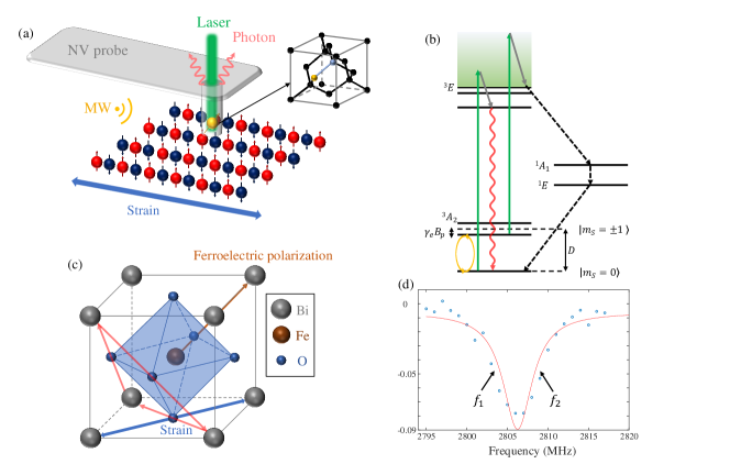
BFO is a kind of perovskite compound while fulfills noncentrosymmetric rhombohedral space group[16]. The structure of BFO is shown in figure 1(c), for the sake of brevity, we adopt pseudo-cubic unit cell. In each unit cell, bismuth atoms are at eight corners, while at the center lays the iron atom contained by an octahedron constructed by six oxygen atoms. The ferroelectric Curie temperature of BFO is [17, 18], below which the ferroelectric polarization is as high as 100 C/cm2 in high quality grown films [19, 20]. The antiferromagnetic order of BFO is characterized as G-type, with Néel temperature [21]. 3d electrons of Fe3+ are the origin of magnetism of BFO, while ferroelectricity and antiferrodistortive break the spatial inversion symmetry which gives rise to a DMI. This interaction leads to a small canting angle between neighbor spins and this produces an effective spin density as large as 0.02 per unit cell [22, 8]. Under proper conditions, spin distribution in BFO will turn cycloidal, which is an incommensurable periodic order. A cycloidal order can be described by a wave vector , as indicated in figure 1(c). The magnetic order of BFO is decided by external field, strain, temperature, size and more factors, while the effect of strain has been intensively studied[5, 6, 23, 24, 25, 26]. Previous works utilized different substrates to adjust the epitaxial strain in BFO and found two types of cycloidal order[6, 5]. While these researches provide the phase diagram of BFO magnetic order with respect to epitaxial strain, they are not able to impose adjustable strain to BFO in situ and this leaves the mechanism of BFO magnetic transformation at critical point an outstanding open question [5, 6, 16]. Besides, previous researches mainly focus on biaxial strain while real-space imaging of magnetic structure under uniaxial strain has not yet been performed.
In this work, we adopt a new method base on molecular beam epitaxy (MBE) to prepare freestanding BFO film[20, 27]. A 75-unit-cell-thick BFO (001) film is prepared and transferred to organic substrate Polyethylenenaphthalate(PEN) while epoxy is used as the glue to conduct strain to the BFO film. During experiments, uniaxial, continuous and in situ strain is imposed on the BFO film by means of mechanically stretching the PEN substrate [28, 29]. In principle, this method is able to impose arbitrary in-plane tensile strain on the film, while in this work the strain principal axis deviates from by . Such strain breaks the intrinsic symmetry of BFO and provide a way to tune the spin cycloid’s direction continuously. A home-built SNVM is used to perform nanoscale magnetic imaging of its stray field. By using this method, we find that the direction of the cycloidal order is modulated by the uniaxial strain which confirms to a first principle calculation. This phenomenon may help people understanding the transition mechanism of magnetic order under strain[5, 16] whilst the freestanding film based method can be used in strain-based spintronics, new heterostructure devices and other new multifunctional devices [20, 29, 28]. Our new freestanding film based method in combination with SNVM real-space imaging ability paves a new way to study strain-magnetism coupling in antiferromagnetic materials.
SNVM has been widely used in condensed matter physics[30, 31, 32, 33, 34, 35], here we apply SNVM to the freestanding BFO film to acquire stray field distribution near the surface. The structure of our SNVM setup is demonstrated in figure 1(a). The Nitrogen-Vacancy color center (NV center) in diamond is a point defect shown in the inset. It is formed by a nitrogen atom (orange ball in the inset) and an adjacent vacancy (blue ball in the inset) in diamond lattice [36]. As shown in figure 1(b), the NV center is pumped from ground state () into phonon sideband by 532 nm green laser (green arrows) and relaxes into excited state () with angular momentum conserved (grey arrows). emits photons (wavy red arrow) during the transition to ground state and the photons are finally detected by a single photon detector. evolves into ground state through meta-stable states () with no detectable photon emitted (black dotted line arrows). The degeneracy of is lifted by Zeeman splitting generated by external magnetic field () and resonant microwave (MW, orange circled arrow) is applied by a copper micro-antenna to selectively excite one of the spin states. By using the photon count rate’s difference between and , it is straight forward to readout the NV center’s spin state.
In our experiment, by applying green laser and MW simultaneously and readout the photon counts, we utilize the Continuous Wave Optically Detected Magnetic Resonance (CW-ODMR) spectrum. In order to accelerate the imaging speed, we adopt the dual-iso-B protocol shown in figure 1(d) [8]. Applying this protocol, by sampling at two MW frequencies, we are able to calculate the projection of the stray field to the NV axis[15]. By scanning across a magnetic film edge, we determine that the distance from the NV center to sample surfaces is 78.51.8 nm (with 95% confidence) [37, 38, 15].
Beforehand, a piezoelectric force microscope (PFM) is utilized to electrically polarize an area of the BFO film to [15]. During the experiment, a uniaxial strain is applied to the BFO film via the PEN substrate. By employing X-ray diffraction (XRD) after the experiment, we are able to calibrate strains under which the images are acquired [15].
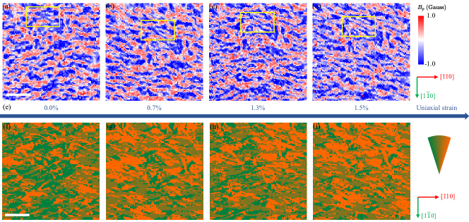
SNVM imaging is implemented under four different strains: , the results are shown in figure 2. The principal axis of strain deviates from high symmetry direction by 4.7∘, which breaks symmetry and leads to cycloid tilting. From the real-space imaging one can find that although the coherence length is relatively small, the sample does possess local cycloidal order, which is modulated by the increasing uniaxial strain. We attribute this small coherence length to in-homogeneous strain gradient introduced by epitaxial interface [39]. Be aware that we are using a novel, organic and soft substrate in combination with a freestanding film to realize in situ strain tuning. Without rigid constraint from crystal substrates, freestanding films possess intrinsic unevenness, which may also lead to the small coherence length [28]. Despite the relatively small coherence length, spin cycloid’s variation during the increasing of strain is rather distinct. We calculate the direction of cycloidal wave vector by minimizing variances on segments parallel to different directions and apply region growing algorithm to the results to acquire wave vector direction domain image plotted in figure 2(f-i). It is evident that during the application of strain, the wave vector tilts away from .
Be aware that the applied strain also modulates local distribution of the magnetic order, there are plural non-trivial local transitions while the applied strain increases. For example, by retracing with respect to tomography markers and magnetic patterns, we are able to determine that the boxed areas in figure 2 are at the same spot[40]. Two different ordered areas at this spot merge into one when strain approaches 1.5%. This phenomenon is interpreted as the release of local strain gradient under external strain.
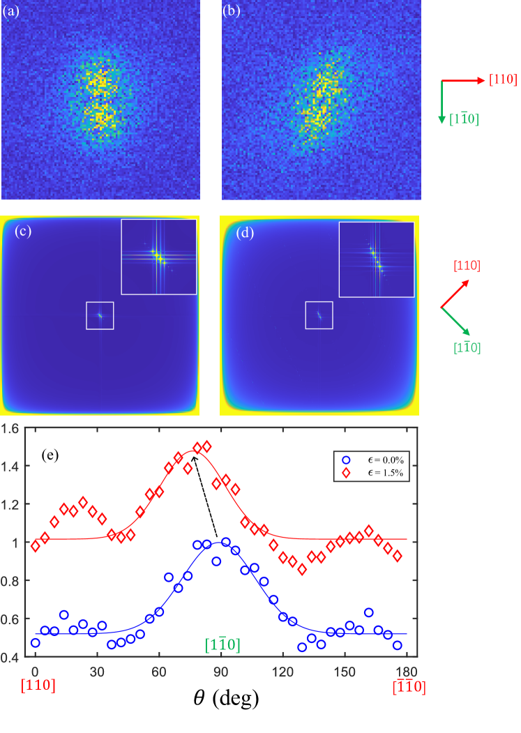
We have acquired a qualitative result that during the application of strain, the wave vector tilts away from . In order to obtain quantitative relation between the tilting angle and strain, we apply Fourier transformation (FT) to the initial and final real-space scanning results to obtain the wave vector distribution in reciprocal space, which is shown in figure 3(a,b). It is distinctive that the wave vector tilts away from while the strain increases, this confirms to our qualitative result from the real-space imaging. We accounts the wave vector with respect to its azimuth angle, the result is displayed in figure 3(e). One can find that, while the strain increases, the wave vector tilts by .
In order to explain the wave vector’s tilting under strain, first-principle-based simulations are performed using magnetic effective Hamiltonian [41, 15] with the magnetic exchange interaction coefficients evaluated from the four-state mapping approach [42].
The uniaxial strain is modeled by stretching the cell along the direction slightly deviates from pseudo-cubic [110] direction by 4.7 ∘. The strain is chosen to be 1.5% according to XRD calibration, and an estimated Poisson’s ratio of about 0.24 calculated via XRD data is also considered [15]. Note that due to the symmetry broken caused by strain, the symmetry of the system is reduced from space group to , and all the sixfold-degenerate pair in the structure[41] are no longer degenerate. The calculated exchange coefficients are shown in the Supplemental Information [15].
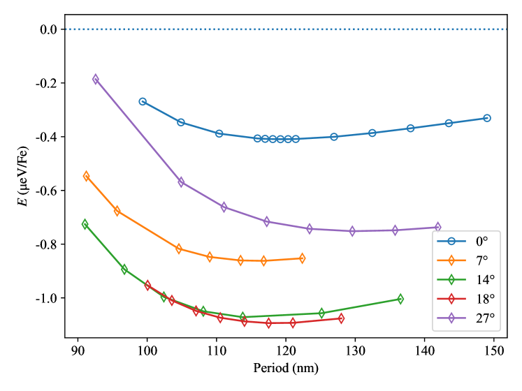
Parallel tempering Monte Carlo (PTMC) simulations [43, 44] are performed to solve the magnetic effective Hamiltonian. A large supercell of is used study the cycloidal phase, where a is along the pseudo-cubic direction, b is along the pseudo-cubic direction, and c is along the pseudo-cubic direction. To study the stable period of the cycloidal phase, energy per Fe atom is calculated as a function of cycloidal period, as shown in Fig. 4. This energy-versus-period curve shows a minimum at 119 nm, which is similar to that in the phase [41].
To study cycloid which deviates the direction, several oblique supercells are constructed. The supercells slightly tilting about c direction were used. The angle between the lattice vector and the pseudo-cubic direction is used to define the oblique angle of cycloid. For example, one of the oblique supercells used in this work is defined by where and are the vectors we used to define our relaxed BFO lattices which are close to the pseudo-cubic and direction, respectively. The oblique angle of such cell is then the angle between the and , that is approximately 7∘. Figure 4 shows the calculated energy of supercells with different oblique angles as functions of cycloidal period. The energies of supercells with non-zero oblique angles are lower than that of supercells without oblique angle, indicating the oblique supercells are more energetically favorable. Moreover, with the increasing of the oblique angle from 0∘, the energy shows a nonmonotonic behavior with respect to the oblique angle, with a minimum around 18∘. Such value is in in very well consistent with the measured value 12.6∘ (refer to figure 3(e)).
To confirm the cycloids in the rotated supercells do propagate along a direction deviates from , FT is also performed to the PTMC simulation results [15]. Figure 3 (d) shows the spectrum of one supercell with oblique angle 18 ∘ after the FT, showing a peak at the coordinate , which is away from the pseudo-cubic direction by 18∘ (calculated from ). On the other hand, figure 3 (c) shows such spectrum on a supercell without oblique angle of non-stretched cell ( phase as in Ref. [41]), showing a peak at the coordinate , which is exactly along the pseudo-cubic direction. The deviation of such peak from pseudo-cubic direction definitely confirms that the cycloids in oblique cells do propagate along a direction deviates from direction. We thus conclude that such deviation of the cycloid is energetically more favorable that without deviation.
Note that we also performed above analysis on BFO at tensile strain of 0.5% along exactly the pseudo-cubic [110] direction without oblique angle, and found the cycloid propagates along the pseudo-cubic (i.e. with oblique angle 0∘) is the most energetically favored phase. Such fact indicates that the deviation of the cycloid propagation originates from the symmetry broken caused by the uniaxial strain colorred with an oblique angle.
In summary, we apply contineous in situ uniaxial strain to freestanding BFO films and scan the magnetic stray field near surface with SNVM. A modulation of direction of the magnetic order is found and a first principle calculation is conducted. The first principle calculation result confirms that the strain induced magnetic effective Hamiltonian evolution is responsible for the rotation of magnetic order. This result is helpful for people to understand the mechanism of magnetic order transformation under strains. Besides, our freestanding-film-based in situ strain applying method paves a new way to study the coupling between strain and magnetism in antiferromagnetic materials. With some slight improvements, it is possible to conduct arbitrary in-plane tensile strain to the sample, which provides people with higher degrees of freedom to study the mechanism of magnetic order transition under strains.
Acknowledgements.
This work was supported by the National Natural Science Foundation of China (grant nos. 81788101, T2125011, No.12104447), the National Key R&D Program of China (grant nos. 2018YFA0306600 and 2021YFA1400400), the CAS (grant nos. XDC07000000, GJJSTD20200001, QYZDY-SSW-SLH004, Y201984, YSBR-068), Innovation Program for Quantum Science and Technology (Grant No. 2021ZD0302200, 2021ZD0303204), the Anhui Initiative in Quantum Information Technologies (grant no. AHY050000), the Natural Science Foundation of Jiangsu Province (grant No. BK20200262), Hefei Comprehensive National Science Center, China Postdoctoral Science Foundation (Grant No. 2020M671858) and the Fundamental Research Funds for the Central Universities. We are grateful to the HPCC resources of Nanjing University for the calculations. The NV scanning probe was provided by CIQTEK and the assembling was completed by Ruige Shao. This work was partially carried out at the USTC Center for Micro and Nanoscale Research and Fabrication.References
- [1] Kimura, T. et al. Magnetic control of ferroelectric polarization. Nature 426, 55–58 (2003).
- [2] Lottermoser, T. et al. Magnetic phase control by an electric field. Nature 430, 541–544 (2004).
- [3] Cheong, S.-W. & Mostovoy, M. Multiferroics: A magnetic twist for ferroelectricity. Nature Materials 6, 13–20 (2007).
- [4] Heron, J. T. et al. Deterministic switching of ferromagnetism at room temperature using an electric field. Nature 516, 370–373 (2014).
- [5] Sando, D. et al. Crafting the magnonic and spintronic response of BiFeO3 films by epitaxial strain. Nature Materials 12, 641–646 (2013).
- [6] Haykal, A. et al. Antiferromagnetic textures in BiFeO 3 controlled by strain and electric field. Nature Communications 11, 1704 (2020).
- [7] Baltz, V. et al. Antiferromagnetic spintronics. Reviews of Modern Physics 90, 015005 (2018).
- [8] Gross, I. et al. Real-space imaging of non-collinear antiferromagnetic order with a single-spin magnetometer. Nature 549, 252 (2017).
- [9] Hartmann, U. Magnetic Force Microscopy. Annual Review of Materials Science 29, 53–87 (1999).
- [10] Locatelli, A. & Bauer, E. Recent advances in chemical and magnetic imaging of surfaces and interfaces by XPEEM. Journal of Physics: Condensed Matter 20, 093002 (2008).
- [11] Sando, D. et al. Large elasto-optic effect and reversible electrochromism in multiferroic BiFeO3. Nature Communications 7, 1–7 (2016).
- [12] Taylor, J. M. et al. High-sensitivity diamond magnetometer with nanoscale resolution. Nature Physics 4, 810–816 (2008).
- [13] Maletinsky, P. et al. A robust scanning diamond sensor for nanoscale imaging with single nitrogen-vacancy centres. Nature Nanotechnology 7, 320–324 (2012).
- [14] Chauleau, J.-Y. et al. Electric and antiferromagnetic chiral textures at multiferroic domain walls. Nature Materials 19, 386–390 (2020).
- [15] Please refer to supplementary information.
- [16] Burns, S. R., Paull, O., Juraszek, J., Nagarajan, V. & Sando, D. The Experimentalist’s Guide to the Cycloid, or Noncollinear Antiferromagnetism in Epitaxial BiFeO3. Advanced Materials 32, 2003711 (2020).
- [17] Kaczmarek, W., Paja̧k, Z. & Połomska, M. Differential thermal analysis of phase transitions in (Bi1-xLax)FeO3 solid solution. Solid State Communications 17, 807–810 (1975).
- [18] Neaton, J. B., Ederer, C., Waghmare, U. V., Spaldin, N. A. & Rabe, K. M. First-principles study of spontaneous polarization in multiferroic BiFeO3. Physical Review B 71, 014113 (2005).
- [19] Wang, J. et al. Epitaxial BiFeO3 Multiferroic Thin Film Heterostructures. Science 299, 1719–1722 (2003).
- [20] Ji, D. et al. Freestanding crystalline oxide perovskites down to the monolayer limit. Nature 570, 87–90 (2019).
- [21] Kiselev, S. V., Ozerov, R. P. & Zhdanov, G. S. Detection of Magnetic Order in Ferroelectric BiFeO3 by Neutron Diffraction. Soviet Physics Doklady 7, 742 (1963).
- [22] Albrecht, D. et al. Ferromagnetism in multiferroic BiFeO3 films: A first-principles-based study. Physical Review B 81, 140401 (2010).
- [23] Waterfield Price, N. et al. Strain Engineering a Multiferroic Monodomain in Thin-Film BiFeO3. Physical Review Applied 11, 024035 (2019).
- [24] Sando, D. et al. A magnetic phase diagram for nanoscale epitaxial BiFeO3 films. Applied Physics Reviews 6, 041404 (2019).
- [25] Sando, D. et al. Influence of flexoelectricity on the spin cycloid in (110)-oriented BiFeO3 films. Physical Review Materials 3, 104404 (2019).
- [26] Chen, Z. et al. Complex strain evolution of polar and magnetic order in multiferroic BiFeO3 thin films. Nature Communications 9, 3764 (2018).
- [27] Lu, D. et al. Synthesis of freestanding single-crystal perovskite films and heterostructures by etching of sacrificial water-soluble layers. Nature Materials 15, 1255–1260 (2016).
- [28] Zang, Y. et al. Giant Thermal Transport Tuning at a Metal/Ferroelectric Interface. Advanced Materials 34, 2105778 (2022).
- [29] Han, L. et al. Giant Uniaxial Strain Ferroelectric Domain Tuning in Freestanding PbTiO3 Films. Advanced Materials Interfaces 7, 1901604 (2020).
- [30] Zhe Ding, Fazhan Shi & Jiangfeng Du. Nanoscale magnetic imaging based on quantum sensing with diamond and its applications to condensed matter physics. Physics 49, 359–372 (2020).
- [31] Casola, F., van der Sar, T. & Yacoby, A. Probing condensed matter physics with magnetometry based on nitrogen-vacancy centres in diamond. Nature Reviews Materials 3, 17088 (2018).
- [32] Tetienne, J.-P. et al. Nanoscale imaging and control of domain-wall hopping with a nitrogen-vacancy center microscope. Science 344, 1366–1369 (2014).
- [33] Pelliccione, M. et al. Scanned probe imaging of nanoscale magnetism at cryogenic temperatures with a single-spin quantum sensor. Nature Nanotechnology 11, 700–705 (2016).
- [34] Hedrich, N. et al. Nanoscale mechanics of antiferromagnetic domain walls. Nature Physics 1–4 (2021).
- [35] Ku, M. J. H. et al. Imaging viscous flow of the Dirac fluid in graphene. Nature 583, 537–541 (2020).
- [36] Doherty, M. W. et al. The nitrogen-vacancy colour centre in diamond. Physics Reports 528, 1–45 (2013). eprint 1302.3288.
- [37] Jenkins, A. et al. Single-spin sensing of domain-wall structure and dynamics in a thin-film skyrmion host. Physical Review Materials 3, 083801 (2019).
- [38] Tetienne, J.-P. et al. The nature of domain walls in ultrathin ferromagnets revealed by scanning nanomagnetometry. Nature Communications 6, 6733 (2015).
- [39] Sando, D. et al. Interfacial Strain Gradients Control Nanoscale Domain Morphology in Epitaxial BiFeO3 Multiferroic Films. Advanced Functional Materials 30, 2000343 (2020).
- [40] When we adjust strain, a movement at hundred micrometer scale is introduced by the strain applying positioner. A built–in optical microscope supplies tomography information to help reset the sample’s position. The limited spatial resolution of the optical microscope is the reason that the field of views under different strains slightly mismatch, though we could retrace common areas by referring to neighbor magnetic patterns.
- [41] Xu, C., Xu, B., Dupé, B. & Bellaiche, L. Magnetic interactions in : A first-principles study. Phys. Rev. B 99, 104420 (2019).
- [42] Xiang, H., Lee, C., Koo, H.-J., Gong, X. & Whangbo, M.-H. Magnetic properties and energy-mapping analysis. Dalton Trans. 42, 823–853 (2013).
- [43] Earl, D. J. & Deem, M. W. Parallel tempering: Theory, applications, and new perspectives. Phys. Chem. Chem. Phys. 7, 3910–3916 (2005).
- [44] Lou, F. et al. Pasp: Property analysis and simulation package for materials. The Journal of Chemical Physics 154, 114103 (2021).