ATHENA Detector Proposal
A Totally Hermetic Electron Nucleus Apparatus
proposed for IP6 at the Electron-Ion Collider
Abstract
ATHENA has been designed as a general purpose detector capable of delivering the full scientific scope of the Electron-Ion Collider. Careful technology choices provide fine tracking and momentum resolution, high performance electromagnetic and hadronic calorimetry, hadron identification over a wide kinematic range, and near-complete hermeticity.
This article describes the detector design and its expected performance in the most relevant physics channels. It includes an evaluation of detector technology choices, the technical challenges to realizing the detector and the R&D required to meet those challenges.
1 Introduction
The Electron-Ion Collider (EIC) will be the world’s first collider of polarized electrons with polarized protons and light nuclei. It will also be the world’s first collider of polarized electrons with heavy nuclei. Its purpose will be to explore the quark and gluon structure of protons and nuclei, elucidating the origins of nuclear spin and nuclear mass, and shedding light on emergent phenomena involving dense systems of gluons.
A large international scientific community has grown around the EIC since its inception. The EIC Users Group [eicug] was formed in 2016 to coordinate efforts toward developing the science case and detector concepts required to realize the facility. It currently represents more than 1300 scientists worldwide.
The EIC is to be built at the Brookhaven National Laboratory and will be hosted jointly by Brookhaven and the Thomas Jefferson National Accelerator Facility, bringing together two world class laboratories with long standing expertise in building hadron and electron beam accelerators. It will incorporate the existing Relativistic Heavy Ion Collider and will instrument two interactions points, designated IP6 and IP8, providing locations for two detectors.
On March 6, 2021, the two host laboratories issued a Call for Collaboration Proposals for Detectors at the EIC. The first detector is to be located at IP6 and falls within the scope of the Department of Energy (DoE) funded project. The call stipulated that the project detector should be based on the reference design developed by the EIC Users Group, which is described in a Yellow Report [AbdulKhalek:2021gbh] and was included in the EIC Conceptual Design Report (CDR) [EIC-CDR]. The project detector must satisfy all the science requirements of the DoE “mission need” statement that was informed by the EIC community White Paper [Accardi:2012qut] and the National Academies of Science (NAS) assessment of EIC science [NASRep:2018]. Proposals for a second detector, to be located at IP8, could be complementary in technology choices; optimized for particular areas of EIC science or address science beyond that described in the White Paper and NAS report.
In response to this call, a kick-off meeting was held on March 12-13, 2021, with the aim of forming a collaboration to design a novel, powerful, general-purpose detector that meets all the science requirements within the given cost envelope. Originally named EIC@IP6, this effort was joined by many EIC enthusiasts who had been instrumental in realizing the Yellow Report and the CDR, and who had been active participants in the preceding Generic Detector R&D Program [EIC-RD]. In the months that followed, this effort led to the formation of the ATHENA collaboration comprising 94 institutions from 13 countries, with 36% of participants from North America, 34% from Europe, and 30% from Asia. Design activities were organized around ten Working Groups (WGs). Six detector WGs were established focusing on different aspects of the design, and four physics WGs evaluated the detector performance against the science requirements. A separate software WG supported the development of realistic simulations of the detector design in concert with the detector WGs. A proposal committee formed of three subgroups: integration and global design, costing and editing; was charged to distil this work into a coherent detector proposal. This article presents the outcome of this combined effort, describing the design and performance of the proposed ATHENA detector.
1.1 EIC Physics Scope
The EIC will be a world-wide unique facility to address fundamental questions regarding visible matter in the universe. The EIC Yellow Report [AbdulKhalek:2021gbh] poses the overarching questions as follows:
-
•
How do the nucleonic properties such as mass and spin emerge from partons and their underlying interactions?
-
•
How are partons inside the nucleon distributed in both momentum and position space?
-
•
How do color-charged quarks and gluons, and jets, interact with a nuclear medium? How do the confined hadronic states emerge from these quarks and gluons? How do the quark-gluon interactions create nuclear binding?
-
•
How does a dense nuclear environment affect the dynamics of quarks and gluons, their correlations, and their interactions? What happens to the gluon density in nuclei? Does it saturate at high energy, giving rise to gluonic matter or a gluonic phase with universal properties in all nuclei and even in nucleons?
| Neutral-current Inclusive DIS: e+p /A for this process, it is essential to detect the scattered electron, , with high precision. All other final state particles () are ignored. The scattered electron is critical for all processes to determine the event kinematics. The key kinematic variable in this process are and where is the momentum fraction of the quark (w.r.t. the nucleon) on which the photon scatters. is the squared momentum transfer to the electron , equal to the virtuality of the exchanged photon. Large values of provide a hard scale to the process, which allows one to resolve quarks and gluons in the proton. |
![[Uncaptioned image]](/html/2210.09048/assets/x1.png)
|
| Charged-current Inclusive DIS: e+p /A at high enough momentum transfer , the electron-quark interaction is mediated by the exchange of a gauge boson instead of the virtual photon. In this case the event kinematic cannot be reconstructed from the scattered electron, but needs to be reconstructed from the final state particles. |
![[Uncaptioned image]](/html/2210.09048/assets/x2.png)
|
| Semi-inclusive DIS: e+p /A , which requires measurement of at least one identified hadron in coincidence with the scattered electron. |
![[Uncaptioned image]](/html/2210.09048/assets/x3.png)
|
| Exclusive DIS: e+p /A , which require the measurement of all particles in the event with high precision. A key kinematic variable for this process is , the invariant square of the momentum transfer of the scattered proton or ion, which is crucial for all parton imaging studies. |
![[Uncaptioned image]](/html/2210.09048/assets/x4.png)
|
The EIC facility is designed [EIC-CDR] to collide electrons with a variety of ions from protons up to the heaviest stable nuclei at center-of-mass energies ranging from 20 to 140 GeV. The colliding beam electrons, protons, and light ions can be spin-polarized at the level of 70%. The luminosity is expected to reach for electron-proton collisions. The interaction region will have an integrated detector capable of nearly 100% kinematic coverage and the possibility of a second interaction region is foreseen.
Core physics processes to address the above science questions are shown in Table 1, which also introduces their main kinematic variables. The main classes of observables are differential production cross sections, correlations, and spin asymmetries, which in turn give insight into the distributions of quarks and gluons and their dynamics. In the case of nucleon spin, for example, it is well known that only a small fraction is accounted for by quark spins, leaving large gaps in the knowledge and understanding of the roles of gluons and orbital angular momenta. The EIC will enable a vast “tomography” program of inclusive, semi-inclusive, and exclusive DIS measurements that will provide precision data sensitive to both, the spatial and momentum distributions of quarks and gluons in nucleons and nuclei, including their spin dependencies. The capability to measure collisions of electrons with a variety of ions over a wide range of center-of-mass energies will offer unprecedented possibilities to study the quark and gluon structure of nuclear matter, hadron formation in and transport through this environment, as well as tantalizing prospects to probe the highly occupied gluon states of heavy nuclei at low-, where gluon self-interactions are predicted to give rise to new degrees of freedom and phenomena.
We would like to refer the reader to Refs. [Boer:2011fh, Proceedings:2020eah], reporting on programs at the Institute for Nuclear Theory dedicated to EIC physics, as well as the EIC White Paper [Accardi:2012qut] and Yellow Report [AbdulKhalek:2021gbh] for comprehensive overviews of these and other EIC physics opportunities.
1.2 Detector Overview
As an entirely new detector, ATHENA has been designed to accommodate all necessary subsystems without compromising on performance, while leaving room for future upgrades. Central to the proposal is a new, large-bore magnet with a maximum field strength of 3 T. Particle tracking and vertex reconstruction will be performed by a combination of next-generation silicon pixel sensors and state-of-the-art micro-pattern gas detectors. The combination of magnetic field strength and high resolution, low mass tracking technologies optimizes momentum resolution and vertex reconstruction. The large bore of the magnet allows for layered, complementary, state-of-the-art particle identification technologies. A novel hybrid imaging/sampling electromagnetic calorimeter is proposed for the barrel region of the detector, along with a high resolution crystal calorimeter in the electron-going direction. The hadron endcap will have calorimetry, tracking and Particle Identification (PID) detectors that are optimized for high-momentum hadron identification and high-energy jet reconstruction. We have striven for hermeticity by closely integrating the far-forward and far-backward detectors with the central detector to achieve maximal kinematic coverage and to optimize the detection of particles at small scattering angles. Careful choice between cutting-edge and mature detector technologies achieves the necessary detector performance while minimizing risk and providing a cost-effective solution that is achievable on the required timescale. Scalable modern technology choices assure optimum performance for multi-year operation from day one.
The integrated ATHENA detector is shown in Fig. 1. To achieve the required level of performance, the inner subsystems must comprise very low-mass detectors and support structures. This is accomplished by an inner tracking system (vertex layers, barrel layers and disks) based on low-power consumption silicon Monolithic Active Pixel Sensor (MAPS) technology complemented by cylindrical Micro-mesh Gas Detector (Micromegas) layers at larger radii in the barrel and Gas Electron Multiplier (GEM) rings in the forward/backward direction. The required level of particle identification is achieved with a wide range of complementary technologies comprising a high-performance DIRC (hpDIRC) detector in the barrel augmented by an AC-coupled LGAD (AC-LGAD) time-of-flight layer at smaller radii; a dual-radiator RICH (dRICH) in the forward region and by a single-volume proximity-focusing RICH (pfRICH) in the electron endcap. In the forward region, a micro-Resistive Well (RWell) tracker is positioned behind the dRICH to improve tracking and pointing accuracy. In the barrel, tracking information behind the hpDIRC is provided by silicon pixel sensors in the imaging part of the barrel Electromagnetic Calorimeter (bECal). The bECal is a hybrid of imaging calorimetry employing silicon pixel sensors and sampling calorimetry based on Scintillating Fibers (SciFi) embedded in lead. The complete barrel tracking and barrel electromagnetic calorimeter subsystems are contained within the superconducting solenoid.
The forward (proton-going direction) calorimeters consist of a W/SciFi hadron-endcap Electromagnetic Calorimeter (pECal)) augmented by an iron-scintillator sampling hadron-endcap Hadron Calorimeter (pHCal). The backward (electron-going direction) electromagnetic calorimeter (nECal) has the most stringent resolution requirements since it must measure scattered electrons with high precision. This is achieved by using lead tungstate (PbWO4) crystals in the inner part and Scintillating Glass (SciGlass) in the outer part. This is completed by an iron-scintillator sampling electron-endcap Hadron Calorimeter (nHCal). The barrel and endcap hadronic calorimeters sit outside the solenoid and serve as flux returns for the magnet.
Table 2 lists the ATHENA subsystems in the central detector and serves as a reference for Chapter 2 where the technology choices and performances are discussed. Crucial to addressing many of the science questions is the detection of both electrons and hadrons scattered at small angles close to the beam. The arrangement and technology choices of far-forward and far-backward detectors are also discussed in Chapter 2.

| Detector | Purpose | Technology | Acceptance | PID Range (GeV/) | |
| Forward (h-going) | Si-Tracker Disks | Tracking | 6 disks of MAPS | ||
| Tracking Rings (MPGD) | Tracking | Planar GEMs with annular shape surrounding the Si-disks | |||
| dRICH | PID | Dual RICH with aerogel and gas |
()
() |
||
| MPGD Layer | Tracking | Planar RWell disk | |||
| pECal | e/m Calorimetry | W-Powder/SciFi calorimeter | |||
| pHCal | Hadron Calorimetry | Fe/Sci sandwich | |||
| Barrel | Si Vertex-Tracker | Tracking and Vertexing | 3-layer MAPS | ||
| Si Barrel-Tracker | Tracking | 2-layer MAPS | |||
| bToF | PID and Tracking | AC-LGAD |
GeV/c @ 3T |
()
() |
|
| Barrel Tracker (MPGD) | Tracking | 4 (2+2) layer cylindrical Micromegas | |||
| hpDIRC | PID | DIRC with focusing elements and fine pixel readout |
GeV/c @ 3T |
()
() |
|
| bECal | e/m Calorimetry & Tracking | Hybrid with Astropix imaging layers alternated with Pb/SciFi layers followed by a set of Pb/SciFi layers | |||
| bHCal | Hadron Calorimetry | Fe/Sci sandwich | |||
| Backward (e-going) | Si-Tracker Disks | Tracking | 5 disks of MAPS | ||
| Tracking Rings (MPGD) | Tracking | Planar GEMs with annular shape surrounding the Si-disks | |||
| pfRICH | PID | Proximity focusing RICH with aerogel |
()
() |
||
| Inner nECal | e/m Calorimetry | PbWO4 | |||
| Outer nECal | e/m Calorimetry | SciGlass | |||
| nHCal | Hadron Calorimetry | Fe/Sci sandwich |
1.3 ATHENA Capabilities
The performance benefits of the ATHENA detector design include: high resolution reconstruction of the scattered electron, accompanied by effective electron/pion separation, to help optimize event-by-event kinematics reconstruction; hadron endcap tracking and PID resolution optimized for forward hadron and jet measurements; novel barrel electromagnetic calorimetry with superb resolution for electrons and photons, providing high precision over a wide and range; and an ability to run with lower field to optimize acceptance at different center-of-mass energies. These are essential for inclusive Deep Inelastic Scattering (DIS), Deeply Virtual Compton Scattering (DVCS), and Deeply Virtual Meson Production (DVMP). This ATHENA strategy enables making complementary measurements in each of the key science areas with minimized systematic uncertainties, for example by adding novel jet measurements to the Semi-Inclusive DIS (SIDIS) studies laid out in the Electron-Ion Collider (EIC) White Paper.
ATHENA’s ability to measure with high resolution over a wide kinematic range will yield significant advances in our knowledge of parton distributions in nucleons and nuclei. This translates to early discovery potential at the EIC on the origin of spin in polarized e+p collisions, in the search for gluon saturation, and measuring nuclear Parton Distribution Functions (nPDFs) at small in e+A collisions. Electro- and photo-production of vector mesons in e+p and e+A collisions are key observables for saturation and origin of the nucleon mass; ATHENA’s momentum resolution allows for good separation of resonance states. Insights into energy loss and transport properties in dense gluonic matter will be enabled by precision measurements over a large and range for SIDIS including heavy flavor, jets and their substructure.
ATHENA will make, with high precision, the challenging measurements required to extract Generalized Parton Distributions (GPDs) and Transverse Momentum Distributions (TMDs), which encode the full structure of the nucleon and nuclei. Measurements of GPDs via DVCS are enabled by ATHENA’s excellent photon measuring capability. Novel TMD measurements to study the valence region are facilitated by highly effective jet and hadron measurements, identification capabilities, and complementary event reconstruction in the hadron-going direction.
Spectroscopy measurements are optimized by the superior tracking resolution and PID reach in the barrel region. Hadronization studies utilize ATHENA’s comprehensive hadron PID capabilities for jet fragmentation studies, along with precision measurements of jet substructure. Measurements of long range correlations, of particular interest in e+A collisions, require high resolution tracking over a wide range of rapidity and momentum, which is a key attribute of the ATHENA design.
1.4 Structure of the Proposal
In Section 2 we present the detailed ATHENA Detector concept and motivate its design and technology choices. Section LABEL:chapter:science contains an assessment of the impact of ATHENA on EIC science.
The results presented in this article fall into three categories: 1) based on Analytical Calculations (AnaCal), 2) on full GEANT4 based simulations, where we implemented the complete ATHENA baseline geometry, including the material needed for detector services and a realistic reconstruction framework in a newly developed software environment (Sec. 2.9) leveraging modern developments from the HEP community (FullSim), and 3) from fast simulations based on calculations or parameterized smearing of detector resolution validated by full simulations or comparison with full simulation samples (FastSim). These acronyms are used in the text to refer to the different approaches.
2 The ATHENA Detector
2.1 Design Considerations
The ATHENA detector will meet the goals of the EIC physics program over the full range of center-of-mass energies from 20 to 140 GeV with the largest acceptance practically possible. The following principles guided the design:
- Overall size:
-
ATHENA benefits from using all the available space for experimental equipment at Interaction Point 6 (IP6) and respects all constraints imposed by the existing detector hall. Our design accommodates all subsystems without compromising on performance, eases routing of services and leaves room for future upgrades.
- Acceptance:
-
The central detector will deliver physics in the range of (approximately 3∘ to 177∘), augmented by far-forward and far-backward detectors for maximum coverage and detection of small angle particles vital for the physics program.
- Magnet:
-
A Solenoid with a magnetic field up to 3 T with ample space to accommodate all ATHENA subsystems and possible future upgrades.
- Performance:
-
ATHENA is designed to deliver the science detailed in the National Academies assessment [NASRep:2018] and developed in the Yellow Report [AbdulKhalek:2021gbh]. Careful consideration is given to alternative, cutting-edge technologies where these offer substantially improved performance. The proposed detector is designed to be both achievable and low risk. Its performance has been validated through GEANT4 simulations.
- Robustness:
-
As the EIC Project has resources for a single general purpose detector, the design must be robust. Robustness has been a key parameter in the technology choices by including an adequate level of redundancy. Accessibility for maintenance has also been carefully considered by the ATHENA integration engineers.
- Upgrade capability:
-
The detector design foresees room at strategic locations to facilitate future upgrades should the first physics results suggest focusing on certain signals or processes that require enhanced performance, for example expanded particle identification coverage.
- Cost effectiveness:
-
Where possible, cost-effective technologies were chosen without compromising performance.
The ATHENA concept arises from almost a year of creative design by physicists and engineers, building upon prior and ongoing detector research and development [AbdulKhalek:2021gbh, EIC-CDR, EIC-RD]. This represents progress in several areas beyond the Yellow Report [AbdulKhalek:2021gbh]:
- Magnet design:
-
Design of a large-aperture 3 T solenoid that satisfies the needs of field projectivity in the forward region posed by the gaseous RICH, but also provides minimal practically achievable material budget (1.3 nuclear interaction lengths ) in the radial direction.
- Tracking system:
-
Design and performance evaluation of a tracking subsystem, where services are included and accounted for in the simulation.
- Particle identification:
-
(i) The implementation of PID in the forward region of the central detector, where the large-angular-acceptance dRICH has an adequate length of the gas radiator to achieve optimal optical focusing, (ii) the selection of PID devices in the forward and in the backward region with a large overlap of technologies, (iii) a time-of-flight system using AC-LGAD technology complementing the hpDIRC in the barrel to ensure PID over the complete momentum range of interest, starting below 1 GeV/c.
- Calorimetry:
-
Hybrid electromagnetic calorimetry in the barrel with imaging layers delivering remarkable /e separation at low momenta, a space point following the hpDIRC, contributing to hadronic calorimetry, and with spatial resolution which improves separation.
- Integration strategy:
-
A set of subdetectors matching the physics needs, with a clear strategy for mechanical supports, installation, and initial development of the related engineering model.
- Software approach:
-
An integrated simulation toolkit with a modular structure using software packages such as the DD4hep detector description toolkit, the Gaudi event processing framework, and A Common Tracking Software (ACTS) suite, which are supported by large international collaborative efforts. The result is a software stack that scales to modern heterogeneous computing architectures, leveraging current and future High-Throughput Computing (HTC) and High-Performance Computing (HPC) capabilities. This is a major step towards a modern software environment for the EIC.
- Expertise:
-
The expertise of existing and potential future collaborators and collaborating institutions has been considered in the planning of ATHENA.
2.2 Magnet Design
A key feature of ATHENA is a large-bore, superconducting solenoid with a maximum field strength of 3 T. An inner bore diameter of 3.2 m and a coil length of 3.6 m are sufficient to provide the barrel tracking with a uniform high-field region, while also containing the PID devices and the bECal.
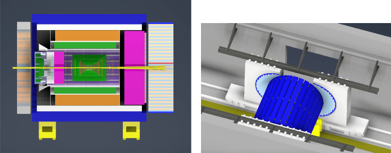
To accommodate the magnet coil, the cryostat has an outer diameter of 4.11 m and a total length of 3.84 m. For initial design studies, a simplified barrel was used to reduce the modeling time. For magnetic analysis, only the hadron calorimeters have been considered as these are the only subdetectors constructed from magnetic material. The HCals have three main components: an electron-endcap HCal, a hadron-endcap HCal and a barrel HCal, as illustrated in Fig. 2. The magnet center is shifted by 25 cm with respect to the center of the detector and the nominal interaction point towards the electron endcap. This compensates for the different iron content and location of the two endcap calorimeters, thereby reducing the axial forces on the magnet to enable a solenoid design with minimum mechanical support. The current model assumes a generic B-H curve; actual material properties will be incorporated into the model at a later date.
2.2.1 Field shape
Key design constrains for the magnet were the flat-field region, the shape of the magnetic field lines in the volume of the dRICH in the forward direction, and limits on the tolerable stray field for the accelerator components. The space for the dRICH extends from cm to cm with an angular range of 3.5∘ to 25∘. Ideally, the field lines in this region should be projective to minimize distortions due to track bending in the gaseous volume of the dRICH (see Sec. 2.5.1). This requirement affects the uniformity achievable in the flat-field region and therefore requires careful optimization. To make the effect of the solenoid on the accelerator tolerable, the requirement is for a stray field smaller than 5G in the region m and m, respectively. The Rapid Cycling Synchrotron (RCS) is radially 335.2 cm from the magnet central axis where the integral field requirement over the length of the detector is Tm. The currently achieved fringe fields will be further improved in the next design phase.
The electromagnetic analysis was performed using the SIMULIA Opera simulation package. The field in the coil and in the HCals is shown in Fig. 3 and the main design parameters are summarized in Tab. 3.
| Parameter | Value | Units |
|---|---|---|
| B in the solenoid centre | 3.02 | T |
| Peak field in the coil | 4.19 | T |
| Stored energy | 175.5 | MJ |
| B @ z = -5.6 m | 10.5 | mT |
| B @ z = 7.2 m | 5.2 | mT |
| Homogeneity in flat field area | 27.5 | % |
| Projectivity in the forward RICH area | 10.4 | T/Amm2 |
| Axial force | 37 | kN |
2.2.2 Choice of conductor
In order to minimize the material budget in front of the barrel HCal, a NiTi Rutherford cable with a 5N AlNi1% stabilizer is chosen. The Rutherford cable is made up of 40, 0.84 mm diameter Cu-(NbTi) strands. Preliminary calculations show that this conductor is a safe choice with a 1.96 K temperature margin (see Sec. 2.2.4), a 35% current margin, and approximately a 50 K hot spot temperature in the event of a quench.
2.2.3 Mechanical design
The preliminary mechanical analysis has been carried out in 2-D. This analysis assumes the orthotropic behavior of the conductor and assumes a sliding contact between the magnet and the support structure. The support structure is 50 mm thick aluminum. Calculations of both the cool down and energization loads have been performed. In both cases, the stresses in the coil and the support structure are well below the design limits. The peak stress at energization (worst case scenario) is 63 MPa in the coils and 73 MPa in the support structure, while the design limits are 70 MPa and 135 MPa, respectively. The limits are based on two-thirds of the yield stress of the material.
2.2.4 Cryogenic design
The available cryogens for the magnet are supercritical helium at 4.5 K and 3.5 bar for the cold mass and helium gas at 45 K and 15 bar for the shields. The return gas of the cold mass and the shields are expected to be at 4.8 K at 1.28 bar and 80 K at 14 bar, respectively. The allotted power budget for the magnet is 100 W at 4.5 K and around 400 W at 80 K. Based on the magnet size and type, the magnet cooling will be done using the thermosiphon method. Preliminary heat load calculations show that the load is well within the available limits.
2.3 Vertex and Tracking System
ATHENA will utilize silicon MAPS near the interaction point and Micro-Pattern Gaseous Detectors (MPGDs) farther out. This configuration allows for a low material budget tracking system with sufficient redundancy over a large lever arm, which is critical to achieve the required momentum resolution. The layout of the vertex and tracking system is illustrated in Fig. 4. A compact inner silicon barrel consists of three vertex layers and two barrel layers occupying a region that has a maximum radius of and a total length of . The vertex layers are made of large-area, wafer-scale, stitched sensors that are bent around the beam pipe, allowing the first vertex layer to be placed very close to the interaction point at a radius of . The barrel layers comprise a more traditional stave design that uses smaller stitched sensors. The two outermost barrel layers will each comprise two closely-spaced 2-D layers of Micromegas with mean radii of approximately and , and maximum total length of approximately .
In the forward and backward directions, the vertex and tracking system consists of silicon disks augmented by large-area GEMs. The silicon disks will use the same sensor technology as the vertex and barrel layers. In an effort to minimize material in the backward (electron-going) direction, there are five disks, while in the forward (proton/nucleus-going) direction there are six disks. They start either side of the interaction point and extend to in the backward direction and in the forward direction. The maximum outer radius of the disks is approximately . The minimum radii are determined by the divergence of the beam pipe. Two triple-GEMs detectors with an inner and outer radius of about and , respectively, are implemented near the two silicon disks furthest from the IP to extend the acceptance for tracks and provide additional hit points for track reconstruction in the pseudorapidity interval . Finally, a RWell detector, with a radius of about is located behind the dRICH detector in the forward direction. This detector helps seed the dRICH ring finder and improves the momentum resolution in the forward direction.
2.3.1 Choice of technology
The silicon detectors will use the latest MAPS technology that was identified in the Yellow Report [AbdulKhalek:2021gbh] as the best candidate to meet the stringent requirements on vertex and momentum resolution. This technology is currently being developed for an upgrade of the inner tracking system of the ALICE experiment at the LHC at CERN. The upgraded ALICE detector (ITS3) is expected to be ready for installation during the next long LHC shutdown from 2026 to 2028.
The specifications of the proposed ITS3 sensor already meet most, if not all, of the requirements of the EIC. ATHENA plans to use the ITS3 sensor in all parts of its silicon tracker with size optimized for vertex layers with minimal material and for cost effective large area coverage in barrel layers and disks. The overarching goal of ITS3 is to achieve a pixel pitch down to while keeping power dissipation below to construct a vertex detector with a space point resolution of better than for a material thickness of just per layer. By comparison, the vertex layers in the current ALICE ITS (ITS2) have a pixel pitch of approximately , dissipate and each have a material thickness of .
For the three innermost vertex layers of the tracking system, ATHENA will adopt the ALICE ITS3 concept of large-area, wafer-scale stitched sensors, thinned to below , bent around the beam pipe and held in place using low mass carbon fiber support structures [ITS3det]. The low power dissipation of the sensor will enable air cooling of the vertex layers, which is a key factor in reducing the material thickness of the innermost tracking layers, crucial to achieve the required vertex reconstruction resolution. The barrel layers and forward/backward disks will use more conventional flat sensors, also stitched but not to wafer scale, mounted on flat support structures: staves and half-disks. This leads to an estimate of in each of the two barrel layers and for the disks, based on the ALICE ITS2 [ITS2] experience and the anticipated power dissipation of the new sensor.
The EIC Silicon Consortium has grown out of the EIC generic detector R&D program (eRD16/eRD18/eRD25) and its leadership is made up of members of the ATHENA collaboration. The EIC Silicon Consortium will co-develop with ALICE-ITS3 the wafer-scale sensor for the vertex layers, while also developing an EIC-specific, stitched but not wafer-scale version of the same sensor for the barrel layers and disks, together with support structures and services (see Sec. 2.11).
MPGD technologies such as GEMs, Micromegas and RWell detectors are a cost-effective solution for large-area tracking systems requiring a low material budget. GEMs and Micromegas are both mature technologies and have been used in many nuclear and high-energy physics experiments including COMPASS and the upgrades of ATLAS, CMS, ALICE, and LHCb at CERN; SBS, CLAS12, and PRad at Jefferson Lab; as well as the STAR Forward GEM Tracker and PHENIX Hadron Blind Detector at BNL. In general, MPGDs are gaseous devices for electron amplification with a high granularity strip or pad anode readout to provide good 2-D space point resolution (), fast signals (), high rate capability (up to 1 ), low material budget, radiation hardness and large area coverage. Through the EIC generic detector R&D program (eRD3/eRD6 [Posik:2018oat, Posik:2015gha, Gnanvo:2014hpa, Gnanvo:2015xda, Hohlmann:2017sqj, Zhang:2017dqw, Zhang:2016vbk, Zhang:2015kxy, Zhang:2015pqa, Vandenbroucke2018, azmoun:2020tns, azmoun:2021tns]) advancements towards low material and large-area MPGD detectors with low channel counts and high granularity readout structures have been made. Each Micromegas layer in the barrel and each of the forward/backward triple-GEM disks has a material thickness well below . The addition of a Time-of-Flight (ToF)-layer based on AC-LGAD in the barrel will improve the pattern recognition and tracking performance at higher . In the evaluation of the tracker performance discussed in the following this device was not taken into account.
2.3.2 Requirements and subsystem performance
The combined silicon and gaseous detector technology design, illustrated in Fig. 4, has been chosen after careful consideration of tracking and vertex reconstruction performance, cost, ease of integration, and with the overarching aim of minimizing material. The solution allows the services to the central silicon barrel to be routed along the conical/cylindrical support structure that encapsulates the silicon disks.
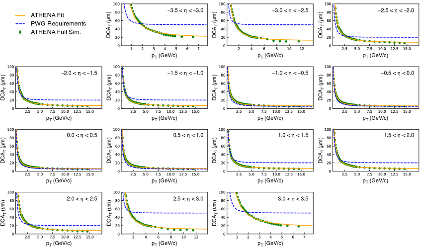
The overall performance of the chosen vertex and tracking system is illustrated in Fig. 5 and Fig. 6, which shows the reconstructed relative momentum resolution () as a function of momentum (Fig. 5) and the transverse distance of closest approach () to the primary vertex (pointing resolution) as a function of transverse momentum (Fig. 6) for primary pions generated in three bins of pseudorapidity. The dashed lines represent the corresponding performance requirements from the EIC Yellow Report. The relative momentum and transverse pointing resolutions were obtained from full GEANT4 simulations and have been parameterized by fitting the same functional forms as the Yellow Report requirements. The fits were performed in bins and then combined to match the binning found in the Yellow Report. The results are summarized in Table 4 presenting a side-by-side comparison of the achieved performance and detector requirements as a function of pseudorapidity.
| Momentum resolution | Transverse pointing resolution | |||
|---|---|---|---|---|
| Performance | Requirements | Performance | Requirements | |
| -3.5 -2.5 | ||||
| -2.5 -1.0 | ||||
| -1.0 1.0 | ||||
| 1.0 2.5 | ||||
| 2.5 3.5 | ||||
The tracking performance meets or exceeds the momentum resolution requirements stated in the Yellow Report, except for the most backward pseudorapidities. One way to improve this would be to further increase the of the tracking system. However, a significantly larger field value is impractical, the tracking lever arm cannot be extended further due to spatial constraints in the current ATHENA detector configuration, and adding silicon disks to the proposed array would worsen the momentum performance because of the additional material they would introduce. The backward momentum resolution requirement in the Yellow Report can thus not be met by current detector technology. Achieving the science will require the combination of tracking information with that from the high resolution crystal electron-endcap Electromagnetic Calorimeter (nECal) to improve the electron measurement, further minimization of the material inside the backward disk array, a different trade-off with the PID subsystem in the associated acceptance region, an alternative analysis approach, or a combination of these factors.
2.4 Calorimetry
2.4.1 Electron endcap electromagnetic calorimeter
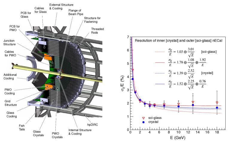
The electron-endcap Electromagnetic Calorimeter (nECal)is a high-resolution electromagnetic calorimeter designed for precision measurements of the energy of scattered electrons and final-state photons in the region . Based on the Yellow Report [AbdulKhalek:2021gbh], the required high energy resolution is driven by inclusive DIS where precise measurement of scattered electrons is critical to determine the event kinematics. The inner part of the nECal consists of 1976 PbWO4 crystals, each of size [Horn:2019beh, Asaturyan:2021ese]. The expected energy resolution for PbWO4 crystals is [AbdulKhalek:2021gbh]. The outer part of the nECal consists of 1104 SciGlass blocks, each of size [Buchner:1988fu, E705:1993imr], with expected energy resolution of . Both the PbWO4 and SciGlass blocks will be read out with arrays of Silicon Photomultipliers (SiPMs).
The technology choice and overall design concept of the nECal is the same as in the Yellow Report. Since the Yellow Report, the design has been further developed by the EEEMCAL consortium [Horn:2020eoi].
The nECal calorimeter concept was developed as part of the EIC generic detector R&D program [eRD1:2017aaa]. The team collaborated closely with producers of PbWO4 crystals and SciGlass to establish robust QA protocols at all stages of production, ensuring the highest quality of blocks. R&D for SciGlass will continue under the auspices of the EIC Project to show the feasibility of production scale up. In the event that SciGlass R&D is delayed, the fallback technology is lead glass.
A detailed design of the nECal is underway among the collaborating institutions of EEEMCAL, focussing on mechanical design, scintillator, readout, and software/simulation development. Pre-design activities, in particular for the support structure have started in 2021. The mechanical integration of this detector is shown in Fig. 7. This concept is based upon existing detectors the team has constructed, and in particular, the Neutral Particle Spectrometer at Jefferson Lab [Horn:2015yma]. The final assembly of the detector will be performed at BNL.
2.4.2 Barrel electromagnetic calorimeter
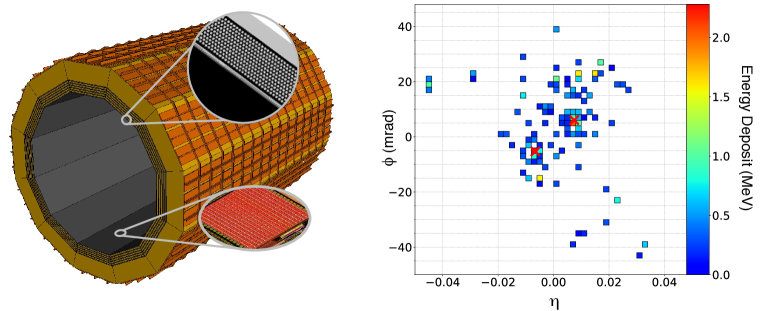
The barrel Electromagnetic Calorimeter (bECal)will detect scattered and secondary electrons and separate them from pions, detect and reconstruct full kinematic information for photons, and provide sufficient spatial resolution to identify neutral pions from decay at high momenta. The proposed design is hybrid, using light-collecting calorimetry based on SciFi embedded in Pb and imaging calorimetry based on AstroPix monolithic silicon sensors [brewer2021astropix]. The imaging of particle showers is achieved by six layers of silicon sensors interleaved with five Pb/SciFi layers, followed by a thick layer of Pb/SciFi calorimeter resulting in a total radiation thickness of about 20 X0. The barrel is composed of 12 staves, as shown in Fig. 8 presenting the geometry of the barrel calorimeter used in the current ATHENA simulations. The inner radius of the barrel is 103 cm. The first (closest to the beam) six layers are imaging layers with a width of 55.2 cm and length of 405 cm. Each imaging layer is separated by a Pb/SciFi layer that is about 1.59 cm thick. Because of ATHENA’s geometry, the bECal not only functions as the barrel calorimeter, but also provides significant coverage in the electron-going direction for the overall ECal system.
The Yellow Report stipulates that the bECal should have energy resolution of approximately (10–12)%/ (1–3)%, electron-pion separation up to , spatial resolution to separate from decay for momenta up to 15 GeV/c, and the capability to detect photons down to 100 MeV.
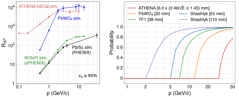
This hybrid design provides precise measurements of both the energy and position of the incident particle’s cascade in 3-D. Utilizing Artificial Intelligence (AI) techniques for pattern recognition of the 3-D shower images, this calorimeter will provide pion-electron rejection better than that achievable with traditional sampling calorimetry, especially at lower particle energies ; see Fig. 9. The layers of the Pb/SciFi sampling calorimeter improve the overall sampling fraction and hence, the energy resolution of the calorimeter. Table 5 summarizes the expected detector performance based on simulations with AstroPix sensor digitization and reconstruction algorithms for both 3-D and 2-D shower clustering.
The imaging layers are based on off-the-shelf AstroPix sensors, the successor of ATLASPix [schoening2020mupix], a low-power pixel sensor developed for ATLAS, and further optimized for the NASA AMEGO-X [fleischhack2021amegox] mission. These sensors have excellent energy resolution at low energy ( 7% at 30 keV) and do not have stringent power and cooling requirements. This technology was discussed in the Yellow Report as an alternative to light-collecting calorimeters. The imaging capabilities replace the need for the projective geometry of the Yellow Report W/SciFi calorimeter. The proposed Pb/SciFi design is based on the existing GlueX barrel calorimeter with an energy resolution of [Beattie:2018xsk] and -position resolution at normal incident angle [leverington:2008zz], exceeding the Yellow Report requirements. These numbers were obtained from fits to low-energy data ( GeV) that do not fully constrain the constant term.
The fine pixelation of the bECal allows for tagging of final state radiative photons that may be extremely close to the scattered electron. This is important for radiative corrections, enabling the benchmarking of e+A Monte Carlo generators. Furthermore, the first Si layer provides a space point for the hpDIRC reconstruction, obviating the need for additional large-radius tracking. The outer, thick layer of Pb/SciFi contributes to neutral hadron identification since 70% or more of produced neutrons will begin showering within the bECal. This partially compensates for losses in the magnet material and improves the overall hadronic reconstruction. The tracking layers lower the threshold of separation, expanding the available phase space for all physics objectives. Furthermore, the 3-D shower profiles measured by the bECal enable effective identification.
The overall concept for a tracking calorimeter is novel, but it relies on two well-developed technologies. The tracking layers rely on the technology of CMOS pixel sensors; a first version of the AstroPix sensor has already been delivered, and the second version is expected soon. Pb/SciFi technology is very mature, having been used for over 30 years; this design will scale up the design for the KLOE and GlueX experiments [Adinolfi:2002zx, Beattie:2018xsk].
| Energy Resolution | |
|---|---|
| separation | 99.8% pion rejection with 95% electron efficiency at GeV/cb. |
| MeVc | |
| Spatial Resolution | Cluster position resolution for 5 GeV photons at normal incident angle is below mm (at the surface of the stave cm) or . For comparison, the minimal opening angle of photons from at 15 GeV is (about 19 mm – 37 pixels – of separation at cm). |
aBased on the photon simulations with and . The constant term does not include calibration effects.
bBased on simulation for a standalone bECal, see Fig. 9 for detailed results.
cBased on simulations, 100 MeV photons leave an energy deposit of MeV in SciFi layers and of MeV in the imaging layers. This simulation includes digitization with electronics noise and a noise suppression cut.
2.4.3 Hadron endcap electromagnetic and hadronic calorimeters
ATHENA’s high resolution, high granularity, compact hadron endcap calorimeter system consists of a compensated hadron-endcap Electromagnetic Calorimeter (pECal)and Fe/Scint (20 mm / 3 mm) sandwich hadron-endcap Hadron Calorimeter (pHCal). The expected electromagnetic resolution is , while the hadronic resolution is , including a tail-catcher cut. This is based on GEANT4 simulations and requires experimental validation. The experimentally achieved energy resolution with a similar but thinner (only 4.5 ) HCal and shashlyk ECal system built for STAR was . The e/h ratio for the pECal is tuned to be above 10 GeV, while for the pHCal it is . The pHCal will have four longitudinal sections for software compensation, i.e., re-weighting energy deposition in sections with localized high electromagnetic fraction [FeHCal], and 3-D shower imaging. The transverse tower size is 2.5 2.5 cm2 for the pECal and 10 10 cm2 for the pHCal, respectively. The longitudinal space required for about seven interaction lengths is 150 cm. The pHCal absorber structure serves as a support for the pECal. Both calorimeters will be read out with SiPMs. The choice of technology is the same as for the reference detector described in the EIC CDR [EIC-CDR].
The pECal is made of W powder with embedded scintillating fibers [Tsai:2012cpa]. This technology was pioneered as part of the generic detector R&D program for EIC, adopted by sPHENIX. A novel, efficient, and scalable construction method [Tsai:2015bna] developed for the STAR Forward Calorimeter System (FCS), will be used to build the pHCal.
Longitudinal segmentation in the pHCal will be achieved by using scintillation tiles with two different time constants, similar to the CALEIDO2 Prototype for the ILC [CALEIDO:2001vdz]. Thus, with just two independent readout channels per tower, longitudinal information from four segments of the tower becomes available. The longitudinal segmentation of the pHCal and the achievable hadronic energy resolution will be verified in the near future with beam tests of a large scale prototype. A fallback solution, in case the two-channel readout technique would not be optimal, is to use an optical readout scheme with additional independent readout of the three last scintillation tiles in the pHCal towers. This scheme is similar to that used in the STAR FCS, and was studied in EIC generic detector R&D.
The hadron endcap will be assembled in situ, as was done for the STAR FCS. The STAR forward HCal will be re-used for the ATHENA pHCal. a region of the pHCal close to the beam pipe will have a potential upgrade path to replace scintillation tiles with Si sensors.
2.4.4 Hadronic calorimeters in electron endcap and barrel
In combination with information from the electromagnetic calorimeters, tracking and PID detectors, the hadron calorimeters in electron endcap and barrel assist with the detection of neutral hadrons [Page_2020]. The barrel Hadron Calorimeter (bHCal) with passive magnet steel provides mechanical support for all the detector systems of ATHENA. The steel structures of all the hadron calorimeters provide the return flux path for the magnetic field.
The thickness of the ATHENA Magnet ( 1.3 ) between the bECal and bHCal precludes good calorimetric energy measurements of hadrons. The bECal in front of the magnet cryostat will be deep, thus it is sufficient to instrument only about two (tail-catcher) after the magnet cryostat to contain about 95% of hadronic showers. The remaining steel required for the flux return and mechanical support of the barrel detectors will consist of re-used flux return steel bars of the STAR Magnet. A barrel made of these bars will weigh about 540 tons.
The bHCal is a five layer steel and scintillator sandwich (4 cm/5 mm layer structure). ATHENA will re-use existing scintillation mega-tiles from the STAR barrel ECal [STAR:2002ymp]. These tiles have lost less than 5% of their initial light yield after 20 years of operation. Existing scintillation mega-tiles consist of 80 optically isolated scintillation tiles with sigma grooves and wavelength-shifting fibers for light collection. The tiles are arranged in a projective geometry with excellent granularity 0.05 x 0.05 in and azimuthal angle . Each individual tile will be read out with SiPMs. The expected light yield will exceed 10 photoelectrons for Minimum Ionizing Particles (MIPs) providing very good efficiency for low energy hits. Pre-assembled and calibrated with cosmic muons, mega-tile cassettes will be inserted into the bHCal. Moderate energy resolution for hadrons in the barrel region can be obtained from the bECal Pb/SciFi layers.
A similar approach will be used for the nHCal by utilizing scintillation mega-tiles from the STAR endcap ECal [STAR:2002eml]. The structure for the nHCal is similar to the bHCal, consisting of approximately 10 layers. The exact number of instrumented layers in both detectors is under optimization.
Re-using components from the STAR detector (magnet steel, cradles, scintillation mega-tiles) significantly reduces the cost of these two subsystems.
2.5 Particle Identification
Particle identification in ATHENA requires multiple technologies to address the physics goals. Measurements of Cherenkov radiation provide the greatest reach at higher momentum, but are limited in their low-momentum reach. Furthermore, the -dependence of the momentum spectrum along with space constraints require distinct technologies in the forward, backward, and barrel regions. Our solution to this challenge involves:
-
•
A dual radiator RICH (dRICH) in the forward region utilizing aerogel and gas radiators focused by mirrors onto a focal plane instrumented by SiPMs with built-in capability to "anneal-in-place" to combat the inevitable dark current generated by radiation damage.
-
•
A 100-cm radius high-performance DIRC (hpDIRC) very close to the design of the Yellow Report in the central region. The hpDIRC is complemented by an AC-LGAD ToF detector at a 52.5 cm radius. The AC-LGAD layer dramatically improves the PID reach to low momentum by catching particles that do not reach the hpDIRC, while sidestepping the limitations of Cherenkov detectors at lower momenta.
-
•
A proximity-focusing aerogel RICH (pfRICH) with 40 cm proximity gap. This deviates from the mRICH technology used in the Yellow Report. This design features minimal material budget, easy pattern recognition, large acceptance, and can simultaneously function as a threshold gas Cherenkov detector.
2.5.1 Forward direction
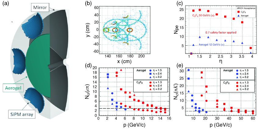
dRICH: The highest momentum particles produced at the EIC are emitted in the forward direction. Gas-based Cherenkov ring imaging is the only presently-known technology that addresses -K-p separation up to the required 50 GeV/c. Optimization of any Cherenkov detector design effectively boils down to minimizing the Cherenkov angular resolution of a single photon’s contribution to the ring (linear dependence) and maximizing the number of detected photons per ring ( dependence). The single photon resolution is affected by internal factors (radiator chromaticity, optical aberration, pixel size) as well as external factors including stray magnetic field and track pointing resolution. The ATHENA design is the result of an intensive optimization on all fronts using full GEANT simulations at the level of optical photon propagation.
ATHENA underwent extensive studies of the magnet design with simulations demonstrating that the most significant positive impact involved distancing the dRICH from the collision point. The optics of the dRICH also represent a solved challenge with broad implications. The focal plane location entails an optimization involving three factors: maximizing the radiator length (prefers longer focal length), shielding the photon sensors from radiation (prefers tilted mirrors), and fitting the detector into the available space. This is realized by careful positioning of the dRICH detector with respect to the ATHENA magnet. The optimization is a practical implementation of the dRICH concept from the Yellow Report that fully realizes the device’s potential in the face of the compromises that must be made in a realistic detector design.
The sensor choice for a dRICH is quite challenging. After careful consideration, the only viable choice is the well known SiPM technology. These devices are ideal in terms of quantum efficiency, sensitive wavelength range, and single-photon signal size. The difficult aspect regards dark currents that grow with radiation exposure. It has been demonstrated by studies at INFN [Calvi:2018ulw] that this damage can be repaired by thermal annealing, while R&D efforts towards in-situ annealing are ongoing. The ATHENA design thereby features SiPM-based photon sensors in both the dRICH and the backward pfRICH. Detailed calculations of the worst-case dark current rates have been used as the basis of estimates for the DAQ needs of the dRICH. Figure 10 shows the layout and performance of the ATHENA dRICH. As described previously, the optimization of the dRICH location (panel a) and optics (panel b) have already achieved the performance requirements in the Yellow Report.
2.5.2 Barrel region
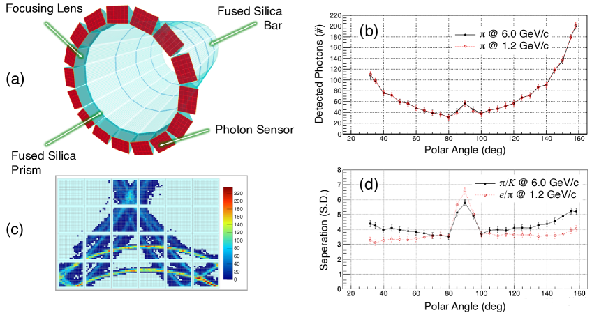
hpDIRC: The hpDIRC closely resembles the concept described in the Yellow Report. This presents an evolution of the original BaBar design. The ATHENA barrel is surrounded by a series of radiator bars made of synthetic fused silica. Rings are imaged in an ”expansion volume”, onto a focal plane containing photon detectors oriented normal to the magnetic field. The detector and its performance are shown in Fig. 11. The hpDIRC focuses the ring onto a sensor plane. This will improves the performance of the device compared to the BaBar DIRC (doubling the 3- separation limits), while making the readout system significantly more compact.
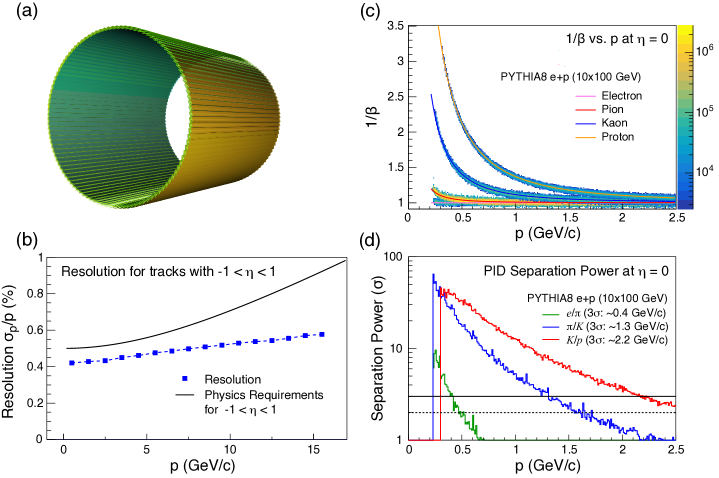
AC-LGAD ToF: ATHENA defines positive PID as a signal beyond the Cherenkov threshold for -radiation. As such, the positive PID range for the DIRC begins at a momentum higher than 0.47 GeV/c (the threshold in synthetic fused silica). This nicely matches the momentum cutoff of the ATHENA magnetic field. Extending the range downward requires a dedicated detector located at a smaller radius. AC-LGAD devices deliver an excellent time resolution ( ps/layer) and spatial resolution. A single-layer array of AC-LGAD devices at a radius of 52.5 cm in the ATHENA design provides an effective PID coverage between 0.23 and 1.3 GeV/c for a 3 T field, and an additional spatial hit to supplement the tracking system in the barrel region. Figure 12 shows the configuration of the barrel Time-of-Flight (bToF).
One should note that state-of-the-art timing detectors present many technology challenges beyond just the performance of the sensor. These include, but are not limited to, the determination of a start time or , and timing jitter which is invariably present in a large electronic system sending signals (such as the crossing clock) over long distances. Because we emphasize the identification of particles at momenta below 1 GeV/c, conservative estimates of the uncertainty in using only the crossing clock and time distribution jitter show that this system will easily perform beyond its requirements for -K-p separation.
2.5.3 Backward direction
pfRICH: In the backward direction, PID is provided by an aerogel radiator proximity-focusing RICH with a 40 cm proximity gap, shown in Fig. 13. This technology choice maximizes acceptance while minimizing material in front of the nECal, with a uniform performance across its entire aperture. The simplicity of the design makes the pattern recognition much simpler than for typical RICH detectors. The baseline aerogel and photon detector technologies for the pfRICH are identical to those for the dRICH. This minimizes the number of PID technologies used in ATHENA.
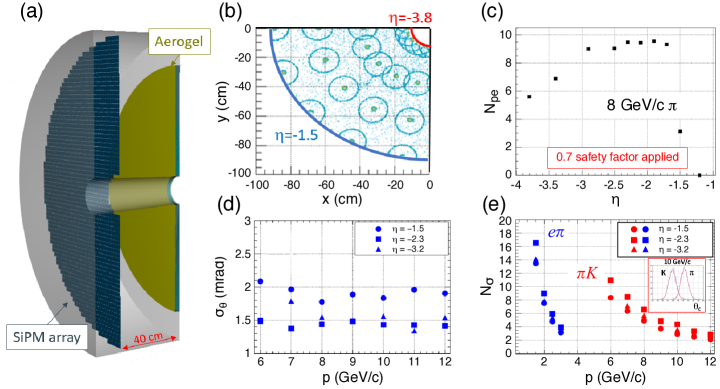
One additional feature emerges from this design: The Yellow Report identifies the need for additional electron identification (beyond from calorimetry and tracking) in the backward direction at momenta up to 4 GeV/c. While this is not possible with an aerogel-based design, this can be achieved with a traditional gas threshold Cherenkov detector. The 40 cm gap between the aerogel and the sensor plane is sufficiently long for threshold-based electron identification, further improving ATHENA’s PID performance in the backward direction.
2.6 Far Forward Detectors
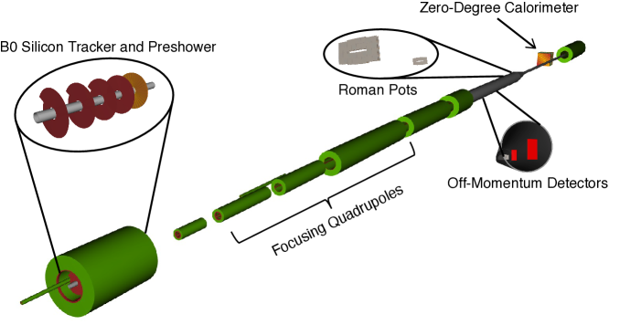
EIC collisions include many final-states with charged or neutral particles with . These particles are outside the acceptance of the central detector and therefore require detectors integrated with the accelerator beamline. Maximum acceptance across all beam energies and species requires multiple subsystems, whose acceptance is dictated by the Interaction Region (IR) design. This is summarized in Tab. 6. A 3-D layout of the far-forward region is shown in Fig. 14.
| Detector | accep. [mrad] | Rigidity accep. | Particles | Technology | ||||
|---|---|---|---|---|---|---|---|---|
| B0 tracker | 5.5–20.0 | N/A |
|
|
||||
| Off-Momentum Detector | 0.0–5.0 | 45%–65% | Charged particles | AC-LGAD | ||||
| Roman Pots | 0.0–5.0 | 60%–95%∗ |
|
AC-LGAD | ||||
| Zero-Degree Calorimeter | 0.0–4.0 | N/A |
|
|
2.6.1 Technology choices
The B0 spectrometer requires approximately 20 m position resolution to provide the required resolution for high-momentum hadrons near the beam line and good timing resolution to aid in background rejection, and to correct for effective vertex smearing from the crab cavity rotation. Our design consists of three silicon MAPS disks serving as the first, second, and fourth layers of the detector, complemented by a single AC-LGAD layer with 500 m pixel pitch and ps timing resolution. Each tracking layer is separated by 30 cm. The silicon preshower following the tracker has two radiation lengths of lead as a photon converter, and a layer of silicon to tag the produced lepton pair. We envision use of AC-LGAD sensors for the preshower. These sensors enable the required spatial resolution to measure lepton pairs while providing excellent timing resolution to reduce background contamination. While some observables could benefit from an expanded electromagnetic calorimeter, this is precluded by engineering constraints (size, weight).
The Off-Momentum Detectors (OMDs) and Roman Pots (RPs) each consist of two stations separated by 2 m, with each station consisting of two active layers. Both detectors require spatial resolution better than 150m, and 30 ps timing resolution , making AC-LGADs an ideal choice for both detectors.
We will insert the silicon detector packages for the RP and OMD directly into the beam pipe vacuum (i.e., without the usual “pot" vessels) with thin foils surrounding the detector packages to maximize acceptance. The RP detectors, in particular, need to be inserted (vertically only due to spatial constraints) into the beam line as close to the beam as possible (usually a few mm from the beam, depending on the beam optics).
The Zero-Degree Calorimeter (ZDC) consists of the following major systems: a) silicon charged particle veto layer, b) W/SciFi sampling calorimeter with 2.5 2.5 cm2 towers, 17 cm long (identical to the pECal), and c) Pb/Scint imaging hadronic calorimeter composed of a total of 120 layers of 1 cm Pb and 0.25 cm scintillator, corresponding to seven . The full ZDC delivers approximately eight in total.
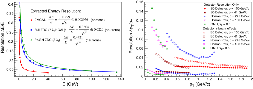
2.6.2 Detector performance
Resolutions for the far forward detectors are shown in Fig. 15. The RPs and OMDs utilize a transfer matrix which specifies the transport of protons from the IP through the magnetic elements of the far-forward lattice. However, the OMDs require a more sophisticated approach to handle the non-linear transport of protons with low rigidity (% or less); these trajectories are at the edges of the quadrupole fields, which cause additional bending not captured by the linear transport matrices.
The performance demonstrated by the full GEANT4 simulations of the baseline ZDC is shown in the left panel of Fig. 15. Preliminary results obtained from the W/SciFi + Pb/Scint ZDC simulations when compared to test beam data indicate that the performance meets the physics requirements. In addition, an 8 version of the detector was benchmarked against ZEUS test beam data. For photons, the measured performance of the W/SciFi ECal is consistent with previous studies. Simulations were made for photon energies down to 100 MeV for photons, the results indicating that this W/SciFi ECal can measure low energy photons.
2.7 Luminosity Measurements and Low- Tagging
As described in the Yellow Report, we will measure the EIC luminosity using the bremsstrahlung process [AbdulKhalek:2021gbh]. To meet the requirements of 1% precision in the absolute luminosity measurement and 0.01% precision in relative luminosity, we add further instrumentation compared to the Yellow Report. This will enable data-driven corrections and systematic checks, and facilitate three largely independent and complementary measurement methods [Piotrzkowski:2021cwj]. The first method is based on counting photons converted in a thin exit window by applying a horizontal magnetic field and measuring pairs with two small calorimeters, CALup/down (left panel of Fig. 16). This method is not sensitive to direct Synchrotron Radiation (SR), but at the nominal e+p luminosity the effects of event pileup are mitigated by two small hodoscopes, HSup/down. In the second method, the total energy carried by unconverted photons will be measured by the (movable) calorimeter, PCALf. By construction, it is not affected by the event pileup but direct SR must be suppressed using a set of filters, F1 and F2. This simple and robust measurement will also enable the online luminosity monitoring. The third method is based on counting the unconverted photons using the movable calorimeter, PCALc, which will be used at small electron bunch current, when the event pileup and SR levels are low. This is also essential to validate special corrections to the bremsstrahlung cross section [Piotrzkowski:2020uya]. All three measurements will be performed on a bunch-by-bunch basis, with negligible deadtime.
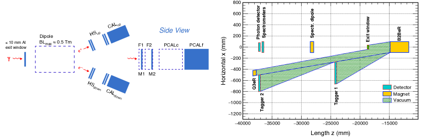
The detectors CALup/down and PCALc will be made using the same technology: Spaghetti W-calorimeter with radiation-hard scintillating fiber, read out with fast PMTs . Due to the very large irradiation levels in this location, PCALf and the SR monitors M1 and M2, will use Cherenkov-radiating quartz fibers read out by SiPMs. Each of the hodoscopes HSup/down will comprise four front (back) planes made by straight 1(2) mm square scintillating fibers, also read out by SiPMs. Half of the fibers will be horizontal and half will be rotated by a small angle to allow for the determination of the horizontal coordinates of the hits. Signals from all detectors will be sampled with 100 MHz custom readout chips.
Bremsstrahlung electrons will be measured by two small detectors, Tagger 1 and Tagger 2, placed behind thin exit windows about 24 m and 37 m from IP6, respectively (right panel of Fig. 16). They will be very similar in design to CALup/down and will have similar hodoscopes in front. The major difference is that half of their fibers are horizontal and half are vertical.
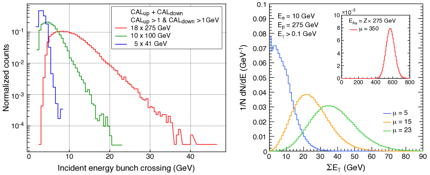
While all detectors will be built using existing technologies, the huge bremsstrahlung event rates at the EIC, sometimes in excess of 10 GHz (Fig. 17), make the design of the readout electronics and of radiation hard detectors challenging. Consequently, optimization of both the detector and electronics designs will require extensive studies and verification using test beams. This will include the development of suitable techniques to control, in-situ, all relevant systematic effects, as well as providing the Data Acquisition (DAQ) system for the luminosity measurement.
Our design will permit efficient tagging of very low- events during the first two years of EIC running, when the event pileup is expected to be relatively low. An upgrade path after the initial phase consists of replacing the tagger hodoscopes with thin, high-resolution pixel detectors operated in the primary beam vacuum and read out by Timepix4 sensors [Ballabriga:2020nbo]. This will enable a very effective separation between the bremsstrahlung and low- electrons at nominal EIC luminosities [Adam:2021hei].
2.8 DAQ and Readout Electronics
The EIC will provide e+p and e+A collisions at rates up to 0.5 MHz with beam bunches separated by 10 ns. ATHENA will digitize hit position, charge and timing signals originating from nearly 30 distinct subdetectors using a variety of technologies including SiPMs, MAPS, AC-LGADs, Micro-Channel Plate PMTs (MCP-PMTs), Photomultiplier Tubes (PMTs), and MPGDs. The signals will be zero-suppressed where possible, digitized and aggregated using front-end boards containing a variety of Application-Specific Integrated Circuits (ASICs) and Field-Programmable Gate Arrays (FPGAs). The primary function of the DAQ system will be to aggregate data and record all collision related hits. The system must also control, configure, and monitor the acquisition of data and ensure data quality.
The chosen architecture is illustrated in Fig. 18. It will be a streaming DAQ system following the scheme outlined in the Yellow Report. A global timing system is needed to synchronize the system with the bunch structure of the EIC to a resolution of 10 ps. Front End Link eXchange (FELIX) boards, implementing GBTx links towards Front-End Electronics (FEE) with 10 Gbps/link bandwidth, are used as a basis to provide common interface between the Front-End Boards (FEBs) and the commodity DAQ computers. The FELIX boards are capable of transferring data to the DAQ computers and of transmitting clock and configuration information to the FEBs. A farm of 50 computers on a 100 Gbps Ethernet network is needed to read out the FELIX boards. An additional 50 computers will be required to perform further data reduction, ensure data integrity and monitoring, buffer, and transfer data to tape.
An estimated maximum data volume by detector subsystem is shown in Tab. 7. The 2.5 Tbps stream of data transmitted from the FEBs needs to be reduced to 100 Gbps for long-term storage without losing detector hits that arise from beam collisions.
| Detector | Channels | DAQ Input (Gbps) | DAQ Output (Gbps) |
|---|---|---|---|
| B0 Si | 400M | <1 | <1 |
| B0 AC-LGAD | 500k | <1 | <1 |
| RP+OMD+ZDC | 700k | <1 | <1 |
| FB Cal | 4k | 80 | 1 |
| ECal | 34k | 5 | 5 |
| HCal | 39k | 5.5 | 5.5 |
| Imaging bECal | 619M | 4 | 4 |
| Si Tracking | 60B | 5 | 5 |
| Micromegas Tracking | 66k | 2.6 | .6 |
| GEM Tracking | 28k | 2.4 | .5 |
| µRWELL Tracking | 50k | 2.4 | .5 |
| dRICH | 300k | 1830 | 14 |
| pfRICH | 225k | 1380 | 12 |
| DIRC | 100k | 11 | 11 |
| TOF | 332k | 3 | .8 |
| Total | 3334 | 62.9 |
The biggest challenge to the goal of fully reading out the ATHENA detector with no deadtime will be the dark currents from the SiPM readout, expected to gradually increase with accumulated radiation dose. The current estimates assume an average rate of up to 300 kHz/sensor over the full detector. This dark current is indistinguishable from signals from single photoelectrons. We hope to reduce this by a factor of three to five in the FEBs using sample cuts relative to the bunch crossing time. Further reduction can be obtained by a software trigger applied in the DAQ computers. Requiring a collision to be present will provide a data reduction by a factor of at least 200 allowing the ATHENA DAQ to write all collision data to tape. Another option for data reduction is by machine learning techniques implemented in the FPGAs of the FELIX boards; dedicated development and feedback from initial data are needed.
Unexpectedly high noise in any detector, as well as the high rate from the SiPMs used as sensors in the PID devices, represent a potential unknown challenge. The most obvious and immediate mitigation strategy is a DAQ architecture that preserves the possibility of providing hardware trigger signals to specific detectors resulting in a hybrid triggered-streaming DAQ system. The potential avenues for data volume reduction will be the main R&D required. Significant development needs are expected to integrate each detector FEE with the FELIX board.
2.9 Software and Computing
Software and computing will be critical to the success of any EIC experiment. ATHENA chose to already now lay the foundations for a long-term software strategy for the EIC. To accomplish this, we focused on modern scientific computing practices: We developed a toolkit of modular, orthogonal components designed for performance in heterogeneous computing environments in the context of both HTC and HPC. Furthermore, we emphasized modern development practices built around the use of a dedicated GitLab server with a continuous-integration backend for reproducible containerization and automated tests and benchmarks.
We leverage mature, well-supported, and actively developed software components allowing us to focus our limited resources on those parts of the toolkit requiring custom development work. ATHENA benefits from cutting-edge CERN-supported software developed for the (HL-)LHC.
We implemented our detailed detector geometries [Software:athena, Software:ip6, Software:npdet] in DD4hep [Software:DD4hep], which provides geometry services for both the full GEANT4 simulation and our reconstruction algorithms (Fig. 19). For the reconstruction framework, we chose Gaudi [Software:Gaudi], as it supports modern task-based concurrency ideally suited for heterogeneous computing environments. On top of Gaudi, we built Juggler [Software:Juggler], our library of digitization, reconstruction, and analysis routines, where we used ACTS [Ai:2021ghi] for highly performant tracking, and Tensorflow [Software:Tensorflow] for AI. These modular components communicate through a robust flat data model, EICD [Software:eicd], implemented using the PODIO data model library [Software:podio].
The maturity and robustness of the software components in the toolkit enabled us to build out, from scratch, a performant simulation and reconstruction software stack over the short timeline since the call for detector proposals. This toolkit implements the ATHENA detector in all its details, including the far-forward and far-backward, accelerator, magnet, and detector components. This setup allowed us to conduct effective detector optimizations for the proposal and prepare ATHENA for the road towards the Technical Design Report (TDR). The simulation results in this proposal were obtained using our new software environment, deployed on an extensive range of systems, including the Open Science Grid (OSG), Jefferson Lab, BNL (including S3 storage), Compute Canada, ALCF (ANL), LCRC (ANL), NERSC (LBNL), INFN-CNAF, and a dedicated continuous-integration cluster at ANL. We strongly believe that this innovative approach, introduced within ATHENA, represents a significant step forward for the EIC community.
2.10 Integration and Installation
As a new EIC detector to be installed in the existing experimental hall at IP6 at the RHIC collider complex, there are many space constraints impacting the ATHENA design:
-
•
The layout of the IR magnets provides an accelerator element free region for the detector of overall 9.5 m, resulting in -450 cm to 500 cm around the IP in the outgoing electron and hadron-beam direction, respectively. This constrained space makes any assembly and most inner detector maintenance impossible in-situ.
-
•
Approximately 50 cm space between both endcaps and the first IR magnets is occupied with valves and vacuum pumps.
-
•
The height of the IP above the floor is 432 cm, influencing the design of the cradle and the integration of the detector with the cradle.
-
•
The detector solenoid needs to be aligned with the electron beam direction to minimize the generation of synchrotron radiation, therefore the entire detector must be rotated by 8 mrad in the horizontal plane away from the central axis.
-
•
The door size between the assembly and the collider hall is 823 823 cm2. This directly limits the size of the detector, as it will need to be rolled to the assembly hall for installation and maintenance.
-
•
The RCS runs at 335.2 cm radial distance from the IP at a height of 372 cm above the floor level. This limits the outer radius of the detector to 330 cm.
-
•
The detector solenoid fringe field should stay below T past the endcaps in the vicinity of the IR magnets, and the field integral should not exceed 0.007 Tm along the RCS beam line. This has a direct impact on the design of the flux return of the detector.
-
•
The beam pipe widens towards the endcaps to accommodate the synchrotron radiation fan and the cone of protons, neutrons, and particles from nuclear breakup. This has a direct impact on how the detectors need to be installed, either in a clamshell configuration or in sectors around the beam pipe.
-
•
Due to the compactness of the IR and the detector design, the first valve on the outgoing hadron side can only be integrated after the first bending magnet in the hadron beamline downstream of the IP at approximately 7 m. In the outgoing electron side, such a valve can be placed after the nHCal at approximately 4.5 m from the IP.
Figure 20 shows ATHENA fully integrated into the interaction region and the experimental hall at IP6, obeying all the above listed constraints. Because of the stringent space constraints, it is important to keep the assembly procedure of the detector as a design consideration. As a consequence, the central part of the detector is installed from the outside in and the electron and hadron endcaps from the inside out. Figure 21 left shows the overall concept for the ATHENA detector as implemented in ProE-Creo, the computer-aided design program used for the EIC Project. The installation sequence is as follows:
- Barrel Detector:
-
The detector cradle is followed by the lower half of the flux return and the hadron calorimeter. Then the solenoid and the upper half of the flux return and the hadron calorimeter are installed. The bECal and its support structure are then installed, followed by the hpDIRC support structure, the DIRC bars, and barrel MPGD and MAPS trackers. The MAPS tracker has a clamshell design around the beam pipe.
- Electron Endcap:
-
The first detectors to be installed are the MAPS disks, followed by the MPGD disks, the aerogel pfRICH, the nECal, and finally the DIRC readout. The nECal is supported like the pfRICH from the DIRC support structure.
- Hadron endcap:
-
As on the electron side the first detectors to be installed are the MAPS disks, followed by the MPGD rings. The dRICH is installed next followed by the MPGD tracker. Both are supported from the pHCal.
- Endcap calorimeters:
-
The nHCal, pECal, and pHCal are installed independently on their own cradles in the collider hall. These calorimeters can be opened perpendicular to the beam axis to disconnect the beam pipe and roll the central part of the detector to the assembly hall (Fig. 21 right). It is noted that the RCS beam pipe needs to be separated to allow the endcap HCals to open.
To route the cables to the outside of the detector, 10 cm service gaps are foreseen between the barrel and the endcap calorimeters. In addition, there is a service gap between the end of the solenoid, bECal, DIRC and the dRICH to route the barrel and hadron endcap tracker services to the outside. On the side of the electron endcap, the services are routed between the pfRICH, the nECal, and the hpDIRC towards the service gap.
2.11 R&D Needs
R&D on many ATHENA subsystems was initially conducted through the EIC Generic Detector R&D Program [EIC-RD] that ran from 2011 until September 2021. Several subsystems matured to levels where little basic R&D remains and the focus is shifting to the construction and testing of full chain prototypes (detector, electronics, supplies, and DAQ) in test beams. These developments will be supported by EIC project funded R&D [EIC-Project-RD] that will start in FY22. Project funds will also support R&D of components that have not reached their full potential yet and need further optimization. Only a limited number of technologies still need substantial R&D and have been selected because of the performance benefits they offer. Here we give a brief summary of ATHENA’s R&D needs.
- MAPS:
-
The EIC Silicon Consortium is partnering with the ALICE collaboration to develop the ITS3 sensor and to modify it, as necessary, for use at the EIC. This partnership will help to reduce the risk inherent in developing a detector solution in 65 nm technology. The plan is to use the ITS3 wafer-scale sensor for the vertex layers and to develop a smaller version for the silicon tracker barrel layers and disks. A full description of the planned development can be found in the eRD25 proposal [eRD25prop]. A full detector infrastructure will be developed in parallel with the sensor, to modify the vertex layers to fit the geometry of the beam pipe at the EIC and to develop stave and disk configurations of sensors, which are outside of the scope of ITS3. There are two EIC Project R&D activities associated with these developments: eRD111 deals with R&D towards forming modules from sensors, developing the EIC-specific infrastructure required to produce staves and disks, mechanical support structures, and cooling. eRD104 carries out R&D into services reduction, powering, and readout, which has the potential to further enhance the performance of the system.
- GEMs:
-
While GEM technology is very mature and has been used in a wide variety of experiments, the EIC has a unique requirement of demanding very low-mass trackers. Work carried out by the eRD6 Consortium, within the EIC generic detector R&D program, was able to successfully build and test two 1 m long triple-GEM detectors. These detectors achieved a material budget in the active area of . With the material in the active area of the GEMs minimized, efforts are now focused on reducing the GEM support frames, which sit in the - tracking acceptance. This R&D effort is being addressed within the eRD108 EIC R&D project, along with the optimization of the readout structure.
- :
-
Using detectors instead of GEM detectors in the endcap could reduce material budget, simplify construction, and lower cost for the overall endcap tracker. However, detectors have not yet been used in any major nuclear or high energy physics experiment. R&D would therefore be needed to build and test a large RWell detector and is one of the goals of the eRD108 EIC R&D project. If does not develop enough within the EIC time frame, GEM technology can be used as a fallback to the large-area detector located behind the dRICH.
- Micromegas:
-
The proposed, curved Micromegas technology has been successfully installed in the central tracker of the CLAS12 experiment at Jefferson Lab. The low material budget of less than in the active region and the ability to shape the detectors in cylindrical structures are crucial features for the ATHENA central detector. The ongoing R&D focuses on the optimization of the Micromegas 2-D readout and it will also be addressed within the eRD108 EIC R&D project . This R&D is also of interest for GEM and RWell detectors.
- hpDIRC:
-
The objective of the R&D program, eRD103, is to validate the PID performance of a cost-optimized hpDIRC design with a vertical-slice prototype in a particle beam by FY24. Key topics include: the usability of BaBar DIRC bars, the development of compact readout electronics for the fast detection of single photons with high-density sensors, and the validation of the PID performance of a cost-optimized design.
- dRICH:
-
The main technical goals for near term R&D is the preparation of the basic version of the dRICH prototype and first test beams at CERN. The tests are organized in synergy with ALICE and will have, as complementary targets, the study of the single-photon response of SiPM coupled to the ALCOR readout electronics, and the comparative use of Russian and Japanese aerogel. The goal of these initial test-beams is to commission the dRICH prototype and to define what has to be improved to reach the design performance. FY23/FY24 R&D will be targeted to the definition of technical specifications to meet the EIC requirements, matching to EIC-driven (developed by other EIC R&D) photosensors and readout electronics, and validation of cost-effective component technologies to mitigate the construction risk.
- AC-LGAD bToF:
-
The eRD112 R&D efforts for a bToF with AC-LGAD sensors can be categorized in 3 main areas: sensors, electronics, and system design (including cooling, engineering, and construction). On the sensor side extensive R&D is already ongoing at several institutes in the LGAD Consortium, e.g., reducing the active volume thickness and optimizing implantation parameters so that a time resolution below 20 ps can be achieved. One important effort specific to the bToF is to develop long strip AC-LGAD sensors for a lower material budget. The needs for fast timing performance and finer granularity also pose significant challenges to the readout electronics and specifically to the ASIC readout chips. ATHENA will collaborate on addressing these challenges. For example, the IJCLab (Orsay), École Polytechnique/Omega and CEA (Saclay) groups are currently developing a new ASIC that meets the requirements set by the EIC Roman Pot detector, and are thus providing in-kind contributions. First discussions among the institutes of the LGAD Consortium and ATHENA have started to develop an ASIC that serves both the pixelated design (RPs) and the strip design (bToF).
- Photosensors:
-
The objective of the eRD110 R&D effort is to mitigate technical, cost, and schedule risk related to readout sensors of EIC Cherenkov detectors and calorimeters. The effort should allow for a well-informed decision for a baseline sensor solution for each PID detector in FY23, taking into account the impact of B-field strength and relative sensor orientation with respect to the field direction, as well as the expected radiation levels. The proposed R&D activities related to the characterization of (i) Photek/Photonis MCP-PMTs, (ii) the pixelization and improvement of the field resistance of Large Area Picosecond Photodetectors (LAPPDs) and High Resolution Picosecond Photodetectors (HRPPDs), and (iii) the improvement of the radiation hardness of SiPMs and the optimization of the sustainability of their proper temperature treatment in collaboration with various manufacturers.
- Calorimetry:
-
There are four project R&D programs related to ATHENA calorimetery: eRD105 for development of high-resolution electromagnetic calorimeters based on scintillating glass; eRD106 and eRD107 for development of a very compact, high-resolution hadron endcap system; and eRD110 for studies of the impact on calorimeter performances due to radiation damage of the SiPMs. The hadron calorimeters for the barrel and negative endcap do not require R&D. For the novel barrel electromagnetic tracking calorimeter, which is not covered by any of the R&D projects, the construction of a smaller prototype to validate the Monte Carlo simulations of the device is imperative. The manufacture and assembly of the prototype will be used to streamline the later manufacture and assembly of the full calorimeter. An estimated 80% of the AstroPix sensors used in the prototype should be recovered for use in the full scale electromagnetic calorimeter.
- Auxilliary Detectors:
-
For the RPs and OMDs, use of AC-LGADs is envisioned, which relies on successful completion of R&D eRD112 efforts for the design of a new ASIC to be used with the AC-LGAD sensors available from various vendors, and optimal choice of pixel size (which impacts the ASIC design). The charge sharing capability of the AC-LGAD sensor allows for improvements of spatial resolution up to 20 times that of conventional silicon, which could enhance the applicability for other subsystems (e.g., the B0 tracker). Given the large community interest to develop this technology, it should be a safe option for these subsystems. If needed, it could be substituted with other silicon technologies with the added need for a separate timing layer.
- Electronics & ASICs:
-
Much of the R&D efforts on electronics and especially ASICs will be coordinated through the EIC project through eRD109. Substantial R&D will be needed for the development of FEEs. Here we define FEEs as ASICs, FEBs, and Front-End Processors (FEPs). FEPs may be required if the ASICs do not provide all required features. The choice of using streaming readout for ATHENA excludes several existing ASIC chips. We estimate the need for up to four ASICs used for the readout of (i) SiPM, (ii) MCP-PMT, (iii) Micromegas/GEM/RWell, and (iv) AC-LGAD. Development of a new ASIC takes four to five years, while an update or modification of an existing design requires less time. Considering the project timelines, developments will likely have to occur concurrently, requiring the involvement of multiple groups.
2.12 Challenges and Mitigation Policies
A detailed assessment of the challenges associated with the technologies selected by ATHENA is presented in Tables 8, 9, LABEL:tab:pidA, LABEL:tab:pidB, and LABEL:tab:aux. The technological maturity listed is evaluated on a scale of 0 to 10, where 10 corresponds to a fully developed technology. The mitigation strategies to minimize the impact of the challenges are also presented.
| Tracking | |||
|---|---|---|---|
| Component | Technology | Challenge considerations | Alternatives & Mitigation |
| Si-trackers, vertex layers | Extremely thin (0.05% per layer), wafer-scale, curved MAPS in 65 nm technology and pixel size (10 m). | Development mainly for ALICE ITS3 upgrade; large international and inter-laboratory synergies; synergies within the EIC community via the Silicon Consortium; highly innovative: Maturity Level of the Technology: 6 | ITS3 fallback solution: new sensor in 180 nm technology, with pixel pitch and power specifications close to the 65 nm sensor. In case of delays in the development of both the ITS3 sensor and the fallback solution, the experiment will start with ALPIDE and upgrade to a new sensor as soon as possible. It is understood that higher power consumption of the ALPIDE will translate in more material and thus some degradation in the performance of the tracking detector and electromagnetic calorimeter. |
| Si-trackers, barrel layers and disks | Same sensor technology as for vertex, size optimized for cost-effective, large area coverage, mounted on staves and disks. With this arrangement: 0.55% per barrel layer, 0.24% per disk. | Same as for vertex. | Same as for vertex. |
| Cylindrical Micromegas | Curved Micromegas. | Curved Micromegas in operation at CLAS12 at Jefferson Lab. 2-D readout by large strips (1.5 mm) with fine resolution (0.15 mm) has to be established, even if supported by MICROMEGAS with 2-D readout used in ASUCUSA at CERN and for muography. Maturity Level of the Technology: 8 | Fallback options: use of MAPS trackers in an all silicon tracking system; Micromegas with smaller pitch readout strips resulting in an increased number of readout channels; small flat GEMs combined to approximate the cylindrical shape. |
| Planar GEMs with annular shape surrounding the Si disks | Large-size GEMs with reduced support material. | Large GEMs of comparable size are under construction for the upgrade of the CMS muon system and large-size chambers have been validated with test beam studies. Large GEMs with reduced material in the support and readout planes have been developed for SBS and PRad at Jefferson Lab. Maturity Level of the Technology: 9 | Fallback options: detector segmentation; different technology using large-size Micromegas (ATLAS NSW). |
| RWELL | large-size RWELL. | RWELL never used in an experiment; foreseen in LHCb upgrade; considered also for SOLID and CLAS12 upgrade at Jefferson Lab; Maturity Level of the Technology: 7 | Alternative is using different gaseous detector technologies: GEM, Micromegas, sTGC. |
| Calorimetry | |||
|---|---|---|---|
| Component | Technology | Maturity | Alternatives & Mitigation |
| HCal (Forward, Barrel, Backward) | HCal Fe/Scint sandwich. | Well established technology with recent up-to-date implementations as STAR forward HCal. The longitudinal segmentation has to be implemented. Maturity Level of the Technology: 9 | Further studies to optimize the details of the layout are needed. Fallback option: implement the same technology as used for the STAR forward HCal. |
| EMCal, forward | W-Powder/SciFi calorimeter. | W-Powder/SciFi calorimeter with SiPM sensors, going to be used in sPHENIX. The optimization of the uniform light collection is still to be established. Maturity Level of the Technology: 9 | Further studies to optimize the light collection. |
| EMCal barrel | Hybrid calorimeter with front imaging layers using AstroPix sensors alternated with Pb/SciFi layer followed by a set of Pb/SciFi layers. | Innovative design. The performance and interplay between the ECal device and the HCal located outside of the solenoid has to be understood and established. The required technologies, namely Pb/SciFi calorimetry (most recently: GlueX) and AstroPix, are established. Maturity Level of the Technology: 9 | Further studies to optimize performance are needed. |
| EMCal backward | Center equipped with PbWO4 crystals, peripheral area by novel scintillating glass. | PbWO4 crystals: procurement uncertainties only. Scintillating glass: the novel development specific for EIC is already well advanced. Synergies within the EIC community exploited by the EEEMCAL consortium. Maturity Level of the Scintillating Glass Technology: 7 | For crystals: anticipate the market survey and purchasing. For scintillating glass, consider alternative technologies as lead-glass (possibility of material re-use). |