Engineering Equifrequency Contours of Metasurfaces for Self-Collimated Surface Wave Steering
Abstract
Metasurfaces provide unique capability in guiding surface waves and controlling their polarization and dispersion properties. One way to do that is by analyzing their equifrequency contours. Equifrequency contours are the 2D projection of the 3D dispersion diagram. Since they are a k-space map representation of the surface, many of the wave properties can be understood through the Equifrequency contours. In this paper, we investigate numerically and experimentally the engineering of equifrequency contours using C-shape metasurface design. We show the ability to provide high self-collimation as well as spin-dependent wave splitting for the same metasurface by tuning the frequency of operation. We also show the ability to steer the wave along a defined curved path by rotating the C-shape which results in rotating its equifrequency contours. This work demonstrates how engineering equifrequency contours can be used as a powerful tool for controlling the surface wave propagation properties.
I Introduction
During the last decade, there has been a great interest in making conventional optics such as lenses, waveguides, couplers and polarization-based devices using flat surfaces [1, 2, 3]. These surface platforms provide the advantage of being scalable and easily integrated on chips. Additionally, they provide additional degrees of freedom for controlling the wave propagation as well as eliminating the accumulated changes in phase and amplitude when propagating over distances as the case in conventional optical systems [4].
Metasurfaces which are 2D surfaces patterned with subwavelength scatterers are extensively studied as platforms for flat optics. They provide unique capabilities in controlling the dispersion properties, phase and polarization of the propagating wave [5, 6]. This can be done by carefully choosing the unit cell design to engineer the interaction between the wave and the surface. Several research has been done to study the wide capabilities of metasurfaces from guiding [7, 8, 9], beam focusing [10, 11], splitting [12, 13, 14], steering [15], and lensing [16]. One way to control the interaction between the wave and the surface is by engineering the equifrequency contour of the unit cell design. Equifrequency contour (EFC), also called isofrequency contour (IFC), is the 2D projection of the 3D dispersion diagram at different frequencies [17, 18]. It represents a k-space map of the wave possible trajectories at different frequencies. The direction of the wave is determined by the direction of its group velocity where the group velocity of the wave is defined as . This can be determined through the EFCs. Anisotropic shapes where some symmetries are broken have interesting, nonconventional EFCs where the contours can vary from elliptical to flat allowing the wave to propagate in one direction (normal to the flat contour) with high self-collimation [19].
Another capability of metasurfaces is that they can control the spin-orbit coupling of surface waves. It was recently shown that surface waves with evanescent tails possess a transverse spin that is locked to the wave momentum. A property termed as Spin-Hall Effect (SHE) where opposite spins propagate in opposite directions [20, 21, 22]. This is analogous to the SHE phenomenon initially discovered in electronic systems [23]. It is also referred to as spin-momentum locking where spin represents the circular polarization of the electric and/or magnetic field of the surface wave. Several studies showed the ability to achieve spin-dependent unidirectional propagation using metasurfaces with engineered anisotropy [24, 25, 26], bandgap materials [27, 28], gradient metasurfaces [29], and near-field interference with asymmetrically placed dipole sources [30, 31, 32].


In this paper, we investigate the different ways the EFC of a metasurface can be engineered to control the surface wave propagation and spin-dependent directionality. We show various wave properties achieved through the same metasurface design such as self-collimation, polarization-based beam splitting and wave steering. The paper is organized as follows: in Section II, we discuss the homogeneous metasurface design formed of metallic C-shape unit cell, its self-collimation and spin-dependent wave propagation. In Section III, we present the inhomogeneous design formed of the same metallic C-shaped unit cells. We discuss how its EFCs change with the rotation angle resulting in surface wave steering along two predefined paths. We study these phenomena using numerical simulations as well as experimental results which are presented in Section IV. The paper is concluded in Section V.
II Homogeneous Metasurface
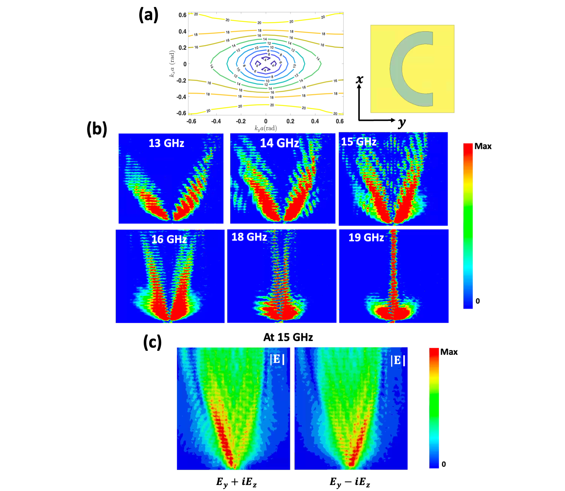
Fig.1 presents a schematic showing the C-shaped metasurface design we will study throughout this section. As depicted in Fig.1(b), the unit cell consists of a metallic C-shaped of 0.143mm thickness placed on a Roger’s 5880 substrate (). The C-shape metallic post has a width of 0.715mm and radius of 2.145mm where its edge is extended from the center by 0.429mm. The whole surface is 250mm250mm. The C-shape metasurface design was studied and optimized numerically using Ansys HFSS. In this section, we will explore different surface wave properties supported by the C-shaped metasurface through studying its equifrequency contours.
II.1 Self-Collimation
Isoropic shapes with small or no asymmetry have EFC close to a circle where the wave propagates equally in all direction. As the asymmetry of the shape increases, the contour becomes flatter with higher wave directionality and hence, higher self-collimation [33]. The C-shape design has broken rotational symmetry along the z- and x-axes which makes it a low-symmetry shape and hence, have high self-collimation. This can be observed from the calculated EFC of the C-shape unit cell shown in Fig.2(a). It can be shown that the C-shape design possesses different contour shapes which dictate various wave propagation properties. At 14 GHz, the EFC is elliptical which then becomes flatter at higher frequencies where high self-collimation takes place. The E-field profiles at different frequency contours are shown in Fig.2(b) where the surface is excited with an dipole at the bottom center. The magnitude of maps are calculated for each EFC. It can be observed that the wave is split where the split angle decreases with the increase of frequency. At 19 GHz, the surface wave is highly collimated as well as spin-independent. This means that any polarization will excite the wave to propagate with high collimation and zero split angle.
II.2 Spin-dependent Propagation
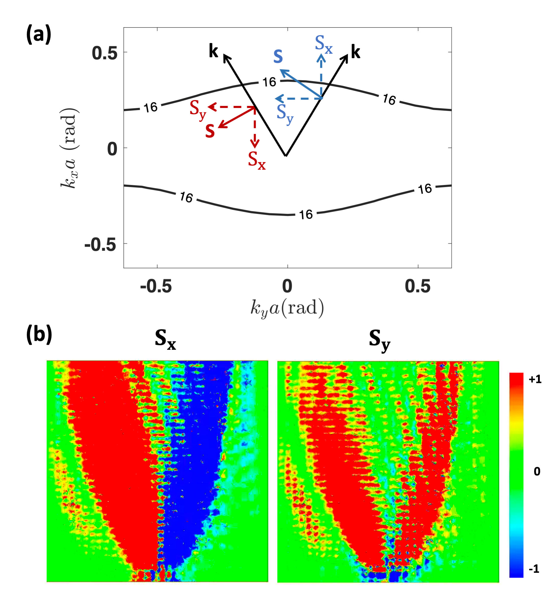
Fig.2(c) shows the spin-dependent behavior of the supported surface wave. The EFC calculated for the C-shape shows a spin-based wave splitting property where the wave is split into left-handed and right-handed circularly polarized waves. By excitation of the surface with an dipole source, the wave propagates along the left arm where it propagates along the right arm when excited with an dipole source. The spin density is defined as a vector quantity whose direction is normal to the plane of the field circular rotation. The following equation can be used to calculate the spin density of the propagating surface wave [34]:

| (1) |
where S is the spin density vector in Gaussian units normalized per one photon in units of . E and H are the electric and magnetic fields of the surface wave. Fig.3(a) shows a schematic representation of the two components of the transverse spin with respect to the two wave propagation directions where the component flips sign while the maintains the same sign for both wave propagation directions. Fig.3(b) shows the numerically calculated spin maps for the two split waves for and .
III Inhomogeneous Metasurface

As demonstrated, the EFC is closely related to the shape of the unit cell; engineering it can be done through different ways. For example, some studies showed that the change of the unit cell from square to rectangular or parallelogram can increase the flatness of the EFCs and hence increase the collimation [35, 36]. The symmetry of the shape itself can also result in changing the contour shape. For example, as described earlier, a broken rotational symmetry can produce flatter contours along the x- or y-axis. mirror symmetry of a shape can result in tilted contours [37].
In recent decades, there has been a great interest in gradient metasurfaces which are non-periodic surfaces aimed for wavefront manipulation for beam steering applications in near- or far-fields [38]. Such surfaces can be designed using ray optics approach [39], equivalence principle (Huygens metasurfaces) [40], geometric phase approach [41] or using programmable design generation [42]. Here, we present an alternative approach to design such surfaces by engineering EFCs. We show that we are able to steer the surface wave to propagate smoothly along specified curved paths using an inhomogeneous metasurface made of rotated C-shape unit cells. The inhomogeneous design is simply done by mapping the rotated C-shapes and their angle of collimation using the EFCs to form the specified wave path.
III.1 Rotation Angle and EFC
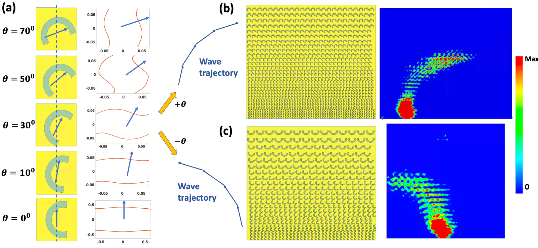
Fig.4(a) shows the design steps to make the inhomogeneous metasurface designs shown in Fig.4(b) and (c) through engineering the EFC. With a focus on the C-shape’s highly collimated EFC, it can be shown that rotating the C-shape unit cell results in rotating its EFC by almost the same angle of rotation, . For simplicity, we show schematics of five rotated unit cells at to and their corresponding EFCs. The blue arrows indicate the propagation direction of the wave. The wave trajectory deduced from the EFCs of the rotated C-shapes when using positive values can be shown in Fig.4(a), top right while the wave trajectory for using negative values where the wave is steered to the left is shown in Fig.4(a), bottom right.
Fig.4(b) and (c) show the inhomogeneous metasurface designs for the two wave paths described earlier. The design shown in Fig.4(b) is composed of 30 columns divided into 9 groups. In each group, is incremented by and the shape is scaled up by a scaling factor, . This is due to the fact that rotating the unit cell results in slight increase in its supported surface wave frequency. To eliminate the frequency mismatch, each rotated C-shape is scaled up by a scaling factor of 1.11. This scaling factor is deduced from mapping the rotation angles and its resulting frequency shift. The scaling factor, , of a unit cell can be defined in terms of its rotation angle as follows:
| (2) |

III.2 Surface Wave Steering
The E-field profiles for the two inhomogeneous metasurface designs at 19GHz are presented on the right in Fig.4(b) and (c) showing the smooth steering of the surface wave along curved paths. The demonstrated steered wave is spin-independent since we worked with the highly-collimated, spin-independent contour. This means that the same E-field profile can be achieved with a linearly or circularly polarized excitation source. This demonstrates how the EFC engineering for wave steering provides the capability of smoothly steering the surface wave along predetermined paths without much complexity in the designing process where the same unit cell design is used.
IV Experimental Results
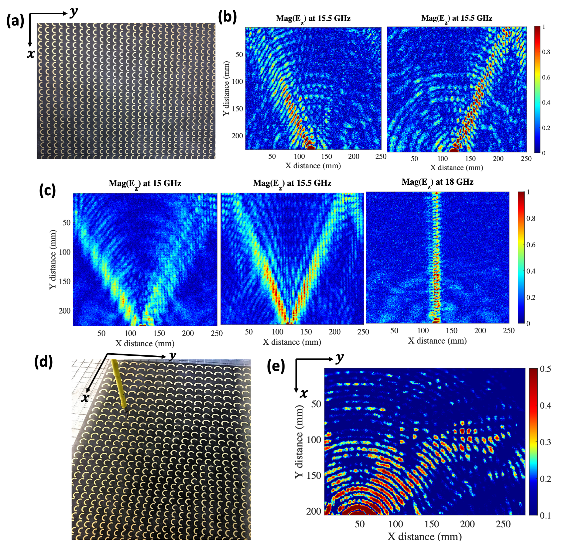
The C-shape metasurface was fabricated and measured. Fig.5(a) shows a photo of the fabricated homogeneous C-shape metasurface while the inhomogeneous surface is shown in Fig.5(d). The C-shape structures are made of copper which are placed on top of a Roger’s 5880 substrate of thickness 0.381mm. An probe used to excite the surface which is placed at the bottom center. Another measuring probe, is attached to a moving station which scans the surface point by point. Both probes are connected to Vector Network Analyzer (VNA) where the magnitude and phase of S21 are measured. The magnitude and phase of the can be extracted for the whole surface at different frequencies showing the different wave propagation properties as shown in Fig.5(b) which match the simulation results shown in Fig.2(b). The E-field profile shown on Fig.5(c) is measured for the homogeneous C-shape surface at 15.5GHz when excited with a circularly polarized (CP) dipole source. The CP dipole excitation is done through excitation with an and dipole sources separately and collecting the magnitude and phase of scan for each excitation. The two scans are then added with a phase shift using the following equation:
| (3) |
where is the measured when excited with a probe along -axis. The profile is measured for the inhomogeneous metasurface at 18.5GHz and shown in Fig.5(d) which demonstrates the surface wave steering along the predefined path.
V Conclusion
In this paper we studied numerically and experimentally a metallic C-shape metasurface design and its various wave propagation and polarization properties. We showed that due to the broken rotational symmetry of the C-shape design, it possesses high self-collimation. Additionally, we studied the spin-momentum locking phenomenon in the C-shape by calculating its spin density and showed it is capable of spin-dependent wave splitting. We also showed two inhomogeneous metasurface designs to steer the wave along defined curved paths by rotating the C-shape EFCs and scaling their sizes to eliminate frequency mismatch. This work emphasizes that engineering the EFCs can be simply done to achieve wide wave properties: spin-dependent wave splitting, highly confined waveguiding and wave steering along defined paths.
Acknowledgements.
This work is supported by the AFOSR under Grant No. FA9550-21-1-0167 as well as the ONR under Grant No. N00014-20-1-2710.References
- Yu and Capasso [2014] N. Yu and F. Capasso, Flat optics with designer metasurfaces, Nature materials 13, 139 (2014).
- Chen et al. [2020] W. T. Chen, A. Y. Zhu, and F. Capasso, Flat optics with dispersion-engineered metasurfaces, Nature Reviews Materials 5, 604 (2020).
- Yu et al. [2013] N. Yu, P. Genevet, F. Aieta, M. A. Kats, R. Blanchard, G. Aoust, J.-P. Tetienne, Z. Gaburro, and F. Capasso, Flat optics: controlling wavefronts with optical antenna metasurfaces, IEEE Journal of Selected Topics in Quantum Electronics 19, 4700423 (2013).
- Capasso [2018] F. Capasso, The future and promise of flat optics: a personal perspective, Nanophotonics 7, 953 (2018).
- Chen et al. [2016] H.-T. Chen, A. J. Taylor, and N. Yu, A review of metasurfaces: physics and applications, Reports on progress in physics 79, 076401 (2016).
- Li et al. [2018] A. Li, S. Singh, and D. Sievenpiper, Metasurfaces and their applications, Nanophotonics 7, 989 (2018).
- Quarfoth and Sievenpiper [2013] R. Quarfoth and D. Sievenpiper, Artificial tensor impedance surface waveguides, IEEE transactions on antennas and propagation 61, 3597 (2013).
- Dia’aaldin and Sievenpiper [2017] J. B. Dia’aaldin and D. F. Sievenpiper, Guiding waves along an infinitesimal line between impedance surfaces, Physical review letters 119, 106802 (2017).
- Lee and Sievenpiper [2016] J. Lee and D. F. Sievenpiper, Patterning technique for generating arbitrary anisotropic impedance surfaces, IEEE Transactions on Antennas and Propagation 64, 4725 (2016).
- Kuznetsov et al. [2015] S. A. Kuznetsov, M. A. Astafev, M. Beruete, and M. Navarro-Cía, Planar holographic metasurfaces for terahertz focusing, Scientific reports 5, 1 (2015).
- Ding et al. [2020a] F. Ding, Y. Chen, and S. I. Bozhevolnyi, Focused vortex-beam generation using gap-surface plasmon metasurfaces, Nanophotonics 9, 371 (2020a).
- Ding et al. [2020b] F. Ding, Y. Chen, and S. I. Bozhevolnyi, Gap-surface plasmon metasurfaces for linear-polarization conversion, focusing, and beam splitting, Photonics Research 8, 707 (2020b).
- Chen et al. [2021] X. Chen, H. Zou, M. Su, L. Tang, C. Wang, S. Chen, C. Su, and Y. Li, All-dielectric metasurface-based beam splitter with arbitrary splitting ratio, Nanomaterials 11, 1137 (2021).
- Yang et al. [2017] Y. Yang, L. Jing, L. Shen, Z. Wang, B. Zheng, H. Wang, E. Li, N.-H. Shen, T. Koschny, C. M. Soukoulis, et al., Hyperbolic spoof plasmonic metasurfaces, NPG Asia Materials 9, e428 (2017).
- Sievenpiper [2005] D. F. Sievenpiper, Forward and backward leaky wave radiation with large effective aperture from an electronically tunable textured surface, IEEE transactions on antennas and propagation 53, 236 (2005).
- Liu et al. [2020] W. Liu, H. Cheng, J. Tian, and S. Chen, Diffractive metalens: from fundamentals, practical applications to current trends, Advances in Physics: X 5, 1742584 (2020).
- Prather et al. [2007] D. W. Prather, S. Shi, J. Murakowski, G. J. Schneider, A. Sharkawy, C. Chen, B. Miao, and R. Martin, Self-collimation in photonic crystal structures: a new paradigm for applications and device development, Journal of Physics D: Applied Physics 40, 2635 (2007).
- Chuang [2010] Y.-C. Chuang, Complex photonic crystals for broadband “all-angle” self-collimation, Ph.D. thesis, The University of North Carolina at Charlotte (2010).
- Witzens et al. [2002] J. Witzens, M. Loncar, and A. Scherer, Self-collimation in planar photonic crystals, IEEE Journal of Selected Topics in Quantum Electronics 8, 1246 (2002).
- Bliokh and Nori [2012] K. Y. Bliokh and F. Nori, Transverse spin of a surface polariton, Physical review A 85, 061801 (2012).
- Bliokh et al. [2014] K. Y. Bliokh, A. Y. Bekshaev, and F. Nori, Extraordinary momentum and spin in evanescent waves, Nature communications 5, 1 (2014).
- Bliokh et al. [2015] K. Y. Bliokh, D. Smirnova, and F. Nori, Quantum spin hall effect of light, Science 348, 1448 (2015).
- Hirsch [1999] J. Hirsch, Spin hall effect, Physical review letters 83, 1834 (1999).
- O’connor et al. [2014] D. O’connor, P. Ginzburg, F. J. Rodríguez-Fortuño, G. A. Wurtz, and A. V. Zayats, Spin–orbit coupling in surface plasmon scattering by nanostructures, Nature communications 5, 1 (2014).
- Kandil and Sievenpiper [2021] S. M. Kandil and D. F. Sievenpiper, C-shaped chiral waveguide for spin-dependent unidirectional propagation, Applied Physics Letters 118, 101104 (2021).
- Lin et al. [2013] J. Lin, J. B. Mueller, Q. Wang, G. Yuan, N. Antoniou, X.-C. Yuan, and F. Capasso, Polarization-controlled tunable directional coupling of surface plasmon polaritons, Science 340, 331 (2013).
- Bisharat and Sievenpiper [2019] D. J. Bisharat and D. F. Sievenpiper, Electromagnetic-dual metasurfaces for topological states along a 1d interface, Laser & Photonics Reviews 13, 1900126 (2019).
- Ruan et al. [2020] W.-S. Ruan, X.-T. He, F.-L. Zhao, and J.-W. Dong, Analysis of unidirectional coupling in topological valley photonic crystal waveguides, Journal of Lightwave Technology 39, 889 (2020).
- Huang et al. [2013] L. Huang, X. Chen, B. Bai, Q. Tan, G. Jin, T. Zentgraf, and S. Zhang, Helicity dependent directional surface plasmon polariton excitation using a metasurface with interfacial phase discontinuity, Light: Science & Applications 2, e70 (2013).
- Picardi et al. [2017] M. F. Picardi, A. Manjavacas, A. V. Zayats, and F. J. Rodríguez-Fortuño, Unidirectional evanescent-wave coupling from circularly polarized electric and magnetic dipoles: An angular spectrum approach, Physical Review B 95, 245416 (2017).
- Picardi et al. [2018] M. F. Picardi, A. V. Zayats, and F. J. Rodríguez-Fortuño, Janus and huygens dipoles: Near-field directionality beyond spin-momentum locking, Physical review letters 120, 117402 (2018).
- Rodríguez-Fortuño et al. [2013] F. J. Rodríguez-Fortuño, G. Marino, P. Ginzburg, D. O’Connor, A. Martínez, G. A. Wurtz, and A. V. Zayats, Near-field interference for the unidirectional excitation of electromagnetic guided modes, Science 340, 328 (2013).
- Giden et al. [2013] I. H. Giden, M. Turduev, and H. Kurt, Broadband super-collimation with low-symmetric photonic crystal, Photonics and Nanostructures-Fundamentals and Applications 11, 132 (2013).
- Yermakov et al. [2016] Y. Yermakov, A. I. Ovcharenko, A. A. Bogdanov, I. V. Iorsh, K. Y. Bliokh, and Y. S. Kivshar, Spin control of light with hyperbolic metasurfaces, Physical Review B 94, 075446 (2016).
- Gao et al. [2008] D. Gao, Z. Zhou, and D. S. Citrin, Self-collimated waveguide bends and partial bandgap reflection of photonic crystals with parallelogram lattice, JOSA A 25, 791 (2008).
- Xu et al. [2008] Y. Xu, X.-J. Chen, S. Lan, Q. Guo, W. Hu, and L.-J. Wu, The all-angle self-collimating phenomenon in photonic crystals with rectangular symmetry, Journal of Optics A: Pure and Applied Optics 10, 085201 (2008).
- [37] S. M. Kandil, D. J. Bisharat, and D. F. Sievenpiper, Chiral surface wave propagation with anomalous spin-momentum locking, ACS Photonics .
- Estakhri and Alù [2016] N. M. Estakhri and A. Alù, Recent progress in gradient metasurfaces, JOSA B 33, A21 (2016).
- Yu et al. [2011] N. Yu, P. Genevet, M. A. Kats, F. Aieta, J.-P. Tetienne, F. Capasso, and Z. Gaburro, Light propagation with phase discontinuities: generalized laws of reflection and refraction, science 334, 333 (2011).
- Pfeiffer and Grbic [2013] C. Pfeiffer and A. Grbic, Metamaterial huygens’ surfaces: tailoring wave fronts with reflectionless sheets, Physical review letters 110, 197401 (2013).
- Berry [1987] M. V. Berry, The adiabatic phase and pancharatnam’s phase for polarized light, Journal of Modern Optics 34, 1401 (1987).
- Yang et al. [2016] H. Yang, X. Cao, F. Yang, J. Gao, S. Xu, M. Li, X. Chen, Y. Zhao, Y. Zheng, and S. Li, A programmable metasurface with dynamic polarization, scattering and focusing control, Scientific reports 6, 1 (2016).