RevaMp3D: Architecting the Processor Core and Cache Hierarchy
for Systems with Monolithically-Integrated Logic and Memory
Abstract
Recent nano-technological advances enable the Monolithic 3D (M3D) integration of multiple memory and logic layers in a single chip with fine-grained high-bandwidth connections. M3D technology leads to significantly higher main memory bandwidth and shorter latency than existing 3D-stacked systems. We show for a variety of workloads on a state-of-the-art M3D system that the performance and energy bottlenecks shift from main memory to the processor core and cache hierarchy. Hence, there is a need to revisit current core and cache designs that have been conventionally tailored to tackle the memory bottleneck. However, no prior work comprehensively examines the implications of M3D integration of logic and memory layers on the core and cache hierarchy design.
Our goal is to redesign the core and cache hierarchy, given the fundamentally new trade-offs of M3D technology, to benefit a wide range of workloads. To this end, we take two steps. In the first step, we perform a design space exploration of the cache hierarchy and core’s key components. Among the new observations, we highlight that in M3D systems, (i) removing the shared last-level cache leads to similar or larger performance benefits than increasing its size or reducing its latency; (ii) improving L1 latency has a large impact on improving performance; (iii) wider pipelines are increasingly beneficial since they can support a larger number of in-flight memory requests; (iv) the performance impact of branch speculation and pipeline frontend increases significantly due to the alleviated backend bottlenecks; (v) while high-bandwidth main memory facilitates running many threads, the current synchronization schemes limit parallel speedup. In the second step, we propose an optimized M3D system, RevaMp3D, leveraging two key features of M3D: (i) using the tight connectivity between logic layers, we efficiently increase pipeline width, reduce the L1 cache latency, and enable fine-grained synchronization; (ii) using the high-bandwidth and energy-efficient main memory, we alleviate the amplified energy and speculation bottlenecks of M3D systems by memoizing the repetitive fetched, decoded, and reordered instructions and turning off the relevant parts of the core pipeline when possible. RevaMp3D provides, on average, 81% speedup, 35% energy reduction, and 12.3% smaller area compared to the baseline M3D system.
1 Introduction
Recent nano-technological advances enable the Monolithic 3D (M3D) integration of multiple logic and memory layers on a single chip [1, 2, 3, 4, 5], which provides main memory bandwidth and latency benefits over conventional systems. M3D enables significantly higher main memory bandwidth compared to the state-of-the-art Through Silicon Via (TSV)-based 3D-stacked architectures (TSV3D) [6, 7, 4, 8] due to its much higher density of Inter-Layer Vias (ILVs) connecting different device layers. M3D enables lower main memory latency due to two key reasons. First, the high-bandwidth connection between device layers facilitates increasing the memory channel counts, which leads to (i) smaller array sizes with shorter wire lengths and (ii) and lower channel contention, both leading to lower average access latency. Second, the short and fast ILVs reduce the communication latency between the cores and main memory. For example, prior work [5, 9, 10] has demonstrated real M3D prototypes that provide 16 TB/s of memory bandwidth and 5ns/13ns average main memory read/write latency, which are an order of magnitude higher bandwidth and 10/4 lower read/write latency compared to the state-of-the-art TSV3D.
Due to its superior memory performance, M3D has received substantial interest in both academia and industry as a promising technology to address the memory bottleneck that significantly limits the performance and energy efficiency of modern data-intensive applications in conventional systems. Several prior works propose improvements for M3D systems, mainly focusing on three aspects. First, at the device level, several works [11, 12, 13, 14, 15, 16, 17, 18, 19, 20, 21, 22, 23, 24, 25, 26, 27, 28] propose circuit and device improvements to the logic and memory components and their integration in M3D substrates. Second, at the architecture level, some works [29, 30, 8, 31, 32, 33, 34, 35] propose M3D layout designs of processor components to reduce their wire length and latency. Other works [31, 22] explore the memory system challenges in M3D (e.g., designing main memory array structure and controllers). Third, at the application level, various works [36, 37, 38, 39, 40, 30, 41, 42] propose application-specific M3D accelerators.
While prior works propose various improvements for M3D-based systems, no prior work revisits the fundamental architectural design decisions for M3D systems with monolithically-integrated logic and main memory when running modern real-world applications. Given the opportunities to drastically improve memory performance in M3D, it is important to understand the implications of this technology on the performance and energy bottlenecks of real-world applications and architectural designs which have been conventionally specialized to tackle the main memory bottleneck. Based on our experimental motivational analysis of a variety of workloads on a state-of-the-art M3D system [5, 2, 3, 4], we make two key observations. First, compared to the 2D and TSV3D systems, the performance bottlenecks shift from main memory to the processor core and cache hierarchy (even for the memory-bound workloads) due to the high-bandwidth fast M3D main memory. Second, the processor core becomes the primary source of power consumption due to the energy-efficient M3D main memory (see Section 2).
Our goal in this work is to design the core and cache hierarchy given the fundamentally new trade-offs and the shifted bottlenecks in M3D technology. To this end, we take two steps. First, we explore the implications of M3D bottlenecks on system architecture. Second, we apply our insights from the first step and leverage the new opportunities of the M3D integration technology to design a new M3D system, RevaMp3D.
Implications of M3D Bottlenecks on Cache Hierarchy Design. Through detailed analysis of the depth, size, and latency of the cache hierarchy, we make three new observations. First, all workloads perform better or equally well in an M3D system with a shallow one-level cache hierarchy compared to an M3D system with a deeper and larger cache hierarchy (Section 5.1.1). The reason is that removing deeper cache levels eliminates the additional cache access latency from an already fast memory access time in M3D. Second, even after applying the unique optimizations enabled by M3D to improve cache performance and capacity, the performance benefit of removing the deeper cache levels is higher than or comparable to increasing their size (Section 5.1.2) and improving their latency (Section 5.1.3). Third, improving the L1 cache latency improves performance for a wide range of workloads (Section 5.1.3) due to the large effect of L1 latency on average memory access time in M3D.
Implications of M3D Bottlenecks on Processor Core Design. To analyze the implications of M3D bottlenecks on the processor core, we evaluate the performance impact of different units in all stages of the processor pipeline on the M3D system. We make three new observations, highlighting the most important factors contributing to the performance. First, larger pipeline widths are very effective at improving M3D’s performance since an M3D system can tolerate more in-flight memory accesses due to its high memory bandwidth (Section 5.2.1). Second, the performance impact of branch speculation and pipeline frontend increases significantly (Section 5.2.2). The reason is that memory bottleneck is significantly alleviated in M3D and the fraction of execution time spent on other bottlenecks such as speculation and frontend increases. Third, while high-bandwidth main memory enables running many threads, the current synchronization schemes limit performance (Section 5.2.4).
Re-Architecting M3D. By applying the insights from the first step, in this step we propose an optimized M3D system, RevaMp3D. To this end, we leverage two key features of the M3D technology: (i) the dense inter-layer connectivity between different logic layers, and (ii) high-bandwidth and energy-efficient main memory.
We make four design decisions. First, we reduce L1 cache latency by dividing the SRAM array into two logic layers to reduce its overall wire length. Second, we increase pipeline width, without incurring additional latency overhead. This is because similar to L1, we devise a vertical M3D layout for the storage structures in the pipeline to keep their wire lengths short. The first two optimizations take advantage of the dense ILVs that enable efficient vertical layouts of the processor structures [29, 30, 8, 32, 33, 34, 35]. Third, we propose a register file-level synchronization technique for fine-grained inter-thread communication, without incurring additional latency in the memory hierarchy. This technique is realized by using the thin ILVs to efficiently increase the register file bandwidth to support both the baseline core and the synchronization-related accesses. Fourth, we use main memory to memoize the fetched, decoded, and reordered instructions. This optimization (i) alleviates energy bottlenecks by turning off the decoding, fetching, and reordering structures of the pipeline when repeated instructions execute, and (ii) alleviates branch misspeculation overhead by reducing the number of pipeline bubbles since a large fraction of instructions do not need to be fetched, decoded, and re-ordered in the event of misspeculation. This technique is enabled by the high-bandwidth and energy-efficient M3D main memory, and eliminates the area overhead of prior works that propose instruction memoization in large SRAM caches[43, 44].
Key Results. To evaluate RevaMp3D, we use a cycle-accurate architectural simulator (ZSim [45]) to flexibly explore various designs and faithfully model the M3D systems. The parameters for the M3D baseline are experimentally-calibrated by the fabricated device models, circuit analysis, interconnect model, and physical design tools presented in [5]. On systems with 1, 16, 64, and 128 cores, RevaMp3D provides on average 81% performance improvement and 35% energy reduction across all workloads and core counts, with a 12.3% reduction in logic area, compared to the state-of-the-art M3D system.
As part of our large-scale design space exploration in this work, we analyze the impact of RevaMp3D’s design decisions for M3D systems with various main memory latency values. We find memory latency to be particularly important since while prior work has demonstrated the low memory latency (e.g., 5 ns for read) of M3D systems using a hardware prototype [5], the memory latency can vary depending on the design decisions made to meet certain requirements of the target M3D system. Our analysis demonstrates that the benefits of some design decisions (e.g., register-file synchronization) increase for larger latency values, while the benefits of some others (e.g., trading off cache area to increase pipeline width) decrease. This analysis facilitates picking the right design decisions based on the M3D main memory latency.
We conclude that by re-architecting the M3D system based on its shifted bottlenecks and new trade-offs and opportunities we can more effectively allocate the logic area to improve performance for a wide range of workloads.
This work makes the following key contributions:
-
To our knowledge, this is the first work to redesign core and cache hierarchy for a general-purpose M3D system based on rigorous bottleneck analysis of a wide range of real-world workloads, and exploring the architectural implications of these new bottlenecks.
-
We show that in M3D, the application bottlenecks shift from main memory to other parts of the system.
-
We conduct a design space exploration of key components of the processor core and cache hierarchy to enable architecting general-purpose M3D systems.
-
We design RevaMp3D based on our insights and leveraging M3D’s key opportunities: (i) tightly-integrated logic layers and (ii) fast and energy-efficient main memory. RevaMp3D provides significant performance improvement and energy reduction compared to the state-of-the-art M3D system at lower area cost.
2 M3D Technology
We provide a brief overview of the M3D integration technology, state-of-the-art M3D systems, and their technology feasibility and constraints.
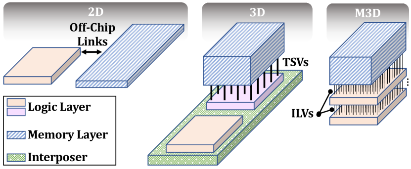
M3D Integration Technology. There has been significant effort into enabling tighter integration of logic and memory units in the system to improve performance and energy. Figure 1 compares three different systems. In 2D systems, computation and memory units are connected via off-chip links with low bandwidth, which is imposed by the limited number of I/O pins in the memory system. In 3D systems [46, 47, 48, 49, 50, 51, 52, 53, 54], memory layers are connected using Through-Silicon Vias (TSVs) and can be connected to logic units directly below the memory layers using TSVs or on an interposer substrate. Compared to 2D systems, 3D systems provide higher main memory bandwidth, lower latency, and better energy-efficiency. In M3D systems [5, 8], logic and memory layers are monolithicly fabricated on the same chip with a large number of thin Inter-Layer Vias (ILVs) with 40 nm to 80 nm diameter [5, 8]. Compared to TSVs, which have a diameter of 2.6m [8] to 5m [55], the smaller diameter of ILVs enables a much higher density of connections between adjacent layers of an M3D system. Due to its smaller diameter, ILV has lower area overhead, higher flexibility in placement, lower capacitance, and requires lower power to drive compared to TSVs [8].
There are two classes of M3D systems: M3D systems that consist of (i) only logic layers; and (ii) both logic and memory layers. The M3D systems of the first type provide several performance optimization opportunities, such as efficient 3D partitioning of logic structures (cores, caches, NoCs) in M3D to reduce their latency by shortening the wire lengths [29, 8]. M3D systems of the second type enable benefits in addition to the first type by integrating both memory and logic layers on the same chip and significantly alleviating the main memory bottlenecks. In this work, we consider M3D systems with both memory and logic layers.
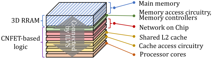
State-of-the-Art Architecture. We use N3XT [4, 5, 3, 2], a state-of-the-art M3D architecture, as our M3D baseline. N3XT [4, 5, 3, 2] architecture monolithically integrates logic and memory in the same chip, while leveraging energy-efficient emerging technologies such as latency-optimized monolithic 3D RRAM arrays as main memory [9, 10] and carbon-nanotube-based transistors in the logic layer [1, 2, 3]. Figure 2 shows a baseline M3D architecture [5], integrating several logic and memory layers: a logic layer for processor cores, a logic layer for cache access circuitry, a layer for a shared L2 cache (which can be fabricated either as SRAMs or STT-MRAMs), two logic layers for network on chip to enable high-bandwidth communication between the high-bandwidth main memory and the processor cores, a logic layer for memory access circuitry and memory controllers, and 64 RRAM layers.
N3XT [5] achieves both high-bandwidth and low-latency memory accesses via integrating emerging logic and memory layers on the same chip. High bandwidth is realized by the dense ILV connectivity [5, 9, 46, 47, 48, 49, 50, 51, 52, 53, 54]. N3XT achieves low average read/write latency due to three reasons [5]. First, due to high bandwidth between different device layers, M3D system employs a large number of channels that are connected to small memory arrays. Small arrays lead to smaller wire lengths, which directly affect latency. Second, sensing mechanism are faster in N3XT due to the faster switching rates of the transistors used and the larger drive current provided by the access transistors. Third, short and dense ILVs lead to (i) low-latency interconnection between logic and memory on the same chip and (ii) low contention overheads even when a large number of cores access memory concurrently. N3XT provides 10/4 lower average memory latency compared to the state-of-the-art TSV3D systems [56, 6].
Technology Feasibility and Constraints. The fabrication and thermal feasibility of the N3XT architecture has been demonstrated by real prototypes [3]. Recent advancements enable fabrication of M3D technology using commercial silicon manufacturing facilities [57]. Prior work shows that both logic and RRAM layers can be fabricated at low temperature (300∘C [5]), paving the way to monolithically fabricate layers without melting bottom layers. Despite all the benefits, the RRAM-based main memory has limited write endurance. Prior works address this issue using online data relocation wear-leveling, extending the device lifetime to at least 10 years [5]. We consider the same solution for our baseline (Section 3).
3 Methodology
3.1 Workloads
| Class | Workload | Suite | Domain | Input Size (MB) | BE(%) | Mem (%) | BW (%) | ILP | LFMR |
|---|---|---|---|---|---|---|---|---|---|
| Bandwidth-bound | YOLO | Darknet [58] | Machine Learning | 204 | 94.17 | 62.01 | 56.60 | 2.25 | 0.99 |
| BFS | Ligra [59] | Graph Processing | 2017 | 44.94 | 59.14 | 40.56 | 1.71 | 0.98 | |
| BC | Ligra [59] | Graph Processing | 2017 | 75.72 | 65.16 | 56.84 | 2.09 | 0.99 | |
| KCore | Ligra [59] | Graph Processing | 2017 | 94.54 | 44.88 | 78.68 | 1.62 | 0.99 | |
| MIS | Ligra [59] | Graph Processing | 2017 | 86.70 | 71.72 | 90.88 | 2.02 | 0.99 | |
| PageRank | Ligra [59] | Graph Processing | 2017 | 86.70 | 71.72 | 90.88 | 2.02 | 0.99 | |
| Radii | Ligra [59] | Graph Processing | 2017 | 54.12 | 43.10 | 66.34 | 1.78 | 0.99 | |
| Copy | STREAM [60] | Benchmarking | 3200 | 80.94 | 73.98 | 88.54 | 2.25 | 1 | |
| Latency-bound | StreamCluster | Rodinia [61] | Data Mining | 67 | 63.84 | 43.22 | 17.38 | 1.74 | 0.99 |
| ResNet | Darknet [58] | Machine Learning | 230 | 62.66 | 55.00 | 26.74 | 2.25 | 0.99 | |
| Oceanncp | Splash-2 [62] | HPC | 17 | 92.98 | 47.02 | 22.12 | 6.63 | 1 | |
| Components | Ligra [59] | Graph Processing | 2017 | 50.94 | 42.12 | 6.62 | 1.38 | 0.99 | |
| Triangle | Ligra [59] | Graph Processing | 2017 | 62.08 | 51.10 | 18.74 | 1.41 | 0.99 | |
| Myocyte | Rodinia [61] | Simulation | 364 | 93.44 | 89.26 | 29.92 | 1.88 | 0.99 | |
| Compute-bound | 3mm | PolyBench [63] | Linear Algebra | 128 | 60.3 | 13.8 | 34.68 | 2.75 | 0.61 |
| 2mm | PolyBench [63] | Linear Algebra | 128 | 62.50 | 13.8 | 35.29 | 2.55 | 0.60 | |
| atax | PolyBench [63] | Linear Algebra | 512 | 25.50 | 1.60 | 14.9 | 2.37 | 0.51 | |
| gemm | PolyBench [63] | Linear Algebra | 96 | 63.4 | 13.8 | 23.11 | 2.55 | 0.58 | |
| ferret | PARSEC [64] | Similarity Search | 47 | 29.22 | 4.5 | 0.5 | 2.64 | 0.61 | |
| Needleman-Wunsch | Rodinia [61] | Bioinformatics | 4295 | 79.96 | 39.66 | 65.46 | 2.35 | 0.52 |
Table 1 summarizes the multi-threaded workloads used in our analysis and evaluation. Our selected workloads are from various domains and pressure different parts of the system.
To gain an initial understanding of the primary sources of bottlenecks for our workloads, we perform a top-down analysis [65], a widely-adopted workload-characterization approach that hierarchically characterizes the bottlenecks of a workload [65, 66, 67, 68]. We use the Intel VTune Amplifier [69] to perform the top-down analysis for all workloads listed in Table 1, while running on Intel Xeon E3-1240 processor with 4 cores. We classify the workloads into three categories: bandwidth-bound, latency-bound, and compute-bound. Table 1 shows the backend-bound (BE), DRAM-bound (Mem), and DRAM bandwidth-bound (BW) values for each workload. Backend-bound (BE) accounts for the percentage of a workload’s execution time during which the processor cannot issue new instructions due to stalls at the pipeline backend, including stalls due to memory requests (characterized as memory-bound) and core execution (e.g., no empty free slot in the execution unit of the pipeline, characterized as compute-bound). The memory-bound divides into cache-bound and DRAM-bound, where DRAM-bound can be further split into DRAM latency- and bandwidth-bound. Based on our characterization, we categorize the workloads with large BE (40%), Mem (40%), and BW (50%) as DRAM bandwidth-bound since we observe large performance improvements when improving the main memory bandwidth for these workloads. Workloads with high BE and Mem and low BW are classified as DRAM latency-bound since we observe large performance improvements when improving the main memory latency for these workloads. Workloads with high BE and low Mem are classified as compute-bound.
Table 1 also shows instruction-level parallelism (ILP) [70] and Last-to-First Miss Ratio (LFMR) [71], which we obtain by dividing the number of LLC misses by the L1 misses. A high LFMR value suggests that (i) not only the LLC but also any cache between the first and the last levels does not provide significant benefits in reducing the miss-rate, and (ii) the workload does not benefit from a deep cache hierarchy. We show the LFMR between the L1 and L2 (the last-level cache in M3D). We consider LFMR values above 90% as high, as most memory requests are not serviced by L2.
3.2 Experimental Setup
| System | M3D | 3D | 2D | |||||||||||||
|---|---|---|---|---|---|---|---|---|---|---|---|---|---|---|---|---|
| Main memory |
|
|
|
|||||||||||||
| L3 | None | None |
|
|||||||||||||
| L2 |
|
|
|
|||||||||||||
| L1 |
|
|||||||||||||||
| Processor core |
|
|||||||||||||||
We provide details about the modeled systems, and cache, core , and main memory considerations.
Modeled Systems. We use a cycle-accurate architectural simulator (ZSim [45]) to flexibly explore various designs and faithfully model the following systems:
-
2D: a system based on the 2D integration of computation and memory, where the computing elements and main memory (DRAM) communicate through an off-chip bus.
-
M3D: a system based on N3XT [5], where memory and logic are monolithically fabricated on each other, with an order of magnitude higher main memory bandwidth and 10x/4x lower read/write latency than 3D.
The parameters for M3D are experimentally-calibrated by the fabricated device models, circuit analysis, interconnect model, and physical design tools presented in [5]. We summarize all system parameters in Table 2.111The main memory latency values in this table refer to average main memory access latency. We also analyze the design tradeoffs for M3D systems with various main memory latency values in Section 7.4. We also show the configurations analyzed in Section 5 in parenthesis for each element.
Cache and Core. In our analysis, we initially consider the same core and L1 caches for all configurations. The 2D configuration has a deeper and larger cache hierarchy compared to the TSV3D and M3D designs since it has the lowest available memory bandwidth and the longest memory access latency. We consider a cache hierarchy for M3D similar to N3XT [5] (private L1 and shared L2). We consider the same cache hierarchy for TSV3D. In Section 5, we study the effects of different cache sizes and core configurations on M3D’s performance.
Main Memory. We assume all three systems have large enough main memory capacity to house applications’ dataset in our experiments.222We also discuss the scenario where the entire dataset does not fit in one M3D stack in Section 8. Although the main memory in our M3D baseline is RRAM-based and different from the DRAM used in 2D and TSV3D, in our performance analysis, we primarily distinguish the memories of different systems by their bandwidth and latency, and not other device features. Despite its benefits, M3D memory has reliability issues and limited endurance, which is alleviated in our baseline with prior techniques (see Section 2). Our M3D baseline uses RRAM main memory due to its larger density compared to other technologies feasible for M3D integration (e.g., STT-MRAM) [5]. We also evaluate the performance of a potential M3D system with STT-MRAM main memory in Section 6, but we leave further exploration of other memory technologies as future work.
Network on Chip. Our M3D baseline[5] uses the meshes of trees (MoT) [77] scheme to provide a high-bandwidth connection between the cores and the memory controllers. This network supports uniform memory access (UMA) such that each core has the same access latency to any main memory location. This incurs additional multiplexing cost, but the M3D baseline amortizes this cost through improved inter-layer connectivity. As shown by prior works [77], MoT networks are highly scalable in terms of contention. While the number of network links increases when increasing the number of cores, the planar logic area dedicated to the network layers (Figure 2) also increases and enables containing the larger network. As the network size increases, we consider the effect of larger hop counts in the MoT network on the end-to-end memory access time in our evaluations.
4 Motivational Studies
We conduct an experimental analysis of a variety of workloads on a state-of-the-art M3D system to understand how M3D impacts their performance and energy bottlenecks compared to conventional 2D and 3D technologies.
4.1 Performance Bottlenecks
The optimizations in M3D’s memory system leads to significant performance improvements for our workloads in Table 1 (on average 2.82 and up to 9.02, compared to the 3D system). We compare the performance bottlenecks of memory latency-/bandwidth-bound workloads to show how M3D affects the performance bottlenecks. We extend ZSim [45] by incorporating the top-down bottleneck analysis [65]. We validate our implementation of the top-down analysis in ZSim by comparing its output against Intel VTune Amplifier [69] running on Intel Xeon E3-1240. Our validation shows that the ZSim-based top-down analysis identifies very similar trends in bottlenecks as Intel Vtune [69], showing high Pearson correlation value [78] of 93.94% () across our workloads with various behavior. Our model shows, on average, a 19% higher absolute value for the backend bottleneck than VTune but well fits the requirements of our bottleneck analysis since we focuses on the trends of backend bottlenecks across different systems.
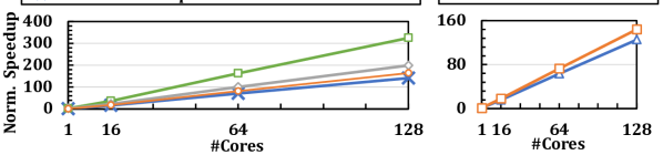
Figure 3 shows the top-down bottleneck breakdown of a representative latency-bound workload, Triangle, when running on different systems (i.e., 2D, 3D, M3D) and core counts (1/16/64/128). We make three key observations. First, M3D improves the performance333Performance refers to the normalized parallel speedup, where all values are normalized against that of the 2D baseline with 1 core. over the 2D and 3D baselines by up to 6.82 and 1.47, respectively, across all core counts (1/16/64/128). Second, in the M3D system, we observe a large average reduction in the ratio of execution time spent on the backend, compared to the 2D and 3D systems (1.87 and 1.52, respectively). In this case, we observe a bottleneck shift in the system from backend to frontend and speculation. To further understand the main memory contribution to the backend bottleneck, we study an idealized M3D system with one cycle main memory latency and no main memory bandwidth bottleneck. 444Alleviating the main memory bandwidth bottleneck is modeled with a configuration in which the performance of the application is not bottlenecked by the limited main memory bandwidth. We do not change load/store queues or cache hierarchy in this case. We observe that even such a configuration only improves the performance by 7%, which means that the main memory is not a key contributor to M3D backend bottleneck. Since the main memory bottleneck is alleviated in M3D, other sources of the backend bottleneck dominate the backend bottleneck, such as cache hierarchy, and the processor core’s backend (e.g., execution ports) [69].
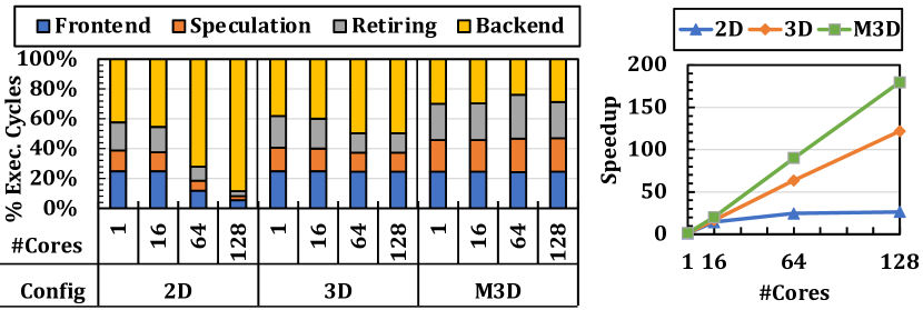
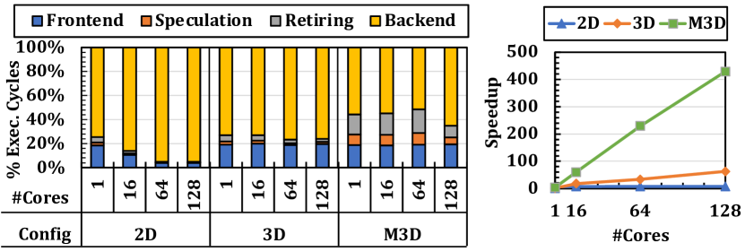
Figure 4 shows the top-down bottleneck breakdown of a representative bandwidth-bound workload, BFS. We make three key observations. First, M3D improves the performance over the 2D and 3D baselines up to 39.63 and 4.80 across all core counts, respectively. Second, in the M3D system, we observe 1.57 and 1.37 reductions in the ratio of execution time spent on backend compared to the 2D and 3D systems, respectively. Third, reducing the main memory latency to one cycle and eliminating all bandwidth bottlenecks only leads to a 23% performance improvement, lowering the backend bottleneck only by 5%, indicating that memory is not a key contributor to the backend. We conclude that these advancements results in the shifting of application bottlenecks from main memory to other parts of the system.
4.2 Energy Bottlenecks
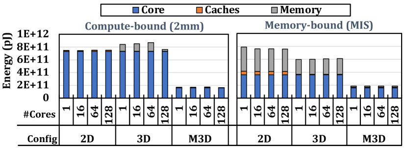
We study the energy bottlenecks in M3D. Figure 5 shows the energy breakdown of representative memory-bound (MIS) and compute-bound (2mm) workloads, respectively, on 2D, 3D, and M3D systems with 1/16/64/128 cores. We make two key observations. First, compared to 2D (3D) baseline, M3D consumes on average 4.32 (4.76) and 4.13 (3.32) lower energy on compute-bound and memory-bound workloads, respectively. Second, even though for the memory-bound workloads, the main memory consumes a significant percentage of the overall energy in 2D and 3D systems, the main memory in M3D baseline contributes to only 12% of the energy on average due to its low cost per bit (Table 1), which is enabled by three factors. First, our M3D baseline employs RRAM-based main memory that is more energy-efficient compared to DRAM [3, 4, 5]. Second, main memory access circuits are built using CNFETs that consume less power compared to MOSFETs [1]. Third, M3D uses ILVs to transfer data back and forth between the main memory and the logic layers that have lower energy consumption compared to TSVs in 3D designs and off-chip links in 2D designs [3, 4, 5]. We conclude that, in the M3D system, the core turns into the most important energy bottleneck.
4.3 Our Goal
Given the opportunities provided by M3D to drastically shift the performance and energy bottlenecks, it is important to understand the implications of this new technology on architectural designs which have been conventionally specialized to tackle the memory bottleneck. Our goal is to redesign the core and cache hierarchy given the new trade-offs of M3D technology. While in this work, we focus on architecting M3D systems, we argue that if future TSV-based systems (3D/2.5D) achieve the same bandwidth and latency as current M3D devices, our architecture insights can also be applied to such systems.
5 Architecting the Processor Components
To adapt the general purpose processors to the opportunities and bottlenecks of M3D systems, we analyze the design trade-offs of the cache hierarchy (Section 5.1) and the cores (Section 5.2) in a general-purpose M3D system. Table 3 summarizes (i) the key structures in different pipeline stages studied in this work, (ii) the key analyzed aspect of each structure, and (iii) a pointer (Ptr.) to the relevant sections.
| Stage | Key structure | Studied aspect | Ptr. | |||||||||
|---|---|---|---|---|---|---|---|---|---|---|---|---|
| Fetch |
|
|
|
|||||||||
| Decode |
|
|
|
|||||||||
| OoO | Instruction window | Part of pipeline width | Section 5.2.1 | |||||||||
| Structure | Reorder buffer | Reorder buffer size | Section 5.2.3 | |||||||||
| Execution | Functional units |
|
|
|||||||||
| Memory |
|
|
|
|||||||||
| Writeback | Register file | Read/write ports | Section 5.2.1 |
5.1 Cache Hierarchy
The design space of the cache hierarchy in M3D is affected by two conflicting factors; (i) the M3D technology enables improving the capacity and latency of caches through device/circuit improvements [32, 33, 34, 35]; and (ii) the M3D main memory significantly alleviates the main memory bottleneck. We evaluate the impact of the depth, size, and latency of the cache hierarchy given these trade-offs.
5.1.1 Depth of the Cache Hierarchy
To study the implications of M3D on the depth of the cache hierarchy, we compare (i) noL2, an M3D system with no L2 cache555Coherency is still maintained using a shared directory., and (ii) w/L2, with a shared L2 cache of 256 KB per core.
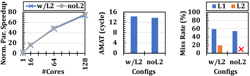
Workloads with Low LFMR. Figure 6 shows the performance of a representative workload with low LFMR (atax) across all core counts, alongside the Average Memory Access Time (AMAT), and cache miss rates for a 64-core system. We make three observations. First, despite having a low L2 cache miss rate of 19% in the w/L2 configuration and the faster L2 accesses compared to the M3D main memory accesses, removing the L2 cache does not hurt the performance. Second, we observe that the AMAT in the noL2 configuration is on par (even 4% lower) with the AMAT in the w/L2 configuration. While removing the L2 cache does not significantly hurt AMAT for workloads with high L2 hit rates in M3D, removing it in the 3D baseline can lead to an up to 17 larger AMAT due to its slower main memory.
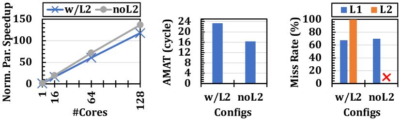
Workloads with High LFMR. Figure 7 shows the performance, AMAT, and cache miss rates of a representative workload with high LFMR (MIS) for the same configurations. Based on this figure, we make three observations. First, noL2 improves performance by 17.8% on average across all core counts compared to both configurations with L2. Second, the L2 cache is highly ineffective (99% misses) in filtering accesses to main memory. Third, the AMAT in the noL2 configuration is significantly lower than the two other configurations since it does not add extra L2 access latency and contention overhead.
We conclude that due to low access latency of M3D main memory, removing the shared last level L2 cache does not hurt performance for workloads with both low and high LFMR. In fact, removing the L2 cache leads to even 10% average speedup across all workloads. Specifically, for bandwidth-bound workloads with high LFMR, removing L2 also increases the performance scalability due to reduced cache contention when the core count increases. We observe on average 8%/8%/12%/18% speedups for 1/16/64/128-core configurations compared to the M3D baseline.
Lifetime Implications. While removing the shared caches increases the number of accesses to main memory, the baseline provisions for lifetime guarantees in the M3D baseline are already sufficient for the scenario where L2 is removed. This is because the baseline device should already be designed for the worst case scenario where the caches are not effective in filtering main memory accesses (a common scenario for memory-bound workloads). We observed that caches were not effective in filtering main memory accesses for memory-bound workloads, and removing caches does not change the overall number of main memory accesses. For compute-bound workloads, the number of memory accesses increases after removing shared caches, but these workloads have a relatively smaller number of main memory accesses compared to memory-bound workloads. Therefore the baseline provisions for lifetime should already be sufficient.
5.1.2 Impact of Cache Size
In this section, we study the performance implication of increasing the L2 cache size in M3D systems. M3D facilitates circuit-level and device-level optimizations to increase cache size or reduce cache latency via (i) using vertical layout of SRAM arrays to reduce the overall wire lengths [8] or (ii) monolithic integration of emerging technologies such as STT-MRAM as large and energy-efficient caches [4, 5, 16, 3]. Analyzing the effects of such optimizations on the end-to-end performance of M3D systems with logic and memory layers enables us to decide whether removing L2 in such systems is ultimately better than optimizing it with unique capabilities of M3D integration. We analyze the performance of workloads with low and high LFRM, with L2 sizes of 256KB fixed, 256KB per core, 1/8/64 MB fixed, and without L2. We assume the same number of cache banks in the configurations with L2. Even though increasing cache size can increase latency, we conservatively consider the ideal case where the latency does not increase with the cache size.
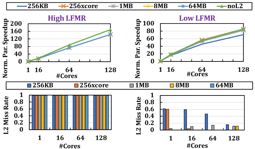
Figure 8 shows performance and L2 cache miss rate for a representative workload with high LFMR (PageRank) and low LFMR (2mm). We make three observations. First, larger caches improve the performance of the low-LFMR workload by up to 22.7% compared to 256KB. Second, despite the benefits of larger L2 for low-LFMR workloads, the performance of noL2 is similar to the performance of the configurations with a larger L2 size (64MB outperforms noL2 only by 3%), while incurring significantly less area overhead than the 64MB configuration. Third, increasing the cache size does not improve performance for high-LFMR workloads (all configurations with L2 have the same performance). This is because increasing the cache size does not reduce the cache miss rates. On average across all workloads with different core counts, increasing the cache size leads to only 3.7% performance improvement compared to the baseline M3D system. Even for workloads with low LFMR, increasing the cache size leads to only 2% higher average performance benefit compared to removing L2. We conclude that in M3D, a larger L2 cache does not lead to significantly better performance compared to removing L2.
5.1.3 Impact of Cache Latency
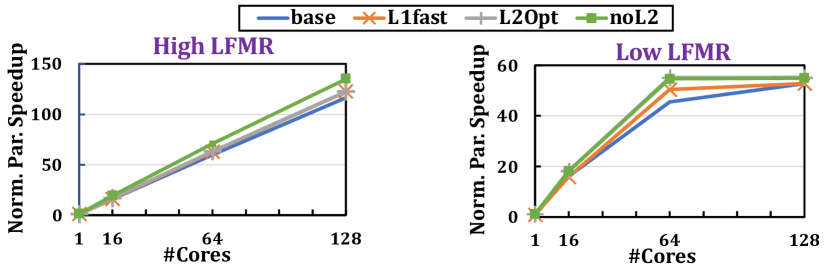
We study the effect of reducing the latency of L1 and L2 caches on the overall performance of M3D. We analyze M3D system configurations where (i) the L1 latency is 2 faster than that of the baseline (L1fast), and (ii) the L2 latency is 2 faster than the baseline’s, and the L2 size is 64MB (L2Opt), modeling an idealized high-density and fast monolithic cache. Figure 9 shows the performance effect of the mentioned cache configurations on representative workloads with high LFMR (MIS) and low LFMR (3mm). We make three observations. First, L2Opt improves performance by 5% compared to base for the high-LFMR workload, while removing the L2 cache outperforms the L2Opt case by 11% due to the high L2 miss rate of 99% in L2Opt. Second, for the low-LFMR workload, we also do not observe significant benefits in improving L2 latency compared to noL2. Third, for the high- and low-LFMR workloads, improving the L1 cache access latency leads to 5% and 10% performance improvements compared to base for high- and low-LFMR workloads, respectively. This is because L1 cache latency represents a large portion of the AMAT in M3D due to M3D’s fast main memory, and improving L1 access latency has a large impact on AMAT. Overall, we observe an on-average 12.5%/6% speedup from L1/L2 latency reduction, across all workloads. We conclude that removing the shared L2 cache leads to better or comparable performance improvement compared to larger or faster L2 caches. However, it is still important to reduce L1 cache latency in M3D.
While different cache array organization, configurations, and replacement policies can improve performance benefits of the L2 cache for some workloads, we argue that removing the L2 cache in the baseline M3D configuration provides equal or more benefits than such optimizations for L2. This is due to two reasons. First, some classes of optimizations lead to increased cache hit rate. However, in Figure 6, we show that even the performance of a workload with very high L2 cache hit rate does not significantly exacerbate when removing the L2 cache. Second, some classes of optimizations lead to reduced L2 cache access latency. However, in Figure 9, we show that reducing the L2 cache access latency even for a workload with high cache hit rate does not significantly outperform the configuration without the L2 cache.
5.2 Processor Core Design
We analyze various aspects of the core’s pipeline for M3D in detail, as described in Table 3.
5.2.1 Impact of Pipeline Width
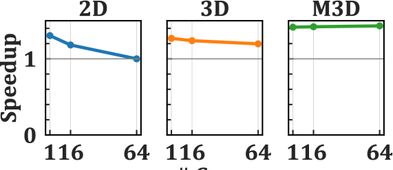
We aim to understand the performance impact of higher in-flight requests in M3D systems by studying the impact of wider pipelines in M3D, in comparison to its effect on 2D and 3D systems. Wider pipelines lead to a higher number of in-flight requests, which can be beneficial when the processor’s backend can serve requests efficiently. Figure 11 compares the speed up in 2D, 3D, and M3D systems when doubling the pipeline width for a bandwidth-bound workload (BFS). Each data point is the speedup of each configuration after widening the pipeline over the same configuration. We make two observations. First, doubling the pipeline width provides a 40% speedup in the M3D system. Second, we do not observe similar performance improvements from increasing the pipeline width in the 2D and 3D systems for this bandwidth-bound workload. With large core counts, main memory bandwidth becomes the major performance bottleneck in the 2D and 3D systems and cannot service a higher number of in-flight memory requests from the wide pipeline. Across all workloads in Table 1, we observe a 16% performance improvement on average across all core counts (1, 16, 64, 128). For compute-bound workloads with higher ILP among our workloads, we observe an on-average 28% speedup across all core counts. We conclude that wider pipelines provide relatively higher performance benefits to M3D compared to 2D and 3D systems.

Width of Individual Pipeline Stages. We analyze the effects of increasing the widths of different pipeline stages to understand whether significant benefits are obtained by selectively increasing the widths of only parts of pipeline at lower area cost. We evaluate (i) the M3D system with 2 read/write ports for the register file, and (ii) the isolated effect of backend bandwidth by doubling the width of the functional units and reordering structures, without increasing the frontend bandwidth. We make two key observations. First, we do not observe a meaningful speedup (2%) when only doubling the read/write ports of the register file. Second, doubling the width of both the backend and frontend of the pipeline leads to 1.27 better performance than only doubling the backend’s width.
5.2.2 Impact of Speculation and Frontend
Speculation. We quantitatively analyze the effect of speculation on M3D performance by modeling a perfect branch prediction scheme that achieves 100% accuracy for every branch prediction in the M3D systems. Figure 11 shows the speedup of each configuration of 2D, 3D, M3D substrates with 1, 16, and 64 cores with zero speculation overhead over the baseline systems for a speculation-bound workload (Triangle). We make two observations. First, the M3D system with zero speculation overhead is 2.3 faster than the baseline M3D system. Second, removing the speculation overhead in the 2D and 3D systems leads to relatively lower performance improvements, suggesting the increasing importance of addressing speculation bottlenecks in M3D systems. On average across all workloads, we observe that eliminating the speculation bottleneck leads to a 28% speedup.
To further study the speculation overhead in M3D, in Figure 12 for a representative speculation-bound workload (Triangle), we (i) analyze the performance benefit of a state-of-the-art branch predictor [76] (TAGE-SC-L), and (ii) perform an idealized study where the issue and dispatch structures in the pipeline take only one cycle (Shallow, i.e., a shallow pipeline that reduces the number of pipeline bubbles in the event of misprediction). This is achieved by reducing the latency of the register alias table, reorder buffer, and reservation station from two cycles to one cycle. In practice, the latency of these units can be reduced via (i) their 3D layout to reduce their wire lengths [8] or (ii) techniques that memoize the decoded, renamed, or re-ordered µops [44, 79]. Based on this analysis, we make two observations. First, using TAGE-SC-L [76] provides only 14% speedup in this workload with many hard-to-predict branches. Second, Shallow improves the performance of the speculation-bound workload by up to 41%. In Section 6.2, we show how RevaMp3D leverages M3D main memory to memoize the fetched, decoded, and re-ordered instructions to alleviate the speculation bottleneck. While this technique provides significantly lower benefits than an ideal predictor, it still provides large benefits for speculation-bound workloads in M3D systems due to the amplified speculation bottleneck.
Frontend. To show the effect of removing frontend overheads, we perform an idealized study, where we fully eliminate the frontend bottleneck by assuming that each instruction is ready to be dispatched to the pipeline’s backend right after the previous instruction. We refer to this configuration as Ideal-frontend in Figure 12. We observe an average speedup of 15% across all core counts. Similar to the shallow pipeline configuration, reducing the frontend bottlenecks leads to a lower number of pipeline bubbles in the case of branch misspeculation.
5.2.3 Size of Reordering Structures and Queues
We study the effect of queue sizes in the pipeline on the performance of M3D systems. To this end, we analyze the performance of the wide pipeline configuration with baseline L/SQ and ROBs sizes and with two times larger queue sizes. We make three observations. First, larger queue sizes have a lower performance impact on M3D compared to 3D systems (12% improvement in M3D, versus 25% improvement in the 3D system). This is because in M3D, instruction wait times in queues are lower due to the low memory access latency. Second, some workloads still take significant advantage of the larger queues (e.g., up to 20% improvement in 3mm) in M3D. Third, despite the performance benefit of larger queues, increasing the ROB size increases the depth of the pipeline, which can negatively impact the performance of some workloads. Our analysis shows up to 9.4% slowdown (for the speculation-bound workload, Triangle) due to the larger number of pipeline bubbles in the deeper pipeline in the event of misspeculation. However, as we show in Section 6.2, we can use M3D’s high-bandwidth main memory to reduce the performance overhead of the deeper pipeline for speculation-bound workloads.
5.2.4 Inter-thread Communication
Efficient inter-thread communication is critical for M3D systems. The large bandwidth of the M3D main memory can feed data to a large number of threads. To take advantage of this high parallelism, it is crucial to support efficient inter-thread communication.
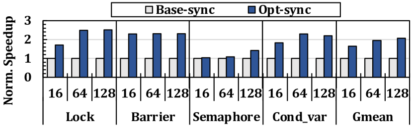
Figure 13 shows the speedup of four microbenchmarks [80, 81], representing four commonly-used synchronization primitives. We show the performance benefit of an M3D configuration where no cache and memory hierarchy latency is paid for synchronization (Opt-sync), over an M3D configuration with the baseline synchronization technique (Base-sync, i.e., coherence-based synchronization). We consider horizontal wire delay (which also exists in the baseline) and only reduce the overhead of accessing the cache and memory hierarchy for synchronization variables. We observe on average 1.88 and up to 2.51 speedup for these microbenchmarks. We conclude that reducing synchronization overhead can provide significant performance benefits to M3D systems and enable more efficient parallelism. Section 6.1 makes a case for using the dense ILV connectivity between different logic layers as a new opportunity to enable efficient inter-thread communication.
5.2.5 Latency of Non-memory Micro-operations
We model an idealized scenario where all µops take one cycle and observe only an on-average 5.4% performance improvement compared to the M3D baseline for compute-bound workloads since most functional units are pipelined. We conclude that lowering the latency of the µops does not lead to significant improvements in our M3D baseline.
6 RevaMp3D: Architecting M3D Based on Our Insights and Observations
This section presents RevaMp3D, the new M3D architecture leveraging our key insights in prior sections666We can combine all the suggested optimizations since they (i) do not cancel each other’s benefits and (ii) can be applied to all workloads with either positive or neutral performance effects. and the new opportunities that the M3D substrate provides. Figure 14 shows an overview of RevaMp3D’s optimizations. We first describe how RevaMp3D leverages the tight connectivity between M3D logic layers to efficiently increase pipeline width, reduce the L1 cache latency, enable fast inter-thread communication (Section 6.1). Second, we explain how RevaMp3D leverages the fast and high-bandwidth main memory of the M3D system to enable the memory-assisted optimizations to address two key challenges of M3D architecture: power consumption and branch misspeculation overhead (Section 6.2). Third, we show the end-to-end performance, energy, power, and area benefits of RevaMp3D (Section 7).

6.1 Leveraging M3D Logic Layers
6.1.1 Cache Hierarchy
The short ILVs enable dividing the SRAM structures between two logic layers to reduce the overall wire lengths in the SRAM structures, leading to reduced access latency [33, 34, 32, 8]. As described in Section 5.1, improving L1 latency improves M3D performance due to M3D’s small AMAT. As shown in the prior work [8], the M3D layout of L1 leads to a 41% latency reduction and a 44% L1 planar footprint reduction. This is because the 3D layout of the L1 cache array leads to overall shorter wire length in the cache array. We adopt a similar technique to improve L1 latency.
As described in Section 5.1, even a large and latency-optimized L2 does not significantly outperform the configuration with no L2. Hence, instead of optimizing the L2 cache, we remove it from the system to save 32% of the logic area. We can spend this freed area on optimizations to alleviate the core bottlenecks.
6.1.2 Pipeline Width
To design wider pipelines, we increase the width and depth of the pipeline SRAM structures (e.g. LS/Q, ROB) to serve a larger number of µops, leading to a 11.6% area overhead per core (7.8% of logic area). By exploiting the multi-layer SRAM structure supported by M3D [33, 8], we increase the size of these structures without increasing their latency and affecting the pipeline frequency.
We need to increase the width of the decode structure and the functional units in the execution stage. Doubling the number of decode structures and functional units (including six integer ALUs, one FPU, and one complex ALU) leads to a 16.5% area overhead per core (11.2% of logic area).777We use McPAT [82] in 22nm technology for area analysis. Even though the absolute area values of the logic components in our CNFET-based M3D baseline does not equal to the values generated by McPAT, we are interested in the area ratio of different logic components. We exploit part of the extra die area freed up due to removing the shared L2 cache to double the number of decode and execution units.
6.1.3 Register File-Level Synchronization
We use the thin inter-layer connections between the logic layers in the M3D system to perform fine-grained inter-thread communication in the register file, instead of the memory hierarchy. The thin ILVs between the logic layers enable increasing the bandwidth of the SRAM structures in the pipeline by adding extra access transistors to each cell. The short ILVs can efficiently connect the extra access transistors in a secondary logic layer to the SRAM cells located on the primary logic layer, without increasing the access latency of the register file. RevaMp3D leverages this to add extra ports to the register file of each processor core and uses the extra ports for fine-grained inter-thread communication in register files.
Since register files have limited sizes, we use them for inter-thread communications that involve small data sizes, such as synchronization primitives. While register file-level communication has been proposed in prior work [83], the adoption of such proposals are challenging in 2D or 3D systems due to the limitations of adding extra ports to the register files. In 2D, this requires connecting the additional ports using long wires that lead to increasing the latency of the register file. In 3D, it is not possible to place the TSVs (which have significantly larger diameter than ILVs) closely together to connect additional access transistor to each cell in a given register file entry. Without adding extra ports to the register file, the inter-thread communication operations need to compete with the main pipeline for the limited register file ports in 2D and 3D systems.
To enable fine-grained locking, where one lock variable is associated with a small amount of application data, each core can write the address of the application data that is being locked by the core to other cores’ register files, instead of using lock variables updated through the cache hierarchy and the coherence protocol.
Figure 15 shows the performance of the register-file synchronization approach (RF-sync) compared to the baseline (Base-sync) and the optimized synchronization (Opt-sync) for the synchronization primitives microbenchmarks. We observe on average 1.78 and up to 2.31 speedup over the baseline for these synchronization microbenchmarks. On two of our workloads, BFS and Radii, in which the ratio of synchronization operations over other computation in the workload is high, we observe 23% and 45% speedup, respectively.

Area and Timing Implications. The register-file synchronization technique can be realized at low area overhead. In fine-grained locking schemes of real workloads, prior works [80, 84] discuss that the number of synchronization variables that are active at any given time during the runtime is small (typically up to 4 variables). Thus, using the register-file mechanism, there is no need for large additional space in the register file. The area overhead of the extra ports that RevaMp3D adds to register-file is very small. Register-file takes 0.2% of the logic area in our baseline. Therefore, the planar area overhead of adding extra ports to 4 entries of the register-file is less than 0.001% of logic area.
Since the extra ports are connected to RF entries from another logic layer using the short vertical ILV connections, they do not change the structure and timing of the register file accesses from the baseline access ports for the baseline core operations.
Security Implications. This technique does not exacerbate the security guarantees of the system compared to baseline due to two reasons. First, we propose this technique for threads that are from the same multi-threaded application (with similar protection domain and from one user). Therefore, threads from different applications, users, or protection domains do not access each other’s data in the register file for synchronization. Second, threads spawned from one application already exchange data through the cache coherence protocol, which has already led to multiple attacks that leverage the coherence traffic to establish side-channels. We conclude that utilizing the register file for synchronization does not open up new attack surfaces and does not exacerbate the existing security issues with data coherence.
6.2 Leveraging M3D Memory Layers
We use the energy-efficient and high-bandwidth M3D main memory to memoize the repetitive fetched, decoded, and re-ordered µops, and turn off the relevant parts of the core pipeline when the same µops execute in a loop. This memoization in main memory addresses two key bottlenecks in the processor cores that we identify in the M3D baseline system. First, it can alleviate the shifted M3D system’s energy bottlenecks that are dominated by the processor core’s energy consumption. As programmers commonly use loops in their codes, we could expect a significant number of instructions to be repeated [43, 85, 44]. Therefore, turning off the fronted and reordering structures can lead to energy saving by eliminating the 48% of the average energy per instruction [44] in the baseline OoO core. Second, this technique alleviates the speculation performance bottleneck that becomes more prominent in M3D. This is because this technique reduces the number of pipeline bubbles in the event of branch misspeculation (as discussed in Section 5.2.2).
In fact, the µop memoization technique has been explored by several prior works [43, 85] that memoize the µops in SRAM-based Execution Caches (EC). The key difference is that our proposal leverages main memory to memoize the µops at lower logic area cost, which is enabled by taking advantage of high-bandwidth and energy-efficient M3D main memory.
Prior work [43] shows that to fully benefit from the µop memoizing technique, we need a large on-chip EC (e.g., up to 100KB) per core, which incurs high area overheads. Our analysis shows that a 100KB EC can occupy 15% of the logic area of the baseline OoO core. Considering a fixed core area budget, this area overhead can come at the cost of key core components and therefore sacrifice performance. Some prior works propose a smaller EC (e.g., 8KB) for area-efficiency but at the cost of memoizability opportunities in applications with a large instruction footprint and large loops [43, 85, 86, 79]. Since M3D main memory provides significant advances in bandwidth and energy consumption over conventional memories in 2D and 3D systems, we implement such memoization techniques inside M3D memory and use a small buffer inside OoO cores to prefetch the memoized µops and provide a one-cycle access latency. This opportunity paves the way for architecting a large and scalable EC at low area cost.
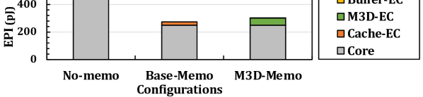

Figure 16 demonstrates the energy saving benefit of the memoization technique by showing the Energy per Instruction (EPI) in three cases: (1) using all core components (No-Memo), (2) memoizing µops in a 100KB-SRAM EC (Baseline-Memo), and (3) memoizing µops in M3D main memory (M3D-Memo). In (2) and (3) the frontend, decode, and reordering structures are power-gated the memoized µops execute. This figure breaks down the EPI to the energy spent on the core, the SRAM-based EC (Cache-EC) used in Baseline-Memo, and the main memory-based EC (M3D-EC) and the small buffer (Buffer-EC) for keeping the prefetched M3D-EC elements used in M3D-Memo. We make two key observations. First, memoizing inside M3D main memory can reduce EPI by 37%. Second, memoizing using 100KB-size SRAM cache (Baseline-Memo) has 11% lower EPI compared to M3D-Memo due to its lower energy per access. However, Baseline-Memo is only the ideal case where we do not penalize the area overhead of other structures. In reality, the 100KB SRAM-based EC can impose large area overhead that can reduce performance by consuming 15% of the processor area budget.
Implementation. We implement M3D-Memo based on prior work [43] that proposes an SRAM-based EC. We place the Memoization Unit (MU) after the issue stage in the processor pipeline. Note that the MU does not add an extra stage to the pipeline since instructions are issued to the execution stage and the MU in parallel. We use the high main memory bandwidth in M3D to memoize both the taken and not-taken paths of hard-to predict branches. The MU has three main components: (i) a small (1.28KB) SRAM buffer to provide one-cycle access latency to the memoized µops, (ii) a simple stride prefetcher that reads µops from the M3D main memory and fills the buffer to hide main memory access latency, and (iii) a memory interface that uses two read/write ports for the taken and not-taken paths and an address bus. We calculate the area of the MU unit using Synopsys Design Compiler and show that the MU unit occupies less than 5% of L1 cache area. We use a preserved address space to store memoized µops. As we are not very limited in space compared to SRAM-based EC, we can capture up to 100% of the memoizable µops.
Performance Implications. M3D-Memo improves the performance of speculation-bound workloads by reducing the pipeline depth and number of pipeline bubbles due to branch misprediction when the processor reads µops from the EC (Section 5.2.2). However, M3D-Memo limits renaming each architectural register to a specific register pool as in prior work [43], which can negatively affect the performance. Similar to prior work [43], we consider an average 6.5% performance loss to model this overhead. However, as we discuss in Section 7.2, the effect of reducing pipeline depth in M3D on average outweighs the renaming overhead. This provides up to 35.5% speedup for speculation-bound workloads, and the modest average speedup of 1.4% across all workloads.
6.3 Impact on Technological Feasibility
As mentioned in Section 2, the feasibility of the baseline M3D system has been validated via fabrication and experimental analysis [5, 3, 57]. In this work, while we focus on architectural exploration, we expect that our architectural changes do not affect routing, power delivery, and manufacturability significantly. This is because we do not add complex or power-hungry structures that would require special techniques for manufacturing on top of the baseline M3D system. Even though production of a system incorporating our design would require engineering effort for new layout design, routing, synthesis, test, and verification, such effort is necessary for any new chip design, and its cost can be mostly amortized over time.
7 End-to-End Evaluation
We first evaluate the performance, energy, and area benefits of RevaMp3D. Second, we show the benefits of RevaMp3D’s optimizations on M3D systems with various main memory configurations that lead to different memory latency values.
7.1 End-to-End Speedup
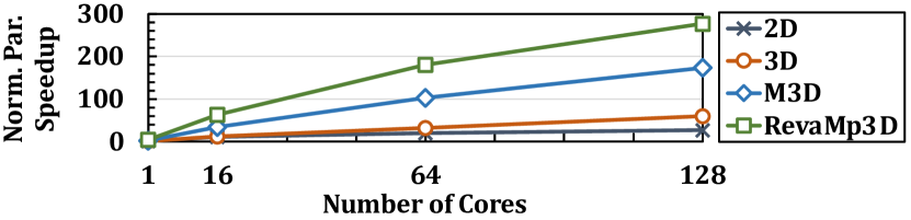
Figure 17 shows the performance improvement of RevaMp3D over the state-of-the-art M3D system, across all workloads in Table 1. Each data point shows the speedup of the optimized M3D with cores over the baseline M3D with cores, where . We make two observations. First, we observe a significant performance improvement, on average 80.6% and 67.6% speedups across all core counts for multi-threaded workloads and multi-programmed workload mixes, respectively. Second, the suggested optimizations improve the performance of all workloads. We conclude that applying our insights is a promising approach towards designing high-performance and area-efficient M3D systems.
Figure 18, we show the performance improvement of RevaMp3D, averaged across all workloads, over the state-of-the-art 2D, 3D, and M3D systems. RevaMp3D provides significant benefits, resulting in 7.14 and 4.96 speedup compared to 2D and 3D, respectively.
7.2 Analysis of Different RevaMp3D’s Configurations
We evaluate the performance and energy benefits of different RevaMp3D’s configurations, each optimized for different goals. Figure 19 shows the normalized (relative to baseline M3D) speedup and energy consumption of each configuration. First, RvM3D-P represents the configuration of RevaMp3D that only applies the performance optimizations in Section 6.1. Second, RvM3D-E represents the configuration of RevaMp3D that only applies the optimizations in Section 6.2, with the main goal of optimizing energy consumption. Third, RvM3D represents a configuration of RevaMp3D that combines both sets of optimizations. Fourth, RvM3D-T represents a low-frequency implementation of RvM3D that is iso-power with the M3D baseline. This configuration is optimized for device temperature since it retains the same power and temperature as the baseline M3D, while providing better performance. We make four major observations.
First, RvM3D-P leads to 2% more energy consumption on average across all workloads. Due to the high energy-efficiency of the M3D main memory, removing the L2 cache does not lead to a significant increase in energy consumption. Increasing the width of the pipeline SRAM structures using the M3D vertical layout [8] does not increase their energy per access since their planar wire length does not increase. Second, RvM3D-E leads to on average 36.3% lower energy consumption across all workloads since for each of our workloads, we observe that at least 99% of their dynamic instructions follow the same schedule. The memoization improves the average performance by an average 1.4% across all workloads and core counts as described in Section 6.2, which leads to an overall 33.9% power consumption reduction. Third, RvM3D leads to an on-average 80.6% performance improvement across all workloads. While the performance optimizations lead to a 83.4% power increase over the baseline M3D, the memoization technique allows this performance improvement at only 27.4% higher power consumption. Fourth, RvM3D-T outperforms the baseline M3D with 4GHz frequency by 60.5%. We conclude that our approach increases the performance per Watt of the system by both improving the performance and lowering the energy consumption.

7.3 Overall Area Reduction
We summarize the area impact for different design decisions in Section 6.1 and Section 6.2 in Table 4. We observe that combining the proposed changes leads to an overall 12.3% area reduction compared to the baseline M3D. This area can be used to further improve M3D performance by increasing the core count or deploying other techniques to alleviate the core bottlenecks.
| Proposed Change | Area Impact (% of logic area) |
|---|---|
| L2 Removal | |
| Wider Pipeline | |
| EC Buffer | |
| Extra register file ports | |
| Total | -12.3% |
7.4 Effect of Main Memory Latency on RevaMp3D’s Design Decisions
While prior work has demonstrated the low memory latency (e.g., 5 ns for reads) of M3D systems using a hardware prototype [5], the latency can vary depending on many design decisions made to meet certain requirements of the target M3D system. For example, a larger memory array increases the wire lengths, which in turn causes larger memory latency. Even though the design decisions for RevaMp3D are based on the state-of-the-art M3D system [5], it is important to analyze them for various latency values. This analysis facilitates picking the right design decisions based on the M3D main memory latency.
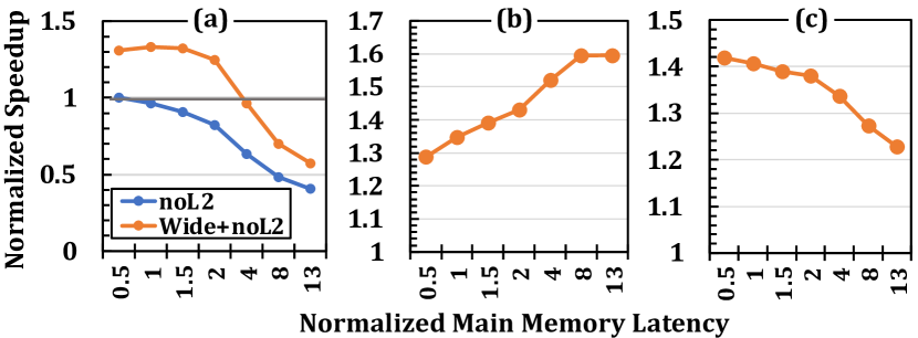
Figure 20 shows how the performance varies depending on the memory latency when we individually apply RevaMp3D’s optimizations to the 64-core baseline M3D system: (a) wider/deeper pipeline (enabled by removing L2 cache), (b) RF-level inter-thread communication, and (c) large execution cache using main memory. For each optimization, we show the example of a workload that has strongest dependence on main memory latency when applying that specific optimization. For (a), we use atax since it actually uses the L2 well with the high cache hit rate of 81%. For (b), we use Radii as our most synchronization-heavy workload. For (c), we use Triangle as the our most speculation-bound workload. For each main memory latency value, performance is normalized to the M3D baseline (with L2 cache and baseline pipeline width) with that memory latency value. We sweep the average memory latency from 0.5 to 13 of the default value (5 ns [5]). The configuration with 0.5 the baseline latency represents an M3D baseline with STT-MRAM. The configuration with 13 larger latency represents an M3D system with average memory latency of the 2D baseline.
We make three key observations. First, until 4 larger than baseline latency values, it is beneficial to use logic area for increasing processing capability (e.g., wider pipeline) instead of larger caches. This is because the large main memory bandwidth enables serving a larger number of in-flight requests in M3D. However, for larger latency values, having a larger cache hierarchy becomes critical. Second, as the main memory latency increases, the performance benefit of the register file-level synchronization technique increases. Third, the performance benefit of the memoization technique decreases for larger latency values because the relative impact of speculation bottleneck decreases as the main memory latency increases.888In this sensitivity analysis, we only focus on the performance implication of this technique and do not analyze the energy implications because a latency value can be achieved via different design decisions, which can potentially impact energy in different ways. Low-energy and high-bandwidth main memory is the key enabler of this technique since the memoized µops can be sequentially prefetched from main memory with high bandwidth. However, by increasing the main memory latency, the size of the buffer in the Memoization Unit needs to increase proportionally.
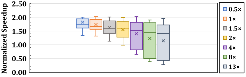
Figure 21 shows the distribution of the end-to-end performance benefit of RevaMp3D’s optimization (based on the trade-offs originally made for the M3D system with the baseline latency) for M3D systems with different latency values, across all the workloads and with a 64-core configuration. We observe that RevaMp3D’s design choices provide speedup for all workloads in the M3D system with up to 2 larger latency, while some workloads show slowdown as the memory latency increases.
While all RevaMp3D design choices do not lead to performance benefits for M3D systems with high main memory latency, the high-bandwidth connectivity between M3D device layers can still provide several key benefits for such M3D systems. First, as we discussed, several optimizations in RevaMp3D that are enabled by the high-bandwidth integration of logic and memory layers can provide performance/energy benefits irrespective of memory latency. Second, M3D can facilitate implementing latency hiding optimizations. For example, M3D can enable high-bandwidth SRAM structures in the pipeline, which can facilitate accessing multiple thread contexts in a core (e.g., with simultaneous multi-threading).
8 Discussion
8.1 Scaling Data Size Beyond Main Memory Capacity
While a system with a single M3D chip can potentially provide hundreds of gigabytes of main memory [5, 3], for even larger requirements, a system can employ multiple M3D chips, where the off-chip accesses cost more overhead than the on-chip accesses. To address this overhead, techniques that alleviate the remote access overhead using scheduling, data placement, replication, or migration can be applied in M3D, even with lower restrictions [48, 87, 88]. This is because RRAM used in our baseline M3D system enables denser main memory compared to conventional DRAM-based 3D or 2D systems and can reduce the number of remote accesses.
8.2 Other Impacts of M3D in System Stack
We discuss optimizations that M3D can further enable in processing using memory and in the software domain.
Fine-Grained Acceleration with Processing Using Memory. M3D enables new opportunities in processing using memory (PuM). The tight integration between the memory and logic layers enables tighter connection between the PuM engine (in memory layers) and the general-purpose cores (in the logic layers). This close coupling introduces opportunities for fine-grained acceleration of applications since the data between the cores and accelerators can move very fast.
HW/SW Co-design. Memory bottleneck has affected both hardware and software in today’s systems. This work explores the implications of the shifted system bottlenecks on hardware design of cores and caches. We believe that it is essential to also revisit the software stack to better leverage the underlying M3D hardware. In the operating systems, memory management and process management units can be revisited to be aware of M3D’s trade-offs. At the application-level, it is critical to revisit the trade-offs in optimizations targeted towards addressing memory bottlenecks versus other bottlenecks demonstrated in this work. We hope our analysis of new bottlenecks and opportunities of M3D guide future software development for this emerging technology.
Applicability to Domain-Specific Systems.
While our work focuses on general-purpose systems, our observations and design trade-offs can also be considered in designing domain-specific systems. For example, we expect to observe performance and energy bottleneck shifts as we observed in our study. Based on the structure of the accelerator, the alleviated memory bottleneck can enable reducing the size of on-chip storage and buffers, increasing the width or number of processing elements, and provide memoization opportunities to leverage M3D memory to reduce the energy consumption. The tight connection between the layers can facilitate communication between different accelerators or between the accelerator and the general purpose processing units in different logic layers in M3D. A detailed analysis of domain-specific M3D requires its own separate study based on the accelerator domain and is outside the scope of this work.
9 Related Work
To our knowledge, this is the first work to comprehensively explore an efficient M3D architecture for general-purpose computing, based on rigorous bottleneck analysis using a wide range of workloads. We briefly discuss previous works in designing M3D systems.
Device and Circuit-Level Integration. Many works [11, 12, 13, 14, 15, 16, 17, 18, 19] focus on the design of efficient M3D devices with respect to performance, power, energy, temperature, and reliability. Other studies show the benefits of M3D device technology in comparison to TSV-based technologies[20, 21]. Several works [22, 23, 24] study the efficient physical integration and layout designs for monolithic logic and memory layers. Several works explore and leverage heterogeneous device layers in M3D [25, 26, 27, 28].
Designing M3D-Based Processors. Recent works propose a 3D partitioning technique for logic-only M3D processors[29, 30, 8] to improve the latency of different pipeline components by decreasing their wire lengths. Other recent works show how to leverage M3D to design efficient SRAM memories [32, 33, 34, 35] or networks-on-chip in M3D [31, 29]. Some works [31, 23] discuss the memory system challenges in M3D, such as optimizing the memory array structures, and the need for developing techniques to increase memory parallelism (e.g., SIMD units, non-blocking loads).
While prior works propose various advances in M3D, we analyze the implications of this technology on both (i) the real-world application bottlenecks and (ii) architectural designs which have been conventionally specialized to tackle the memory bottleneck. For example, while prior works propose optimizations to caches in M3D [8, 5], we show that such optimizations are not essential beyond L1.
Accelerating Emerging Applications Using M3D. Multiple works [89, 36, 37, 38, 39, 40, 30] design domain-specific accelerators in M3D [42, 41]. Some works [90] suggest reconfigurable fabrics, such as FPGAs for hardware acceleration in M3D.
3D-Integrated Caches. Some prior works propose 3D-integrated caches to achieve low access latency and high bandwidth, such as AMD’s 3D SRAM V-Cache [91] and SILO [92]. However, due to their inherently limited capacity (currently 64 MB for V-Cache and 512 MB for SILO), these solutions cannot fully address main memory bottleneck. As shown in Section 5.1.2, workloads with large working sets and poor cache utilization do not benefit from large caches.
10 Conclusion
To our knowledge, this is the first work to redesign core and cache hierarchy for a general-purpose M3D system based on rigorous bottleneck analysis of a wide range of real-world workloads, and the new trade-offs imposed by M3D technology. We show that the performance and energy bottlenecks shift in M3D systems from main memory to processor core and memory hierarchy. We conduct a design space exploration of the processor core and cache hierarchy in M3D. We design RevaMp3D, an M3D system based on our key insights and leverging the key opportunities of the M3D technology: (i) tightly-integrated logic layers and (ii) fast and energy-efficient main memory. RevaMp3D provides significant performance improvement and energy reduction compared to the state-of-the-art M3D system at lower area cost.
References
- [1] Max M Shulaker, Gage Hills, Nishant Patil, Hai Wei, Hong-Yu Chen, H-S Philip Wong, and Subhasish Mitra. Carbon nanotube computer. Nature, 501(7468):526–530, 2013.
- [2] Max M Shulaker, Tony F Wu, Asish Pal, Liang Zhao, Yoshio Nishi, Krishna Saraswat, H-S Philip Wong, and Subhasish Mitra. Monolithic 3D Integration of Logic and Memory: Carbon Nanotube FETs, Resistive RAM, and Silicon FETs. In IEDM, 2014.
- [3] Max M Shulaker, Gage Hills, Rebecca S Park, Roger T Howe, Krishna Saraswat, H-S Philip Wong, and Subhasish Mitra. Three-dimensional integration of nanotechnologies for computing and data storage on a single chip. Nature, 547(7661):74–78, 2017.
- [4] Mohamed M Sabry Aly, Mingyu Gao, Gage Hills, Chi-Shuen Lee, Greg Pitner, Max M Shulaker, Tony F Wu, Mehdi Asheghi, Jeff Bokor, Franz Franchetti, Kenneth E Goodson, Christos Kozyrakis, Igor Markov, Kunle Olukotun, Larry Pileggi, Eric Pop, Jan Rabaey, Christopher Re, H.-S. Philip Wong, and Subhasish Mitra. Energy-efficient abundant-data computing: The n3xt 1,000 x. Computer, 48(12):24–33, 2015.
- [5] Mohamed M Sabry Aly, Tony F Wu, Andrew Bartolo, Yash H Malviya, William Hwang, Gage Hills, Igor Markov, Mary Wootters, Max M Shulaker, H-S Philip Wong, and Subhasish Mitra. The N3XT Approach to Energy-Efficient Abundant-Data Computing. IEEE ’18.
- [6] NVidia. NVIDIA A100 Tensor Core GPU Architecture, 2020. https://www.nvidia.com/en-us/data-center/a100/.
- [7] SK Hynix. Fastest DRAM with enhanced heat dissipation, 2021. https://product.skhynix.com/products/dram/hbm/hbm2e.go.
- [8] Bhargava Gopireddy and Josep Torrellas. Designing Vertical Processors in Monolithic 3D. In ISCA, 2019.
- [9] Akifumi Kawahara, Ryotaro Azuma, Yuuichirou Ikeda, Ken Kawai, Yoshikazu Katoh, Yukio Hayakawa, Kiyotaka Tsuji, Shinichi Yoneda, Atsushi Himeno, Kazuhiko Shimakawa, Takeshi Takagi, Takumi Mikawa, and Aono Kunitoshi. An 8 mb multi-layered cross-point reram macro with 443 mb/s write throughput. IEEE Journal of Solid-State Circuits, 48(1):178–185, 2012.
- [10] Chung-Cheng Chou, Zheng-Jun Lin, Pei-Ling Tseng, Chih-Feng Li, Chih-Yang Chang, Wei-Chi Chen, Yu-Der Chih, and Tsung-Yung Jonathan Chang. An n40 256k 44 embedded rram macro with sl-precharge sa and low-voltage current limiter to improve read and write performance. In 2018 IEEE International Solid-State Circuits Conference-(ISSCC), pages 478–480. IEEE, 2018.
- [11] Bon Woong Ku, Peter Debacker, Dragomir Milojevic, Praveen Raghavan, Diederik Verkest, Aaron Thean, and Sung Kyu Lim. Physical design solutions to tackle feol/beol degradation in gate-level monolithic 3d ics. In Proceedings of the 2016 International Symposium on Low Power Electronics and Design, pages 76–81, 2016.
- [12] Chang Liu and Sung Kyu Lim. A design tradeoff study with monolithic 3d integration. In Thirteenth International Symposium on Quality Electronic Design (ISQED), pages 529–536. IEEE, 2012.
- [13] Shreepad Panth, Sandeep Samal, Yun Seop Yu, and Sung Kyu Lim. Design challenges and solutions for ultra-high-density monolithic 3d ics. In 2014 SOI-3D-Subthreshold Microelectronics Technology Unified Conference (S3S), pages 1–2. IEEE, 2014.
- [14] Kyungwook Chang, Abhishek Koneru, Krishnendu Chakrabarty, and Sung Kyu Lim. Design automation and testing of monolithic 3d ics: Opportunities, challenges, and solutions. In 2017 IEEE/ACM International Conference on Computer-Aided Design (ICCAD), pages 805–810. IEEE, 2017.
- [15] Sandeep Kumar Samal, Shreepad Panth, Kambiz Samadi, Mehdi Saedi, Yang Du, and Sung Kyu Lim. Fast and Accurate Thermal Modeling and Optimization for Monolithic 3D ICs. In DAC ’14.
- [16] Prachi Shukla, Ayse K Coskun, Vasilis F Pavlidis, and Emre Salman. An overview of thermal challenges and opportunities for monolithic 3d ics. In Proceedings of the 2019 on Great Lakes Symposium on VLSI, pages 439–444, 2019.
- [17] Dongjin Lee, Sourav Das, Janardhan Rao Doppa, Partha Pratim Pande, and Krishnendu Chakrabarty. Performance and thermal tradeoffs for energy-efficient monolithic 3d network-on-chip. ACM Transactions on Design Automation of Electronic Systems (TODAES), 23(5):1–25, 2018.
- [18] Sandeep Kumar Samal, Kambiz Samadi, Pratyush Kamal, Yang Du, and Sung Kyu Lim. Full chip impact study of power delivery network designs in monolithic 3d ics. In 2014 IEEE/ACM International Conference on Computer-Aided Design (ICCAD), pages 565–572. IEEE, 2014.
- [19] Melanie Brocard, Benoit Mathieu, Jean-Philippe Colonna, Cristiano Santos, Claire Fenouillet-Beranger, Vincent Lu Cao-Minh, Gerald Cibrario, Laurent Brunet, Perrine Batude, François Andrieu, Sebastien Thuries, and Olivier Billoint. Transistor temperature deviation analysis in monolithic 3d standard cells. In 2017 IEEE Computer Society Annual Symposium on VLSI (ISVLSI), pages 539–544. IEEE, 2017.
- [20] Sandeep Kumar Samal, Deepak Nayak, Motoi Ichihashi, Srinivasa Banna, and Sung Kyu Lim. Monolithic 3d ic vs. tsv-based 3d ic in 14nm finfet technology. In 2016 IEEE SOI-3D-Subthreshold Microelectronics Technology Unified Conference (S3S), pages 1–2. IEEE, 2016.
- [21] Deepak Kumar Nayak, Srinivasa Banna, Sandeep Kumar Samal, and Sung Kyu Lim. Power, performance, and cost comparisons of monolithic 3d ics and tsv-based 3d ics. In 2015 IEEE SOI-3D-Subthreshold Microelectronics Technology Unified Conference (S3S), pages 1–2. IEEE, 2015.
- [22] Meenatchi Jagasivamani, Candace Walden, Devesh Singh, Luyi Kang, Shang Li, Mehdi Asnaashari, Sylvain Dubois, Bruce Jacob, and Donald Yeung. Analyzing the monolithic integration of a reram-based main memory into a cpu’s die. IEEE Micro, 39(6):64–72, 2019.
- [23] Candace Walden, Devesh Singh, Meenatchi Jagasivamani, Shang Li, Luyi Kang, Mehdi Asnaashari, Sylvain Dubois, Bruce Jacob, and Donald Yeung. Monolithically integrating non-volatile main memory over the last-level cache. ACM Transactions on Architecture and Code Optimization (TACO), 18(4):1–26, 2021.
- [24] Meenatchi Jagasivamani, Candace Walden, Devesh Singh, Luyi Kang, Shang Li, Mehdi Asnaashari, Sylvain Dubois, Donald Yeung, and Bruce Jacob. Design for reram-based main-memory architectures. In Proceedings of the International Symposium on Memory Systems, pages 342–350, 2019.
- [25] Farzaneh Zokaee, Mingzhe Zhang, Xiaochun Ye, Dongrui Fan, and Lei Jiang. Magma: A monolithic 3d vertical heterogeneous reram-based main memory architecture. In 2019 56th ACM/IEEE Design Automation Conference (DAC), pages 1–6. IEEE, 2019.
- [26] Gauthaman Murali, Xiaoyu Sun, Shimeng Yu, and Sung Kyu Lim. Heterogeneous mixed-signal monolithic 3-d in-memory computing using resistive ram. IEEE Transactions on Very Large Scale Integration (VLSI) Systems, 29(2):386–396, 2020.
- [27] Anwesha Chatterjee, Shouvik Musavvir, Ryan Gary Kim, Janardhan Rao Doppa, and Partha Pratim Pande. Power management of monolithic 3d manycore chips with inter-tier process variations. ACM Journal on Emerging Technologies in Computing Systems (JETC), 17(2):1–19, 2021.
- [28] Gauthaman Murali and Sung Kyu Lim. Heterogeneous 3d ics: Current status and future directions for physical design technologies. In 2021 Design, Automation & Test in Europe Conference & Exhibition (DATE), pages 146–151. IEEE, 2021.
- [29] Dylan Stow, Itir Akgun, Wenqin Huangfu, Yuan Xie, Xueqi Li, and Gabriel H Loh. Efficient System Architecture in the Era of Monolithic 3D: Dynamic Inter-tier Interconnect and Processing-in-Memory. In DAC ’19, 2019.
- [30] Biresh Kumar Joardar, Aqeeb Iqbal Arka, Janardhan Rao Doppa, and Partha Pratim Pande. 3d++: Unlocking the next generation of high-performance and energy-efficient architectures using m3d integration. In 2021 Design, Automation & Test in Europe Conference & Exhibition (DATE), pages 158–163. IEEE, 2021.
- [31] Meenatchi Jagasivamani, Candace Walden, Devesh Singh, Luyi Kang, Shang Li, Mehdi Asnaashari, Sylvain Dubois, Bruce Jacob, and Donald Yeung. Memory-systems challenges in realizing monolithic computers. In Proceedings of the International Symposium on Memory Systems, pages 98–104, 2018.
- [32] Srivatsa Srinivasa, Akshay Krishna Ramanathan, Xueqing Li, Wei-Hao Chen, Fu-Kuo Hsueh, Chih-Chao Yang, Chang-Hong Shen, Jia-Min Shieh, Sumeet Gupta, Meng-Fan Marvin Chang, Swaroop Ghosh, Jack Sampson, and Vijaykrishnan Narayanan. A monolithic-3d sram design with enhanced robustness and in-memory computation support. In Proceedings of the International Symposium on Low Power Electronics and Design, pages 1–6, 2018.
- [33] Srivatsa Srinivasa, Wei-Hao Chen, Yung-Ning Tu, Meng-Fan Chang, Jack Sampson, and Vijaykrishnan Narayanan. Monolithic-3d integration augmented design techniques for computing in srams. In 2019 IEEE International Symposium on Circuits and Systems (ISCAS), pages 1–5. IEEE, 2019.
- [34] Srivatsa Srinivasa, Yung-Ning Tu, Xin Si, Cheng-Xin Xue, Chun-Ying Lee, Fu-Kuo Hsueh, Chane-Hone Shen, Jia-Min Shieh, Wen-Kuan Yeh, Akshay Krishna Ramanathan, Mon-Shu Ho, Jack Sampson, Meng-Fan Chang, and Vijaykrishnan Narayanan. Monolithic 3d+-ic based reconfigurable compute-in-memory sram macro. In 2019 Symposium on VLSI Technology, pages T32–T33. IEEE, 2019.
- [35] Joonho Kong, Young-Ho Gong, and Sung Woo Chung. Architecting large-scale sram arrays with monolithic 3d integration. In 2017 IEEE/ACM International Symposium on Low Power Electronics and Design (ISLPED), pages 1–6. IEEE, 2017.
- [36] Abdallah M. Felfl, Kamalika Datta, Arko Dutt, Hasita Veluri, Ahmed Zaky, Aaron Voon-Yew Thean, and Mohamed M. Sabry Aly. Quantifying the benefits of monolithic 3d computing systems enabled by tft and rram. In Proceedings of the 23rd Conference on Design, Automation and Test in Europe, DATE ’20, page 43–48, 2020.
- [37] Ye Yu and Niraj K Jha. Spring: A sparsity-aware reduced-precision monolithic 3d cnn accelerator architecture for training and inference. IEEE Transactions on Emerging Topics in Computing, 2020.
- [38] Sho Ko, Yun Joon Soh, and Jishen Zhao. Efficient implementation of multi-channel convolution in monolithic 3d reram crossbar. arXiv preprint arXiv:2004.00243, 2020.
- [39] Yu Huang, Long Zheng, Xiaofei Liao, Hai Jin, Pengcheng Yao, and Chuangyi Gui. Ragra: Leveraging monolithic 3d reram for massively-parallel graph processing. In 2019 Design, Automation & Test in Europe Conference & Exhibition (DATE), pages 1273–1276. IEEE, 2019.
- [40] Muhammad Abdullah Hanif, Aditya Manglik, and Muhammad Shafique. Resistive crossbar-aware neural network design and optimization. IEEE Access, 2020.
- [41] Tony F Wu, Haitong Li, Ping-Chen Huang, Abbas Rahimi, Jan M Rabaey, H-S Philip Wong, Max M Shulaker, and Subhasish Mitra. Brain-inspired computing exploiting carbon nanotube fets and resistive ram: Hyperdimensional computing case study. In 2018 IEEE International Solid-State Circuits Conference-(ISSCC), pages 492–494. IEEE, 2018.
- [42] Tony F Wu, Haitong Li, Ping-Chen Huang, Abbas Rahimi, Gage Hills, Bryce Hodson, William Hwang, Jan M Rabaey, H-S Philip Wong, Max M Shulaker, and Subhasish Mitra. Hyperdimensional computing exploiting carbon nanotube fets, resistive ram, and their monolithic 3d integration. IEEE Journal of Solid-State Circuits, 53(11):3183–3196, 2018.
- [43] Emil Talpes and Diana Marculescu. Execution cache-based microarchitecture for power-efficient superscalar processors. IEEE Transactions on Very Large Scale Integration (VLSI) Systems, 13(1):14–26, 2005.
- [44] Baruch Solomon, Avi Mendelson, Ronny Ronen, Doron Orenstien, and Yoav Almog. Micro-operation cache: A power aware frontend for variable instruction length isa. IEEE Transactions on Very Large Scale Integration (VLSI) Systems, 11(5):801–811, 2003.
- [45] Daniel Sanchez and Christos Kozyrakis. ZSim: Fast and Accurate Microarchitectural Simulation of Thousand-Core Systems. In ISCA ’13.
- [46] Makoto Motoyoshi. Through-Silicon Via (TSV). Proceedings of the IEEE, 2009.
- [47] Onur Mutlu, Saugata Ghose, Juan Gómez-Luna, and Rachata Ausavarungnirun. A Modern Primer on Processing in Memory. Emerging Computing: From Devices to Systems - Looking Beyond Moore and Von Neumann, 2021.
- [48] J. Ahn, S. Hong, S. Yoo, O. Mutlu, and K. Choi. A Scalable Processing-in-memory Accelerator for Parallel Graph Processing. In ISCA ’15.
- [49] Junwhan Ahn, Sungjoo Yoo, Onur Mutlu, and Kiyoung Choi. PIM-enabled Instructions: A Low-overhead, Locality-aware Processing-in-memory Architecture. In ISCA ’15.
- [50] Amirali Boroumand, Saugata Ghose, Youngsok Kim, Rachata Ausavarungnirun, Eric Shiu, Rahul Thakur, Daehyun Kim, Aki Kuusela, Allan Knies, Parthasarathy Ranganathan, and Onur Mutlu. Google Workloads for Consumer Devices: Mitigating Data Movement Bottlenecks. In ASPLOS ’18.
- [51] Amirali Boroumand, Saugata Ghose, Minesh Patel, Hasan Hassan, Brandon Lucia, Rachata Ausavarungnirun, Kevin Hsieh, Nastaran Hajinazar, Krishna T Malladi, Hongzhong Zheng, and Onur Mutlu. CoNDA: Efficient Cache Coherence Support for Near-Data Accelerators. In ISCA ’19.
- [52] Kevin Hsieh, Samira Khan, Nandita Vijaykumar, Kevin K Chang, Amirali Boroumand, Saugata Ghose, and Onur Mutlu. Accelerating Pointer chasing in 3D-stacked Memory: Challenges, Mechanisms, Evaluation. In ICCD ’16.
- [53] Ravi Nair, Samuel F Antao, Carlo Bertolli, Pradip Bose, Jose R Brunheroto, Tong Chen, C-Y Cher, Carlos HA Costa, Jun Doi, and Constantinos Evangelinos. Active Memory Cube: A Processing-in-memory Architecture for Exascale Systems. IBM Journal of Research and Development ’15.
- [54] Lifeng Nai, Ramyad Hadidi, Jaewoong Sim, Hyojong Kim, Pranith Kumar, and Hyesoon Kim. GraphPIM : Enabling Instruction-Level PIM Offloading in Graph Computing Frameworks. In HPCA ’17.
- [55] Seongguk Kim, Subin Kim, Kyungjun Cho, Taein Shin, Hyunwook Park, Daehwan Lho, Shinyoung Park, Kyungjune Son, Gapyeol Park, Seungtaek Jeong, Youngwoo Kim, and Joungho Kim. Signal integrity and computing performance analysis of a processing-in-memory of high bandwidth memory (pim-hbm) scheme. IEEE Transactions on Components, Packaging and Manufacturing Technology, 2021.
- [56] Jack Choquette, Wishwesh Gandhi, Olivier Giroux, Nick Stam, and Ronny Krashinsky. NVIDIA A100 Tensor Core GPU: Performance and Innovation. IEEE Micro, 2021.
- [57] Mindy D Bishop, Gage Hills, Tathagata Srimani, Christian Lau, Denis Murphy, Samuel Fuller, Jefford Humes, Anthony Ratkovich, Mark Nelson, and Max M Shulaker. Fabrication of carbon nanotube field-effect transistors in commercial silicon manufacturing facilities. Nature Electronics, 3(8):492–501, 2020.
- [58] Joseph Redmon. Darknet: Open Source Neural Networks in C. http://pjreddie.com/darknet, 2013.
- [59] Julian Shun and Guy E Blelloch. Ligra: A Lightweight Graph Processing Framework for Shared Memory. In PPoPP, 2013.
- [60] John D. McCalpin. STREAM: Sustainable Memory Bandwidth in High Performance Computers. Technical report, University of Virginia, 1991-2007. A continually updated technical report. http://www.cs.virginia.edu/stream/.
- [61] Shuai Che, Michael Boyer, Jiayuan Meng, David Tarjan, Jeremy W Sheaffer, Sang-Ha Lee, and Kevin Skadron. Rodinia: A Benchmark Suite for Heterogeneous Computing. In IISWC ’09.
- [62] Steven Cameron Woo, Moriyoshi Ohara, Evan Torrie, Jaswinder Pal Singh, and Anoop Gupta. The SPLASH-2 Programs: Characterization and Methodological Considerations. ISCA ’95.
- [63] Louis-Noël Pouchet. Polybench: The Polyhedral Benchmark Suite. URL: http://www. cs. ucla. edu/pouchet/software/polybench, 2012.
- [64] Christian Bienia, Sanjeev Kumar, Jaswinder Pal Singh, and Kai Li. The PARSEC Benchmark Suite: Characterization and Architectural Implications. In PACT ’08.
- [65] Ahmad Yasin. A Top-Down Method for Performance Analysis and Counters Architecture. In ISPASS ’14.
- [66] Svilen Kanev, Juan Pablo Darago, Kim Hazelwood, Parthasarathy Ranganathan, Tipp Moseley, Gu-Yeon Wei, and David Brooks. Profiling a Warehouse-Scale Computer. In ISCA, 2015.
- [67] Utku Sirin, Ahmad Yasin, and Anastasia Ailamaki. A Methodology for OLTP Micro-Architectural Analysis. In DAMON, 2017.
- [68] R. Appuswamy, J. Fellay, and N. Chaturvedi. Sequence Alignment Through the Looking Glass. In IPDPSW, 2018.
- [69] Intel. Intel VTune Amplifier 2019 User Guide, 2018. https://software.intel.com/en-us/vtune-amplifier-help.
- [70] Bernard Goossens, Philippe Langlois, David Parello, and Eric Petit. PerPI: A Tool to Measure Instruction Level Parallelism. In International Workshop on Applied Parallel Computing, 2010.
- [71] Geraldo F Oliveira, Juan Gómez-Luna, Lois Orosa, Saugata Ghose, Nandita Vijaykumar, Ivan Fernandez, Mohammad Sadrosadati, and Onur Mutlu. Damov: A new methodology and benchmark suite for evaluating data movement bottlenecks. arXiv preprint arXiv:2105.03725, 2021.
- [72] S. Ghose, T. Li, N. Hajinazar, D. Senol Cali, and O. Mutlu. Demystifying Complex Workload–DRAM Interactions: An Experimental Study. In SIGMETRICS, 2020.
- [73] Vikram Sharma Mailthody, Zaid Qureshi, Weixin Liang, Ziyan Feng, Simon Garcia De Gonzalo, Youjie Li, Hubertus Franke, Jinjun Xiong, Jian Huang, and Wen-mei Hwu. Deepstore: In-storage acceleration for intelligent queries. In Proceedings of the 52nd Annual IEEE/ACM International Symposium on Microarchitecture, pages 224–238, 2019.
- [74] Po-An Tsai, Changping Chen, and Daniel Sanchez. Adaptive Scheduling for Systems with Asymmetric Memory Hierarchies. In MICRO ’18.
- [75] Tse-Yu Yeh and Yale N Patt. Two-level adaptive training branch prediction. In Proceedings of the 24th annual international symposium on Microarchitecture, pages 51–61, 1991.
- [76] André Seznec. Tage-sc-l branch predictors again. In 5th JILP Workshop on Computer Architecture Competitions (JWAC-5): Championship Branch Prediction (CBP-5), 2016.
- [77] Aydin O Balkan, Gang Qu, and Uzi Vishkin. Mesh-of-trees and alternative interconnection networks for single-chip parallelism. IEEE Transactions on Very Large Scale Integration (VLSI) Systems, 17(10):1419–1432, 2009.
- [78] Jacob Benesty, Jingdong Chen, Yiteng Huang, and Israel Cohen. Pearson correlation coefficient. In Noise reduction in speech processing, pages 1–4. Springer, 2009.
- [79] Shruti Padmanabha, Andrew Lukefahr, Reetuparna Das, and Scott Mahlke. Mirage cores: The illusion of many out-of-order cores using in-order hardware. In Proceedings of the 50th Annual IEEE/ACM International Symposium on Microarchitecture, pages 745–758, 2017.
- [80] Tudor David, Rachid Guerraoui, and Vasileios Trigonakis. Everything you always wanted to know about synchronization but were afraid to ask. In Proceedings of the Twenty-Fourth ACM Symposium on Operating Systems Principles, pages 33–48, 2013.
- [81] Tudor David. Libslock. URL: https://github.com/tudordavid/libslock.
- [82] Sheng Li, Jung Ho Ahn, Richard D Strong, Jay B Brockman, Dean M Tullsen, and Norman P Jouppi. Mcpat: An integrated power, area, and timing modeling framework for multicore and manycore architectures. In Proceedings of the 42nd Annual IEEE/ACM International Symposium on Microarchitecture, pages 469–480, 2009.
- [83] Stephen W Keckler, William J Dally, Daniel Maskit, Nicholas P Carter, Andrew Chang, and Whay S Lee. Exploiting fine-grain thread level parallelism on the mit multi-alu processor. ACM SIGARCH Computer Architecture News, 26(3):306–317, 1998.
- [84] Christina Giannoula, Nandita Vijaykumar, Nikela Papadopoulou, Vasileios Karakostas, Ivan Fernandez, Juan Gómez-Luna, Lois Orosa, Nectarios Koziris, Georgios Goumas, and Onur Mutlu. Syncron: Efficient synchronization support for near-data-processing architectures. In 2021 IEEE International Symposium on High-Performance Computer Architecture (HPCA), pages 263–276. IEEE, 2021.
- [85] Emil Talpes and Diana Marculescu. Power reduction through work reuse. In Proceedings of the 2001 international symposium on Low power electronics and design, pages 340–345, 2001.
- [86] Shruti Padmanabha, Andrew Lukefahr, Reetuparna Das, and Scott Mahlke. Dynamos: Dynamic schedule migration for heterogeneous cores. In Proceedings of the 48th International Symposium on Microarchitecture, pages 322–333, 2015.
- [87] Xulong Tang, Orhan Kislal, Mahmut Kandemir, and Mustafa Karakoy. Data movement aware computation partitioning. In MICRO ’17.
- [88] Shuang Chen, Yi Jiang, Christina Delimitrou, and José F Martínez. Pimcloud: Qos-aware resource management of latency-critical applications in clouds with processing-in-memory. In 2022 IEEE International Symposium on High-Performance Computer Architecture (HPCA), pages 1086–1099. IEEE, 2022.
- [89] Fan Chen, Linghao Song, Hai Li, and Yiran Chen. Marvel: A vertical resistive accelerator for low-power deep learning inference in monolithic 3d. In 2021 Design, Automation & Test in Europe Conference & Exhibition (DATE), pages 1240–1245. IEEE, 2021.
- [90] Ye Yu and Niraj K Jha. A monolithic 3d hybrid architecture for energy-efficient computation. IEEE Transactions on Multi-Scale Computing Systems, 4(4):533–547, 2018.
- [91] AMD. AMD Accelerating – The High Performance Computing Ecosystem, 2021. https://www.amd.com/en/events/computex.
- [92] Amna Shahab, Mingcan Zhu, Artemiy Margaritov, and Boris Grot. Farewell My Shared LLC! A Case for Private Die-Stacked DRAM Caches for Servers. In MICRO, 2018.