Building blocks of non-Euclidean ribbons: Size-controlled self-assembly via discrete frustrated particles
Abstract
Geometric frustration offers a pathway to soft matter self-assembly with controllable finite sizes. While the understanding of frustration in soft matter assembly derives almost exclusively from continuum elastic descriptions, a current challenge is to understand the connection between microscopic physical properties of misfitting “building blocks” and emergent assembly behavior at mesoscale. We present and analyze a particle-based description of what is arguably the best studied example for frustrated soft matter assembly, negative-curvature ribbon assembly, observed in both assemblies of chiral surfactants and shape-frustrated nanoparticles. Based on our particle model, known as saddle wedge monomers, we numerically test the connection between microscopic shape and interactions of the misfitting subunits and the emergent behavior at the supra-particle scale, specifically focussing on the propagation and relaxation of inter-particle strains, the emergent role of extrinsic shape on frustrated ribbons and the equilibrium regime of finite width selection. Beyond the intuitive role of shape misfit, we show that self-limitation is critically dependent on the finite range of cohesive interactions, with larger size finite assemblies requiring increasing short-range interparticle forces. Additionally, we demonstrate that non-linearities arising from discrete particle interactions alter self-limiting behavior due to both strain-softening in shape-flattened assembly and partial yielding of highly strained bonds, which in turn may give rise to states of hierarchical, multidomain assembly. Tracing the regimes of frustration-limited assembly to the specific microscopic features of misfitting particle shapes and interactions provides necessary guidance for translating the theory of size-programmable assembly into design of intentionally-frustrated colloidal particles.
I Introduction
Geometric frustration (GF) occurs when the locally preferred ordering is incompatible with geometric constraints of extending that order throughout the assembly. [1, 2] Canonically, GF is associate in bulk systems, where it requires the formation of extensive arrays of topological defects, as in polytetrahedral sphere packings [3] or liquid crystal blue phases .[4] When a self-assembling system has GF, the presence of free boundaries on potentially forming finite-sized structures leads to distinct consequences and a range of exotic, scale-dependent thermodynamic behavior. [5] Notably, finite and sufficiently soft assemblies need not form defects as response to GF, which may instead manifest in a superextensive accumulation of intra-assembly stress that, in competition with the cohesive drive for assembly growth, may shape the assembly’s equilbrium boundary and interior at length scales much larger than the subunit (e.g. macromolular or colloidal) dimensions. [5, 6] Arguably, the most notable emergent behavior is the ability of the GF to determine the mesoscopic finite equilibrium size of assemblies. [7] This basic paradigm has been explored in the context of a range of soft matter systems, from spherical assemblies of colloids [8, 9] and protein shells, [10] to twisted bundles of filamentous proteins or chiral fibers [11, 12, 13] and chiral ribbons. [14, 15, 16, 17, 18, 19] The specific dependence on long-range gradients in intra-assembly stress and the resulting ability of thermodynamics to sense the mesoscopic size of assemblies distinguishes geometrically frustrated assembly (GFA) from other more familiar examples of size-selective assemblies, like amphiphillic micelles or self-closing, curvature limited shells and tubules.
Models for size control in GFAs are generically predicated on continuum elastic descriptions of the super-extensive growth in assembly energy. [7] These models argue that elastic energy accumulates with size up to an upper size limit, beyond which the assembly distorts away from the locally-preferred packing (at finite energy cost) to maintain extensive energetic growth with size. [6] At these large sizes, frustration is not able to restrain the cohesive drive to larger size, and equilibrium assembly proceeds to unlimited size, known as frustration escape. There are multiple possible structural modes of assembly: elastic “shape flattening” of the preferred frustrated packing into an unfrustrated one; [12, 20, 21] “filamentation” into structures that remain finite in only a single direction of assembly but unlimited in others; [8, 11, 22] and incorporation of topological defect arrays that screen the far-field stresses responsible for cumulative frustration costs. [23, 24, 25, 26]
At a conceptual level, the possibility of thermodynamic self-limitation as well as the existence of distinct modes of frustration escape that delimit the range of self-limitation for any given GFA is well established. The potential advantages posed by self-assembling systems that can “sense” their size at ranges that exceed the subunits themselves raises the possibility of intentionally engineering frustration into synthetically fabricated assemblies as a means to “program” their assembly behavior. [27, 28, 29] In principle, recent progress in the synthesis of colloidal-scale particles with programmed shape can allow for tunable shape frustration that can more fully test the continuum theory description of size control. [30, 31] Notably, advances in DNA nanotechnology [32, 33] as well as synthetic protein engineering [34, 35, 36, 37] allow for both careful design and control of the shape frustration of self-assembling nanoscale units as well as new opportunities for programming the interactions to separately tune the strength of cohesion and costs associated with distinct modes of assembly deformation. However, due to the primary reliance on continuum descriptions of GFA, several basic challenges remain to relate emergent thermodynamic behaviors in a particular system of self-assembling frustrated subunits. In general, it remains to be understood which specific structural mechanisms are responsible for frustration escape in any particular system, and moreover, what are the size ranges, relative to the subunit dimensions, at which frustration may limit the thermodynamic assembly size. Finally, beyond the continuum descriptions whose predictions rely on phenomenological constants of unknown value, how does the structure and thermodynamic range of self-limiting GFA depend on physical properties of the subunits themselves, their ill-fitting shapes, interactions and deformability?
In this study, we focus on a particular well-studied model of GFA: crystalline membrane assemblies frustrated by preferred negative Gaussian curvature shapes. Initial models of this type were motivated by observation of ribbon, or tape-like, assemblies of chiral amphiphile exhibiting twisted, helicoidal ribbon morphologies with well-defined ribbon width. [38, 39, 40] In these assemblies preference for negative Gaussian curvature derives from the chirality of the molecules. [41] Helicoidal ribbon morphologies have also been observed in tetrahedral nanoparticles assembly. [42, 19]
The scale-dependent morphology of these structures has been described by a continuum elastic theory that accounts for growth of intra-ribbon strains of crystalline order in negatively curved ribbons, as well as the elastic (bending) preference for negative curvature. The first model of this type was developed by Ghafouri and Bruinsma for chiral membranes, but has been subsequently elaborated on by several other studies. [16, 17, 43, 44] The key predictions of the model can be divided into two-regimes: narrow- and wide-ribbon regimes. Narrow-ribbons largely maintain their preferred negative Gaussian curvature, and therefor incur elastic penalties (per unit area) for crystal strains that grow with ribbon width as where is the preferred curvature radius. this super-extensive elastic cost may, in balance with the cohesive drive for larger assembly due to line tension, determine a thermodynamically optimal assembly width that grows with decreasing curvature, .
For wide ribbons, the in-plane elastic costs of negative Gaussian curvature overwhelm the (bending) cost to deform ribbons to an unfrustrated shape, leading to a shape transition from helicoids to spiral ribbons which expel Gaussian curvature. This transition, which we refer to as shape-flattening throughout this article, is predicted to occur at critical width, where and are respective bending and in-plane (2D Young’s) moduli for membrane. Notably this same underlying mechanical transition has realized in a range of fabricated ribbon architectures, [17, 45] is proposed as the basis of similar morphological transitions in a range of elastic structures in biology, [46, 47] and has been verified by a range of finite-element or finite-difference numerical simulations. [39, 17] For the context of self-assembling ribbons, which can adjust their widths via addition of free subunits, the helicoid-to-spiral transition marks a shape-flattening transition, in which the shape progressively expels Guassian curvature with increasing width. Since the elastic energy becomes extensive in size for , frustration cannot limit the assembly size in wide ribbon regime, and marks an upper limit to the possible range of frustration limited assembly. For helicoidal assemblies, it is observed that optimal assemblies instead close upon themselves into finite-diameter cylinders, a.k.a. tubules. [38, 48, 40]
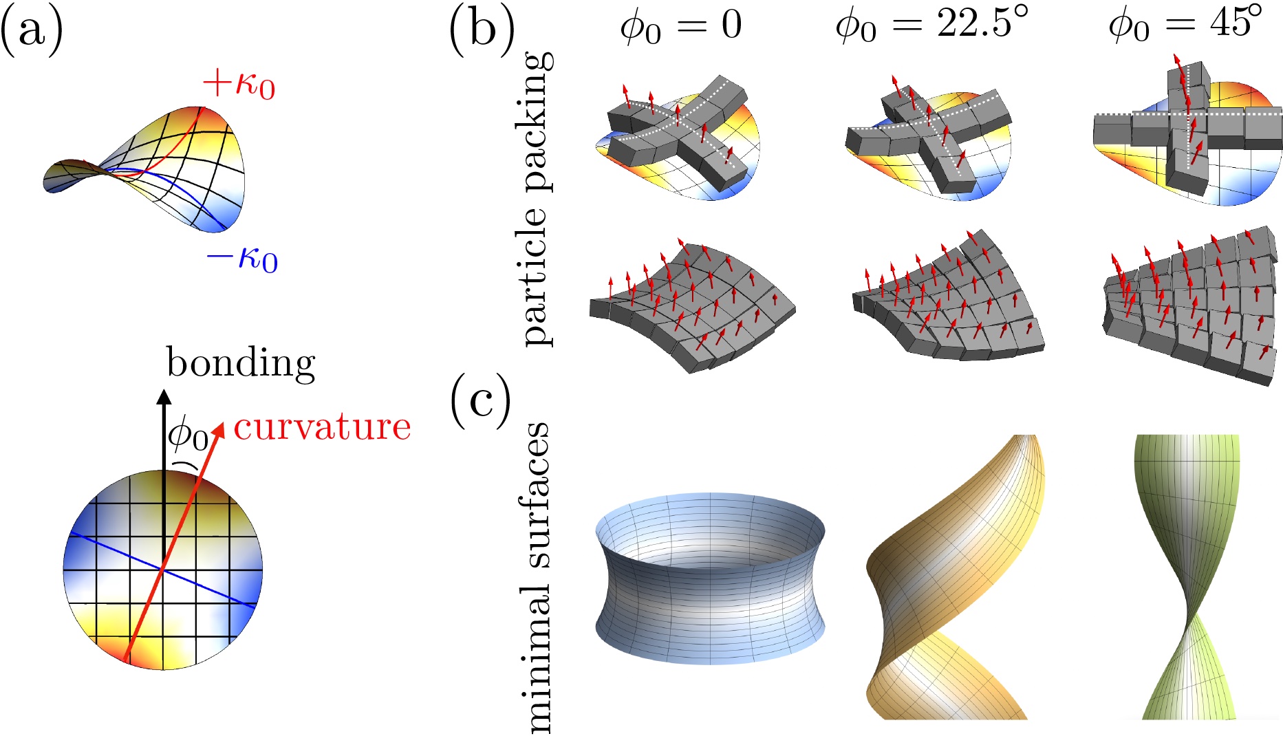
In this study, we aim to extend the understanding for frustration in hyperbolic, crystalline membranes from the level of phenomenological continuum descriptions to scale of shape-frustrated subunits from they form. Specifically, we introduce a new class of “saddle-wedge monomers” (SWMs) whose large scale interactions favor mesoscopic assembly geometries that map onto the existing continuum models. As shown schematically in Fig. 1, the variable shape of the SWM model encodes both tunable frustration (i.e. variable ) and also programmable relative directions of curvature with respect to close-packed crystalline (bonding) directions. This broader class of geometries has been recognized as equivalently frustrated, [46] and are related to the isometric (Bonnet) family of minimal surfaces spanning the catenoid and helicoid, [49, 50] parameterized by curvature angle between the crystalline rows and preferred curvature axis.
The aim of this discrete monomer study is several fold. First, we aim to understand how features of the geometry and interactions of building blocks govern the mesoscale shape and thermodynamics of optimal assemblies, and more specifically, determine the mapping of particle-scale properties onto parameters of the continuum description. Based on this, we analyze how the range of accessible self-limiting widths compare to size of the building blocks themselves. We show that the maximal size range of self-limitation is critically delimited by the range of cohesive bonds between monomers. Second, we analyze the responses to frustration that fall outside of linear elastic descriptions, more specifically the distinct roles of strain softening and yielding on size control, and the possibility of partial or incomplete bonding. We show that the former slightly depresses the range of thermodynamic self-limitation, relative to a purely Hookean elastic behavior, while the latter may be associated with a range of heirarchical ground states possible for sufficiently low temperatures.
The remainder of this manuscript is organized as follows. We first summarize a continuum scale description that is expected to capture the mesoscale structure and thermodynamics of SWM assembly, and then introduce the coarse-grained, discrete particle model. Next, we present numerical results from energy minimization calculations on the stress accumulation and flattening of energetic ground states of varying width. We then analyze the limiting case of the flattened state, the tube morphology, with numerics and continuum results considering the effects of anisotropic bending stiffness and strain softening, which are then used to construct the self-limitation phase diagrams in terms of SWM geometry and interactions. Next, we analyze deviations from purely linear-elastic behavior exhibited by the discrete subunit assembly, in particular, show that finite-range interactions generically imply the stability of internally-cracked or weakly-aggregated finite-domain morphologies in regimes where self-limited structures are favored over unlimited (bulk) structures. Finally, we conclude by discussing the relevance of the results to assembly at finite temperatures, implications for hierarchical assembly and we present preliminary evidence of assembly with molecular dynamics (MD) results.
II Models of frustrated hyperbolic ribbons
We first summarize the key ingredients and predictions of a continuum elastic model for assembly of hyperbolic, crystalline membranes followed by the introduction of discrete particle model of SWM whose assembly forms these frustrated morphologies.
II.1 Continuum Theory
Here we summarize a continuum elastic description for the frustrated ribbons formed by 2D crystalline membranes with a preference for negative Gaussian curvature shapes (see B for full details). The model, which we refer to as “narrow ribbon” (NR) theory, is essentially an elaboration of the original approach of Ref. [16], generalized to include arbitrary direction or curvature axes relative to crystallographic axis, as in Ref. [17]. The approach assumes slender assemblies with an assembly length and width such that : either ribbons of width much smaller than the (unlimited) assembly length in the orthogonal direction, or instead closed rings with width much smaller than the assembly circumference . The model includes three ingredients,
| (1) |
corresponding, respectively, to elasticity of extrinsic (i.e. bending) curvature, in-plane elastic strains of the 2D crystalline order, and the cohesive cost of free edges of the ribbons, dominated by the two longer edges (i.e. ). We consider the case of in-plane square-lattice order, and due to the energetics of strong (nearest neighbor) bonding along the lattice directions, assume that optimal ribbons form with their free edges along the lattice directions (i.e. either the local or direction of the ribbons, which are the low edge energy directions). Here we take the direction to be the long axis of the ribbon).
General considerations of the elasticity of anisotropic membranes, [41] imply a coupling between free energy to the curvature tensor curvature tensor of the membrane. According to the narrow-ribbon approximation, for which , we assume that curvatures are roughly constant across the width of membrane, and described by the values at the mid-line: along the ribbon’s length, along the width, and the off-diagonal element of the curvature tensor. Specifically our systems are described by the following extrinsic curvature elasticity,
| (2) |
where is the tensor of elastic bending constants and is the locally preferred curvature. The nearest neighbor binding square-lattice model leads to two non-zero elasticity constants,
| (3) |
for deformations that alter bending and twisting (of the tangent plane) along lattice rows; the remaining elastic constants are zero. The preferred (or “target”) shape can be written in matrix form,
| (4) |
where sets the magnitude of the preferred principle curvatures and parameterizes the angle between the lattice directions and the principle curvature directions (see Fig. 1). Notably, this preferred curvature targets minimal surfaces with a mean curvature and a preferred negative Gaussian curvature . While the original NR apporach of Ghafouri and Bruinsma [16] for chiral membranes corresponds to the case of , it was pointed out by Armon and coworkers that a larger family of target minimal surfaces (corresponding to the Bonnet family of minimal ribbons) are generated simply by rotation of the preferred curvature axis relative to its pitch axis. [17] We explore the implications of this broader control over frustrated shape for the design of the SWM and its ultimate assembly below.
The strain elastic energy takes the from
| (5) |
where and are the in-plane 2D strain and stress tensors for a square crystal. In-plane strains are coupled to the out-of-plane deflection the membrane through its intrinsic curvature, i.e. non-zero Gaussian curvature generates in-plane stress gradients. [51] As described in Ref. [16] and in the Appendix, these may be solved for long-ribbons assuming uniform stress along and constant Gaussian curvature resulting in an elastic cost that grows superextensively with width yielding,
| (6) |
where is the 2D Young’s modulus of the membrane.
The thermodynamics of the NR approximation follow from minimization of the total free energy density with respect to curvature and ribbon width and are summarized schematically in Fig. 2. For narrow ribbons (corresponding to small ), the ribbon adopts a shape close it is target hyperbolic shape, , so that the dominant elastic costs derive from in-plane strains. As a result, the stretching energy is super-extensive, growing faster than the assembly size , according to . In this regime, the optimal width is set (approximately) by the balance between in-plane stretching of the target shape and the edge energy (per unit area), , leading to an optimal (self-limiting) width that grows with edge energy and decreases with increasing target curvature, . When ribbons grow sufficiently large, the strain energy cost to maintain the preferred negative Gaussian curvature overwhelms the cost to unbend that assembly into an isometric (i.e. ) shape. Roughly speaking this occurs at a characteristic width scale,
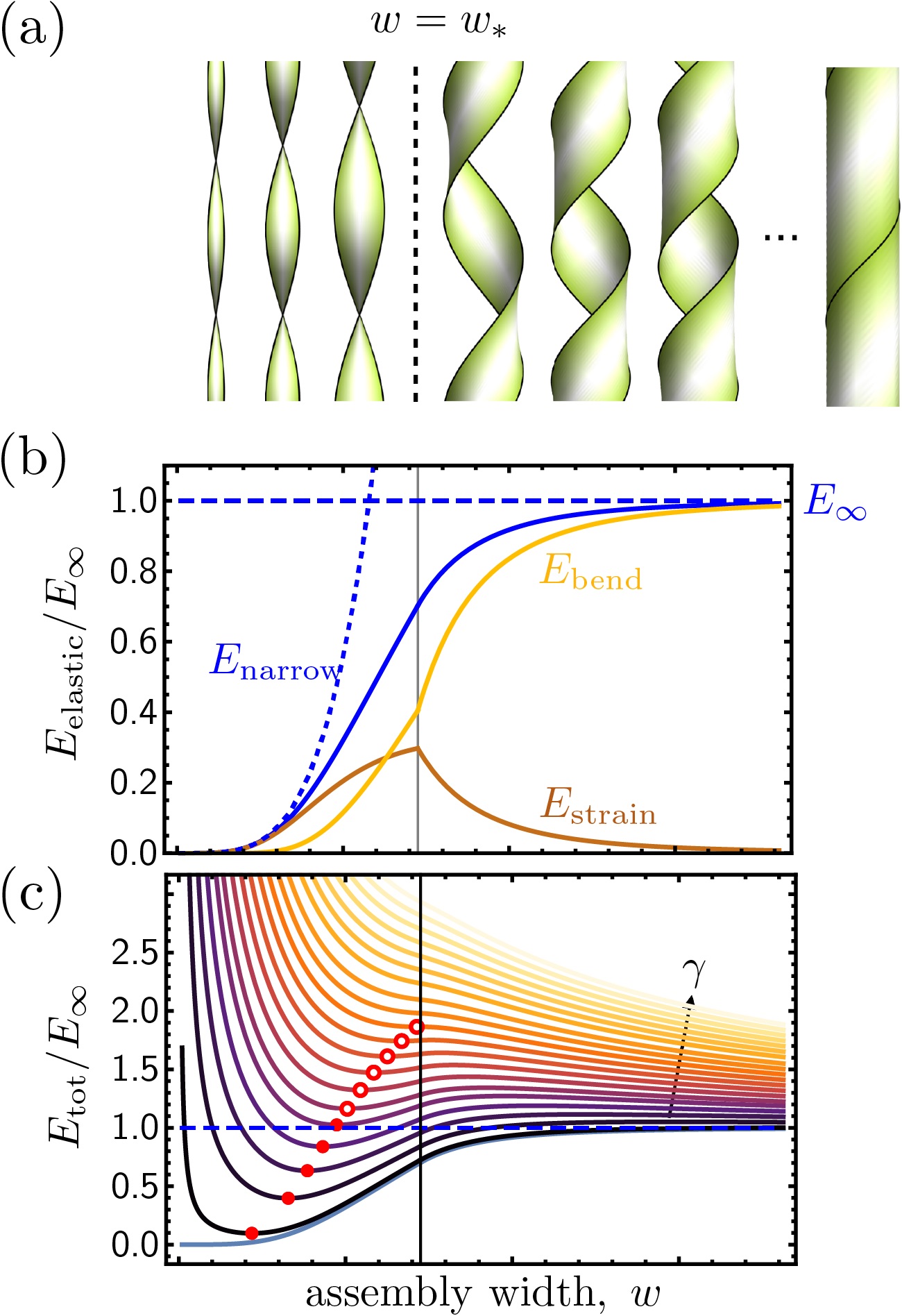
The model energy functional gives the (approximate) optimal shape and resulting elastic energy as a function of ribbon width (shown schematically in Fig. 2), when optimized over values of the curvatures. For small curvatures, as the curvature remains close to the preferred value. When ribbons reach a critical width , the strain energy cost to maintain the preferred negative Gaussian curvature overwhelms the cost to unbend that assembly to reduce , and the elastic ground states undergo a symmetry breaking bifurcation. For chiral ribbons (, this shape transition corresponds to a transformation from helicoids to spirals. In B we show that the supercritical shape transition occurs in GB theory for any value and for , leading to two different spiral equilibria (degenerate within GB theory). See for example the two stable branches for for in Fig. 11, which different in terms of helical pitch and radius.
In the limit , the the Gaussian curvature vanishes at the expense of bending spiral membranes into cylindrical shape with energy,
| (7) |
The flattened cylindrical shape is identified with frustration escape, as the assembly can grow without increasing elastic energy density. At large enough widths, the actual assembly will close up so that the flattened state is a closed tubule. Whereas the initial stretching cost is independent of , the expression for the flattening cost may depend on when the associated curvature moduli differ . One might naively expect that the larger flattening cost can extend the range of super-extensive elastic energy with growing size, and thus increase the range of size control; that is, the mechanical equilibrium would shift from self-limiting ribbon shapes to flattened, tube morphology roughly speaking when the ribbon elastic energy was equal to , so that would increase with increasing flattening cost. That is, based on this model, the mechanics of unbending the membrane away from its curved shape sets an upper limit to size scales where frustration can provide a thermodynamic limitation to the ribbon width. Analysis of equation 1 predicts a moderate reduction in the range of self-limitation with increasing curvature angle, , as a consequence of the mechanical flattening transition occurring at a smaller value of with increasing flattening cost . The central goal of this study is to directly assess variation of the range of frustration-limiting widths with , as the target shape is varied from catenoidal to helicoidal, for a discrete subunit model of hyperbolic, 2D crystalline membrane assemblies.
We note that the assumptions of the NR theory, namely that curvatures are sufficiently uniform across the width of ribbons, do not strictly hold across the full range of ribbons widths. This is because torque-free boundary conditions require a boundary layer of characteristic size proportional to , [52, 17, 53] so that through-width curvature variation becomes non-negligible for . We show this for an explicit solution for exact (boundary layer) solution below (for in Appendix B). This boundary layer correction modifies predictions of elastic energy, particularly in the large regime. Notably, finite-element calculations for ribbons suggest that boundary-layer corrections break the degeneracy between the two large- equilibria. These detailed corrections for intermediate- notwithstanding, we argue that the NR approximation works reasonably well for both the self-limiting (i.e. small) and the asymptotically flattened () regimes. The simple and analytically tractable solutions of the NR theory therefore provide a useful means to survey how thermodynamics of self-limitation varied with geometric and mechanical properties of the membrane in the continuum elastic description.
II.1.1 Discrete Model and Methods
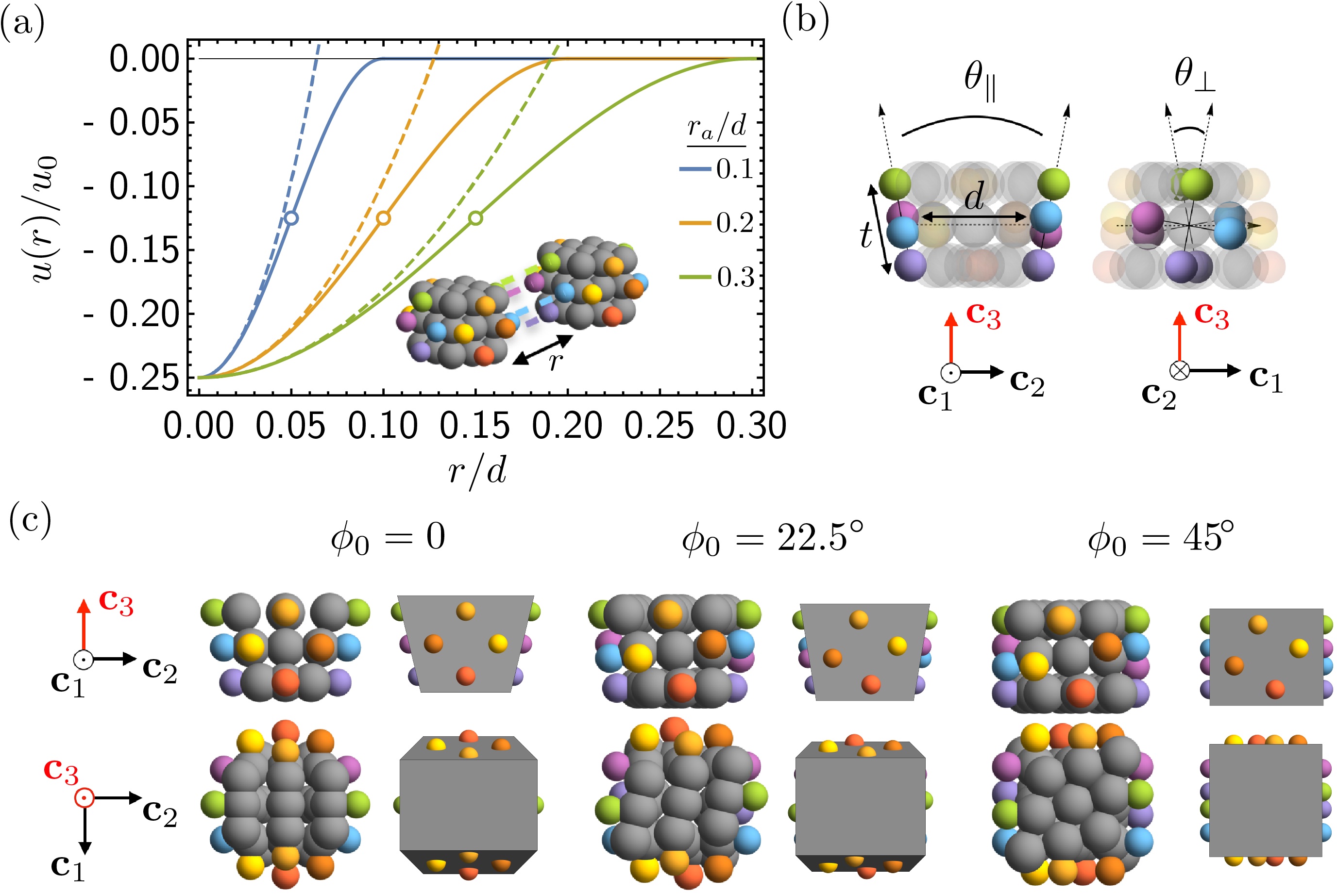
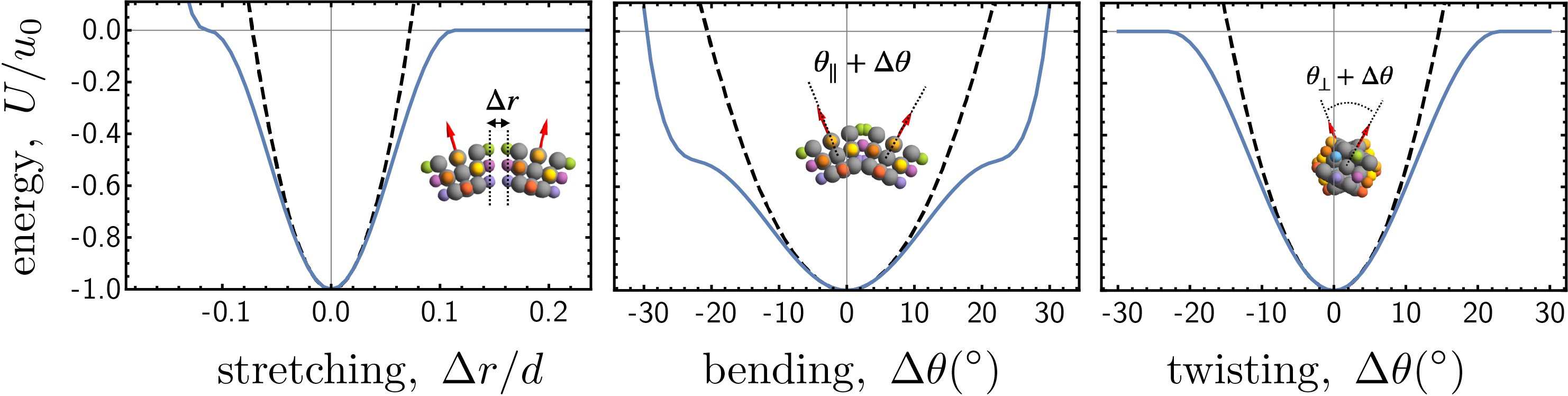
To connect discrete-monomer properties and design to assembly behavior, we developed a coarse-grained simulation model, building from a model previously developed to study microtubule assembly. [54, 55, 56, 57, 58] The saddle-wedge monomer (SWM) is designed for energy minimization and dynamical assembly simulation using the LAMMPS software. [59, 60, 61] The basic shape of the SWM is a “double-wedge” geometry: four binding faces that promote curvature of opposite signs in the orthogonal directions of the assembly, as illustrated in Fig. 3. The rigid monomer consists of 27 sites of a single type and purely repulsive interactions, surrounded by 16 attractive sites of 8 types, with the attractive sites arranged in a planar square on each of four bonding sides of the monomer. The square diagonal of the attractive sites on each face defines the thickness parameter that in principle may be used to tune the relative costs of changes in assembly curvature, bending, with respect to assembly stretching. For the results presented in this study, we consider the case . The monomer width is defined by the distance between respective centers of mass of attractive sites on opposite sides. For the attractive sites, pairwise binding only acts between sites of the same type on different monomers (as denoted by distinct colors of binding sites in Fig. 3). The repulsive sites interact according to a Weeks-Chandler-Anderson (WCA) pair potential, [62] and define the monomer excluded volume and shape in the low-energy minimized structures. Their arrangement, with coordinates, are described in more detail in Appendix A. The attractive sites on a given face are arranged in a plane parallel to the adjacent plane of repulsive sites on the monomer, so that pairwise attractions of all four sites are possible without overlaps from purely repulsive sites. The attractive site interactions each have the form of
| (10) |
where is the distance between interacting sites, is the interaction range and defines the potential well depth, such that the minimum energy for two monomers binding with all four attractive sites ideally placed is . Figure 3(a) shows the shape of the attractive interaction with varying interaction range. Full details of the monomer geometry and interactions are given in Appendix A. Importantly, , the range of interaction with respect to the monomer width, controls both the relative stiffness of the assembly via the elastic moduli defined below and also the strain necessary for a single bond to reach the point of yielding.
The orientational geometry relating pairs of SWMs bound together is defined in terms of the orthonormal frame associated with each monomer as shown in Fig. 3(b) with the first two directions pointing along neighbor bonding axes and the third direction point along the vertical (non-bonding) direction. The preferred binding geometry is determined by angles defined in a single rigid monomer. Attractive sites are arranged so that is the preferred angle between the axis of bonded neighboring monomers, when all four interacting sites on their respective faces coincide. The angle can be understood as a twist of binding directions (i.e. orientation of the square of attractive sites) around the axes connecting the SWM centers to their binding faces, i.e. by + or - around and , respectively (the twist sense in one bonding direction is chosen to be opposite that in the other direction to be compatible with membrane geometry of zero mean curvature). Taking the direction to be normal to the mid-surface of multi-particle membrane assemblies formed by SWMs, we can relate wedge angle and curvature angle to the target curvature tensor of the membrane as follows. Projecting the rotation sense between faces into the gives the preferred surface curvature times the particle width , or the angles and as illustrated in Fig. 3(b). Hence, orientational geometry of SWMs map onto preferred curvature of the form eq. (4) with target principle curvature
| (11) |
The attractive site arrangement defines both a monomer width that is approximately the preferred distance between neighboring monomers and a monomer thickness that controls the cost of bending deformations. As described in Appendix B, the effective elastic constants of membrane assemblies of SWM are determined by consideration of the local deformations on ideally bounded neighbors, imposed by distortions of a crystalline membrane. As shown schematically in Fig. 10, corresponds to stretching/compressing of inter-face spacing, while and correspond to dihedral and twist angle distortions between bound SWM. Modeling bound attractive sites as effective springs of stiffness leads to
| (12) |
Notably, as SWM are modeled as rigid bodies, eq. (12) highlights the role of the range of attraction in controlling the deformability of the assembly. Additionally, we note that the characteristic ratio of bend to stretch moduli is independent of interaction parameters, controlled only by the geometric thickness of the SWM particles. Last, it is important to note that, distinct from previously studied models of anisotropic bend-elasticity, off-diagonal bending is stiffer that bending along the lattice directions (i.e. . The greater twist stiffness relative to row bending, is generic consequence of attraction only binding, and has consequences in the thermodynamics of frustration escape for distinct values of SWM. As discussed further below, one consequence is the dependence of the flattening transition on ,
| (13) |
which is derived in Appendix B, eqs. (22)-(34). As we consider assemblies to form with open edges only along low energy directions in the bond lattice, it is straightforward to compute the edge energy per unit length
| (14) |
as (half) the ideal bond energy needed to separate membranes along their nearest neighbor direction.
To explore the the groundstate thermodynamics of size control of this model, the LAMMPS simulation software was used to minimize the energy of preassembled initial configurations. The LAMMPS minimize command was used with default, conjugate gradient method. Structures were successively minimized from a soft, relatively long-range interaction down to the target range of interaction, decrementing by and re-minimizing at each step. Additionally, the monomers were first minimized at a softer state where intra-monomer geometry was maintained with springs: (see appendix) minimizations with incrementing were run at intra-monomer bond stiffness and subsequently the minimization at the final value of was re-minimized at successive values and . The intra-monomer bonds are found to contribute negligible total energy compared to the total inter-monomer interaction potential energy (less than 1 part in ) after minimization at the larger bond stiffness. The final minimization was run until reaching a force tolerance of . Intermediate steps at higher and lower were run until either the same force tolerance was reached, or steps of minimization.
Multiple pre-assembled initial configurations were sampled with varying lateral dimensions corresponding to the ring or ribbon width, which is the number of monomer rows as measured in the shorter assembly direction. The initial configurations for varying width were cylindrical geometry and flat rectangular geometry for . The flattened tubule state’s energy was found from initially cylindrical geometry for longer tubes. For all starting configurations, monomers were arranged at a slightly dilated spacing of . For , the cylinder circumference was chosen to be , the cylinder length to be the target assembly size of monomers, with monomer bond directions aligned along the circumferential and longitudinal directions. For large-size energetics of all , cylindrical configurations were prepared with successively varying lengths of 100, 110, 120, 130, 140, and 150 monomers and bond directions along the cylindrical surface making an angle with the tube circumferential direction and axis. For , a rectangular geometry was used to sample smaller assembly size. The bonding directions were chosen in-plane and parallel to the boundaries of the rectangle, one side length was kept to be monomers while the other chosen to be the target size of monomers.
To determine optimal zero-temperature size of small-width assemblies, varying cylindrical ring or rectangular ribbon assembly widths were sampled up to where is the theoretical transition width from Eq. 13. Structures rendered in figures are shown with effective strain energy calculated from the average soft interaction energy, subtracting off the reference value of for each bond that was present in the initial configuration. Structures were analyzed to determine if any bond initially present in the starting configuration exceeds the yield point in the final relaxed state.
The total assembly energy is evaluated in terms of all pairwise interactions between sites on different monomers,
| (15) |
Following similar analyses of geometrically frustrated assemblies, [7] we define the excess energy as energy of the assembly relative to the cohesive bulk and edge energetics, and compute it by subtracting the ideal energy (of an unstrained bond) for every bond in the assembly
| (16) |
In the following sections, we consider the comparison of the excess energy of the discrete model to the continuum model predictions derived from equation 1.
III Results
III.1 Stress accumulation and flattening, beyond harmonic and isotropic elasticity
In this section, we compare simulated ground states of discrete-SWM assembly to the predictions of the continuum theory, illustrating how strain accumulation and elastic shape-flattening depend on on arrangement of attractive sites and the tapered shapes SWM binding.
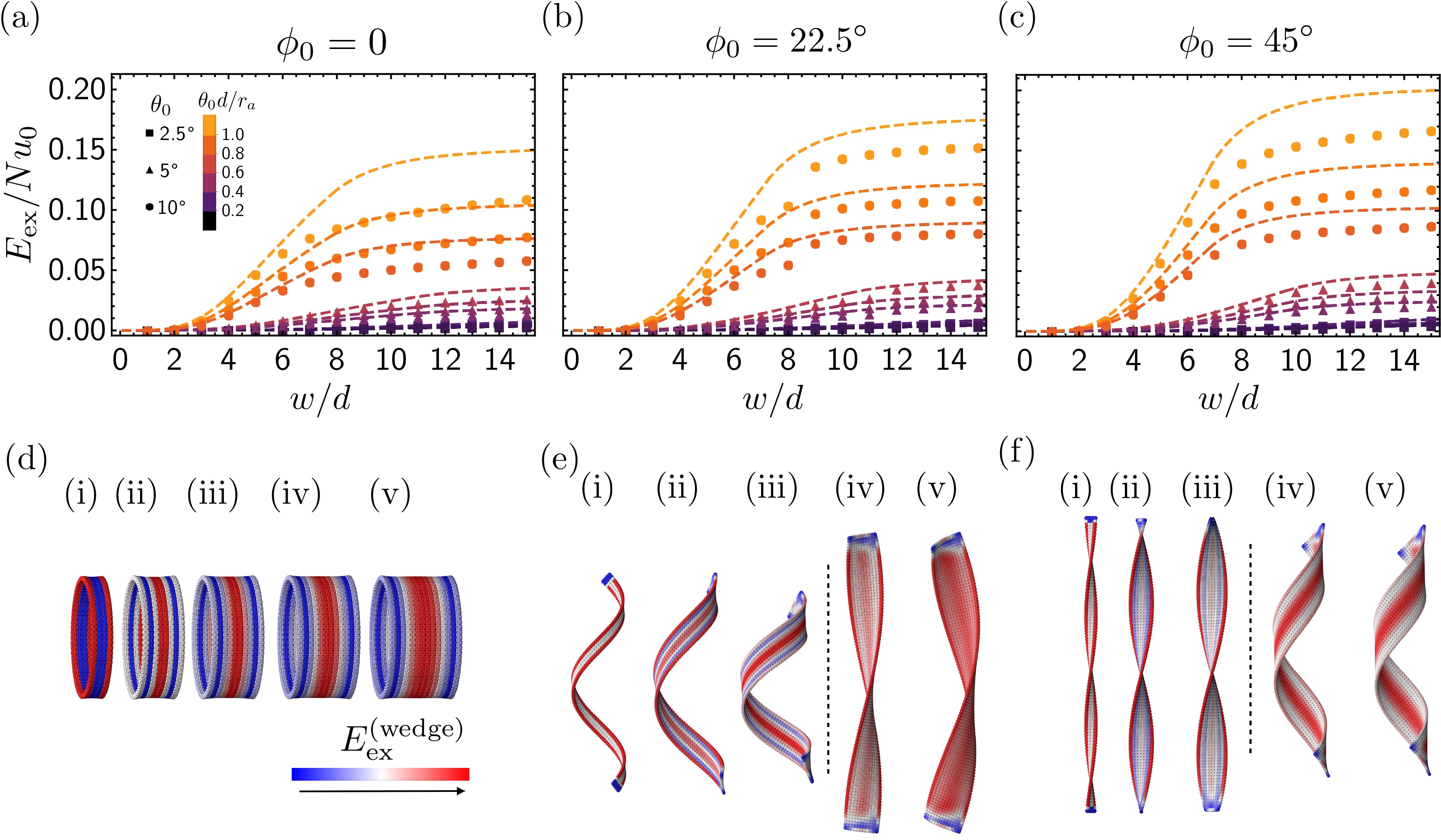
We focus on three values of curvature direction, with the closed ring that approximates a catenoid surface in the narrow limit, approximating a helicoidal ribbon in the narrow limit, and an intermediate case. The excess elastic energy computed from energy minimizations are plotted along with (narrow-ribbon) continuum model predictions in Fig. 4(a-c), for varying taper angle (), curvature direction (), and interaction range (). In each case, the continuum model accurately captures the excess energy in of discrete assemblies in the regime as well as the transition from super-extensive growth at small to extensive growth (i.e. saturated ) at large . Typical structures for the progression through the mechanical transition are rendered in Fig. 4(d-f). The cases for both show an apparently sharp shape transition between low- to high- values, as highlighted by the dashed lines in Fig. 4(e-f). In Fig. 11, we compare the predicted curvatures of from NR theory to shapes from the SWM ribbon minimizations in Fig. 11 for and . The general -dependence of simulated ribbon shapes is well-captured by the NR model, with abrupt changes in shape occuring near to the predicted values of . We note that our energy minimizations seemed to resolve only the larger pitch solution for large- cases of the , and attempts to seed and sample the lower-pitch branch were unsuccessful in finding these equilibria. This, combined with the observation from finite-element simulations [17] that the larger pitch branch has higher elastic energy, would seem to account for an apparent jump in the computed value for as the ribbon shape transitions from low- to high- equilibrium shapes (i.e. visible in between and 9 in Fig. 4b). In Fig. 2a-b, we show, nevertheless, that the basic dependence of on curvature angle is well captured by NR theory for both and ribbons. As there is a no symmetry breaking transition for catnoidal () membranes, the exact (boundary layer) formalism summarized in eqs. (36)-(47) shows that the shape evolution with increasing is fully-continuous for this case. No attempt to extract a shape-flattening size from simulated membranes was made.
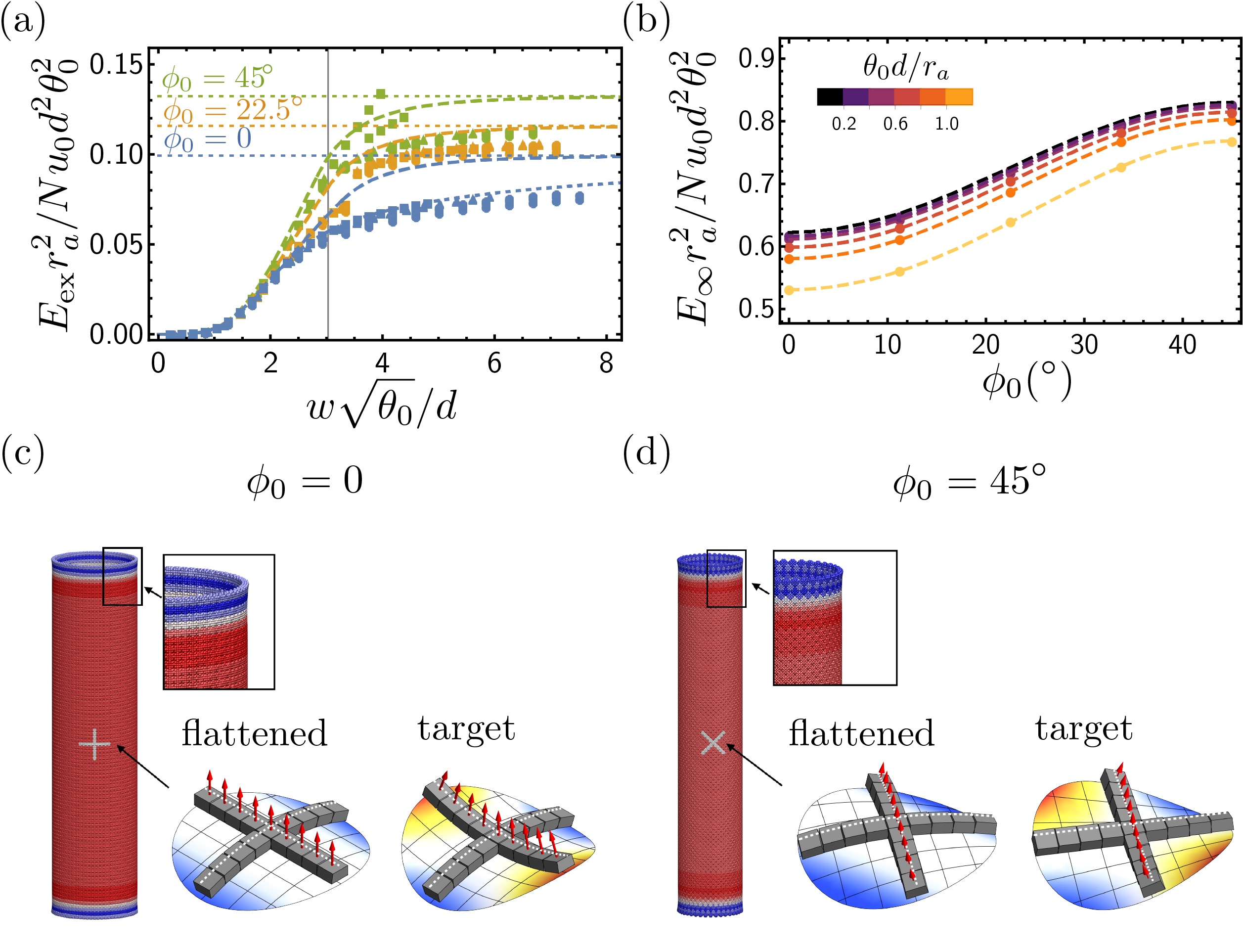
The comparison of discrete and continuum results for is made clearer when results are rescaled by the parameter combination (proportional to shape flattening energy) and rescaling widths by the characteristic elastic scale in Fig. 5(a). Here, the results show good agreement with the approximate continuum theory, plotted as dashed lines, for the limit of small . In this limit, the curves coincide for varying , showing the monomers are equivalently frustrated with independent of . Beyond the flattening transition, a noticable discrepancy is due to the continuum model approximation of uniform curvature, whereas a boundary layer forms for wider structures, lowering the elastic energy accumulation below the NR theory approximation. The exact boundary layer solution for the catenoidal case of , eq. (43), is plotted in 5(a), showing better agreement with the discrete SWM numerics. [63] Notwithstanding the discrepancy at intermediate scale, the flattening cost, , is the same in the narrow-ribbon approximation and boundary layer solutions as indicated on the right of 5(a). The difference in energies with for large is interpreted to be largely due to the differing values of . Some numerical results at small , in the case of were at unexpectedly large energy after minimization. This is attributed to the limited resolution of the minimization for the smallest values of , which reach low force tolerance to meet the stopping criterion without fully resolving the small residual strains in the structure.
The elastic energy due to shape flattening in the limit was further analyzed by minimization of tubule assemblies of SWMs. Closed tubules were prepared with monomer bonds aligned to minimize the bending energy, e.g. monomers with had bonds aligned parallel and perpendicular to the tube axis whereas for the bonding directions are at with respect to the tube axis. For intermediate values we analyzed the higher pitch helical geometry, but confirmed that both branches are degenerate in the limit (i.e. in the limit of vanishing boundary layer contributions). To account for the boundary layer relaxation of finite-length tubes, tubes of varying length were minimized, from to in increments of . The flattening energy was then found by extrapolation to infinite length. The results for five values of and varying are shown in Fig. 5(b). The dependence of flattening cost on via the anisotropic bending costs is captured by the harmonic approximation, eq. (7). However, results with significant strains associated with flattening, , relative to the range of interaction , show a reduction in the flattening cost due to strain softening as the interaction potential drops significantly below its harmonic approximation (see Fig. 3(a)). The modified predictions for flattening cost, plotted for varying as dashed curves in Fig. 5(b), are computed by minimizing attractive interactions over monomer orientations while enforcing uniform flattening with monomers maintaining spacing (i.e. numerical minimization of eq. (28) over subject to using the fully non-linear form of soft attractive potential). The flattening geometry for and is illustrated in 5(c), where the monomers in the tube are colored by excess energy to show the significant strain relaxation near the boundary and uniform strain in the interior. The comparison between (cylindrically) flattened and (hyperbolic) target geometry are illustrated for a cross array of SWMs blocks. Notably, this highlights that shape flattening for catenoidal SWMs () membranes generates row unbending, whereas for helicoidal SWMs () rows are untwisted from their target binding. The combined effects of shape flattening transitioning from unbending to untwisting as increases with a greater twist stiffness than row-bending stiffness (), leads to the () increase in elastic shape-flattening energy from catenoidal to helicoidal assembly observed in Fig. 5(b).
To summarize, ring and ribbon morphologies of SMWs exhibit ground-state energetics that are well-described by the NR theory as summarized in Sec. II.1. Additionally, we find that the wide-ribbon regime, where shape-flattening leads to saturation of the frustration cost, is also well described to a first approximation by the continuum model, eq. (7), although strain softening affects reduce this energy by up to for large wedge angles. Building from these results, we consider the zero-temperature thermodynamics of width limitation in the next section.
III.2 Self-limitation and range of size control
By including the effect of edge energy due to missing bonds at the assembly boundaries (i.e. the effects of ), we develop predictions for the possible equilibrium self limitation in the SWM model in the limit of zero temperature. The competition between surface energy and super-extensive elastic energy may result in minima in the energy-density landscape at finite . This minima is the self-limiting state, when its energy is less than the bulk flattened state , which in this case is a self-closing tubule. [7] In Fig. 6, typical data from minimizations for varying are shown. The corresponding linear-elastic, narrow-ribbon continuum model predictions are shown as dashed curves, along with flat dotted lines for the prediction of according to the strain-softened flattening (bend) energy shown in Fig. 5(b) . Typical SWM ground state structures are rendered in Fig. 6(d-f), for and .
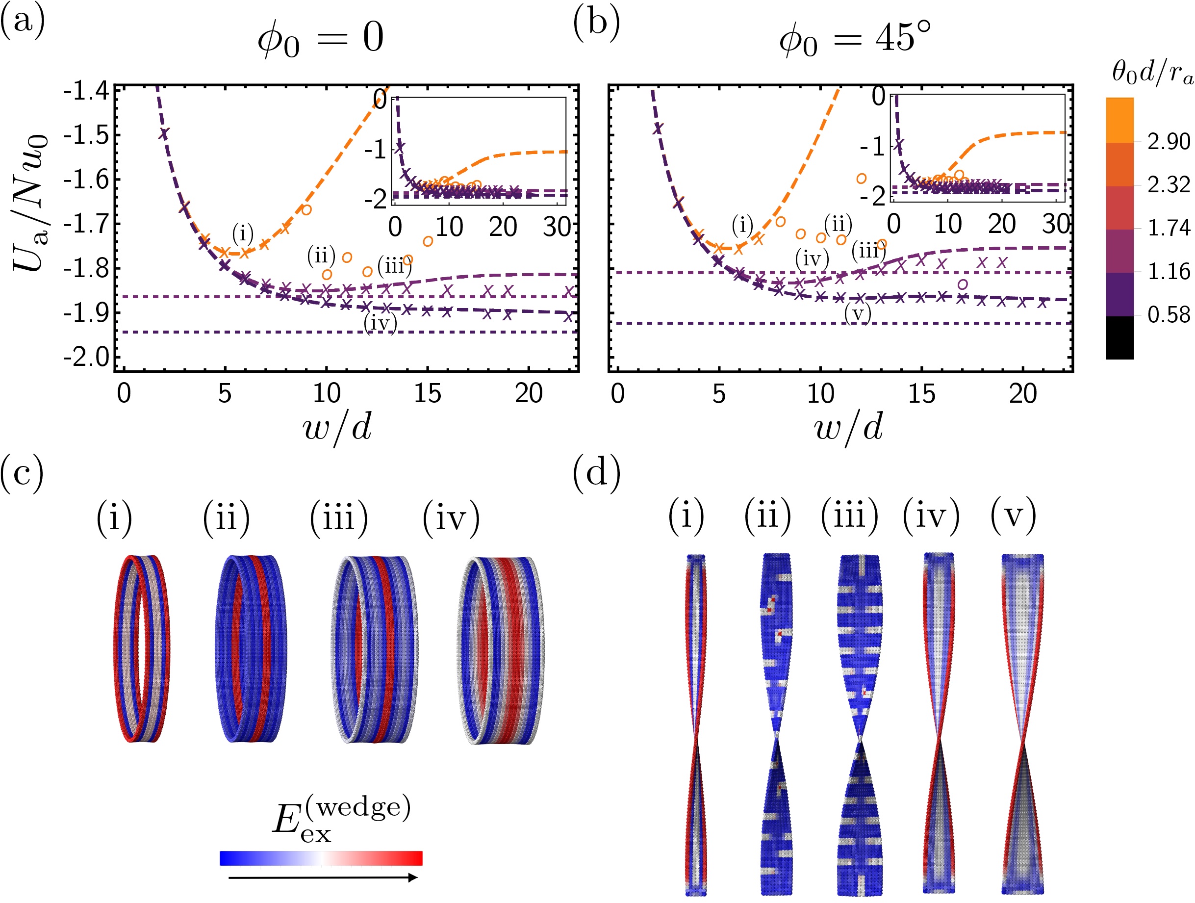
We start by noting the existence of a well-defined minimum at for the smallest attraction range (, or equivalently higher stiffness to cohesion ratio , for both catenoidal and helicoidal assemblies, with quantitative agreement between discrete SWM model and the continuum model. These minimal energy states fall well below the expected flattening energy from continuum theory, suggesting the thermodynamic ground state has frustrated-limited finite width 111 is not shown in Fig. 6 for the cases with smallest , when the corresponding strains exceed the inflection points of the attractive potential, .. Notably, and as discussed in detail in Section III.3 below, ground state structures for larger widths than the minimum fall off the curve predicted by the continuum theory, an effect which can be attributed to non-linear yielding of highly strained SWM bonds (locally yielded bonds appear as high-energy density bands in Fig. 6(c-d)).
For larger values of , the SWM ground states show general agreement with the predictions of the continuum model, including an optimal and energy substantially increasing for successively larger notwithstanding the instability associated with yielding for large enough structures. With increasing , which leads to effectively softer assemblies, the minimum becomes more shallow and eventually metastable to the defrustrated (i.e. ) state. Metastable minima can be resolved for increasingly soft assembly parameters, but cannot be resolved beyond despite minimizations extending up to . Self-limiting minima beyond are not predicted for the NR continuum model(see B).
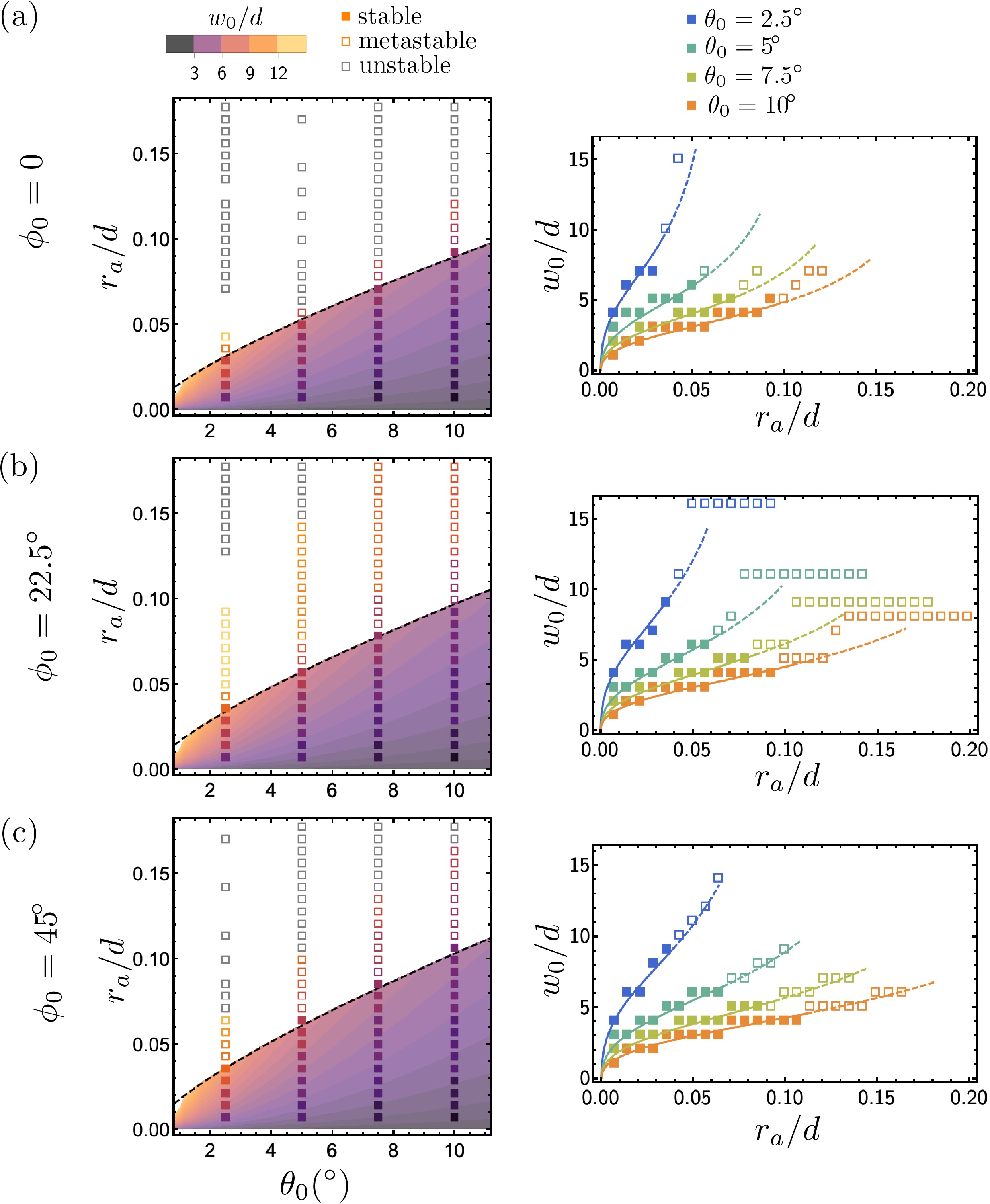
The predictions for equilibrium self-limiting size are presented in Fig. 7, for the full range of parameters investigated. Specifically, we denote SWM assembly self-limiting for parameters where we resolve a local minimum in the energy density and that minimum falls below the predicted shape flattening energy density. For this range of SWM taper angles (), we find the range of size control agrees with the continuum model (including strain-softening corrections to ), with equilibrium sizes up to monomer widths in length, consistent with 222The boundary layer corrected prediction for moderately larger sizes achievable for is not apparent, and may be too small of an effect to appear in the discrete model. Taken together, these show that anharmonic (i.e. strain-softening) effects of bonds in the discrete SWM model, which having little effect on the small, finite-width assembly energetics, lead to measurable reductions in the range of size control, relative to purely linear-elastic model descriptions.
III.3 Role of bond yielding in self-limiting assembly
The structures with large internal strains shown in Fig. 6 are a consequence of bond yielding, which occurs at the inflection point in Fig. 3. In general, models of self-assembly with geometric frustration and also with finite-range interactions can exhibit regimes where the internal strains associated with stress accumulation are greater than the interactions can support. This can result in a distinct mode of thermodynamic escape from self limitation, such as the nucleation of low-symmetry, cracked assemblies in curvature frustrated tubules.[21] In this regime, complex branched morphologies are expected, which are composed of stronger bound and elastically coupled regions, weakly bound together by partially yielded, yet at least slightly cohesive zones, as we observe in the partially yielded SWM ground states in Fig. 6(c-d).
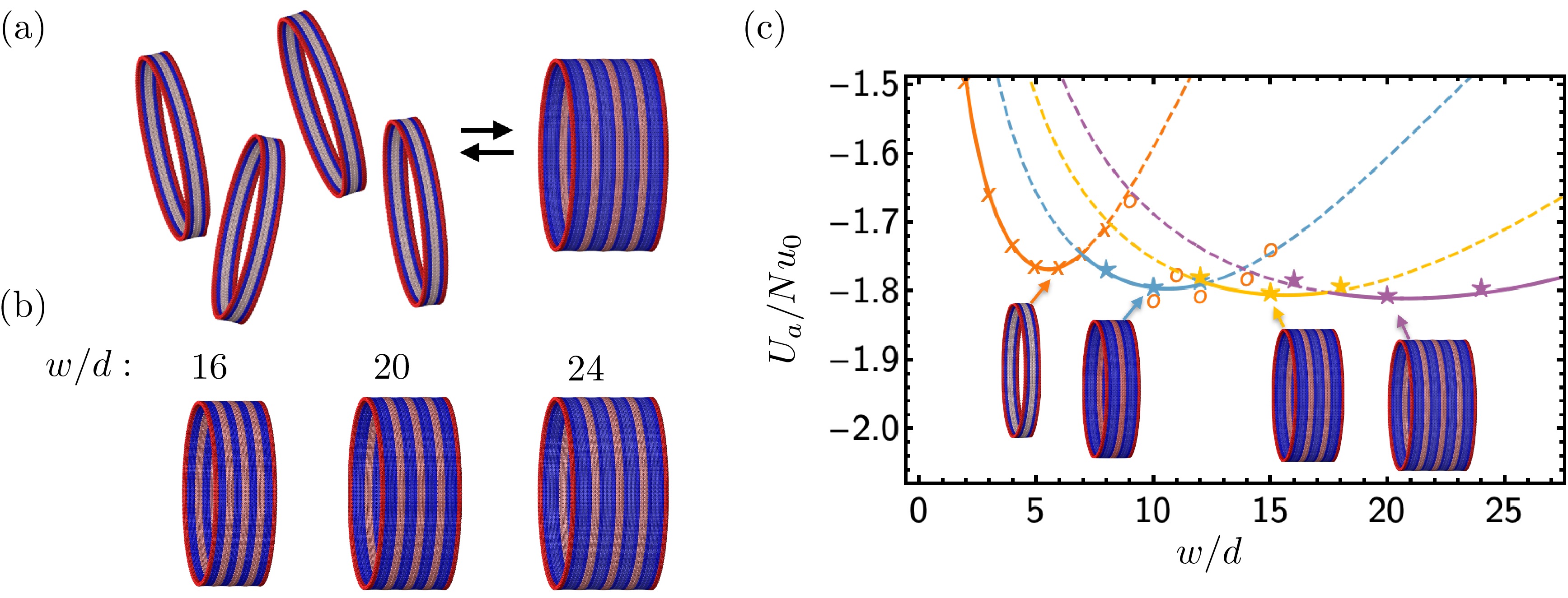
To further rationalize the energetics of yielded structures, we consider the simpler case of the low-energy yielded structure (ii) from Fig. 6(d), a catenoidal ring. Here, the yielded bonds are approximately in the middle of the structure, and the structure of total width is nearly twice the width of the self-limiting structure at width . We consider this structure as a composite of two non-yielded structures with yielded bonds acting as weak, partial bonding between the two structures. For this particular monomer geometry and parameters, we further explore the energetics of partial-bonding between self-limiting rings, with results presented in Fig. 8. Additional minimizations were conducted, starting with the minimized and non-yielded structures of width , 5, and 6. For each starting width new structures were prepared by arranging stacked copies of that structure, such that the copies did not interpenetrate but partial bonds were made, where one of the four attractors on a binding face coincided with its neighbor. After further minimization to the same force tolerance , the results are presented, with colors corresponding to the number of copies. The energetics of this composite ring morpholgies are well-described by an augmented model that uses equation 1 to describe the energies of the constituent non-yielded rings and fits a constant energy of to each of the partial bonds. These partially bonded structures are of lower net cohesive energy than the isolated, non-yielded structures.
More general considerations (i.e. at least weakly cohesive binding between elastically coherent self-limiting membranes) imply that such hierarchical morphologies are possible for any SWM assembly, at least at sizes sufficiently larger than , and generically such structures should have at least slightly lower total energy than the elastically self-limiting states (i.e. associated with the minimum in the energy density). However, due to the relatively weaker cohesive energy binding the structures at these yield bonds, it is expected these hierarchical structures may be broken up due to entropic considerations at sufficient high temperature, leading to an equilibrium state dominated by the elastically self-limiting morphologies identified in the phase diagram shown in Fig. 7.
IV Discussion and conclusions
In summary we have developed and studied a discrete SWM model of hyperbolic membrane assemblies with crystalline order. Detailed analysis of the minimal energy density morphologies is compared to predictions of linear-elastic, continuum theory illuminating the connection between microscopic features of the frustrated particles and their mesoscopic structure and thermodynamics. To conclude we discuss the implications of these results for the understanding and engineering of self-limiting assembly of geometrically frustrated building blocks.
IV.1 Controlling self-limiting dimensions through discrete building block shape and interactions
In this work, we identify the role of extrinsic geometry to shape equilibrium self-limitation via, , the angle relating bonding directions to the direction of rotation between bonded monomers. While the SWM model realizes equivalent stress accumulation, independent of , the elastic cost of escaping frustration through shape flattening can vary with when there is anisotropic bending cost (i.e. ) 333Notably, while the priori continuum analyses [17] are based on isotropic bending elasticity () the anisotropic case is fairly generic for purely attractive binding geometries, as twist deformations load all cohesive bonds in proportion to their distance form the rotation axis, whereas bend distortions only load bonds in proportion to projected distance to the neutral axis of bending.. For this reason, the extrinsic geometry has the potential to influence assembly energetics because relates the directions of preferred curvature to the bonding directions, determining the extent to which different modes of bending are activated with associated moduli . This is most clear in dependence of flattening energy on shown in Fig. 5b, which derives from the transition from unbending () to untwisting () in the flatten tubule geometry. A consequence of the increasing escape energy with is that the flattening size , and to a smaller extent , are predicted by NR theory to decrease with , as shown in Fig. 12c. A countervaling trend might be anticipated, based on the previously reported effects of the boundary-layer corrections on the shape-flattening tranisition [17] for equal bend and twist constants (), as shown Fig. 12d, which shows that instead increases by with . To assess whether the shape-flattening width should decrease with increasing as suggested by NR theory or whether boundary layer corrections dominate and lead to the opposite dependence, we extracted, we extracted the apparent (for ) and from SWM ground state simulations. Plotting these in Fig. 12c, we note that there may be a slight tendency for to decrease with , but this is obscured by the resolution limits imposed by discreteness of the changes in possible for the SWM model. We observe no measurable changes in the maximum self-limiting size with curvature angle. Hence, notwithstanding these two possible mechanisms for dependence, the size-range of self-limitation and stress-accumulation appear to relatively insenstive to intrinsic geometry of the SWM ribbon morphology.
Beyond the role of extrinsic geometry (i.e. the direction of curvature axes), the SWM model highlights the special dependence of self-limitation on the range of interactions via the stiffness associated with accumulating frustration costs to the assembly. Consistent with the generic predictions of continuum theory, results in Fig. 7 confirm that the maximum self-limiting width, , for a given block geometry is dictated by the flattening size scale, , simply because the energetics approach extensive scaling in this limit. In the simplest case, where interactions are purely cohesive, the ratio of bend to stretch ratio is controlled by the thickness (i.e. ) which itself is of order of the particle size . Hence, this suggests the maximum self-limiting size , which implies that the self-limiting dimensions that far exceed the size of the building block require small taper angles, . Additionally, the relations determining equilibrium size imply that that decreasing the degree of frustration through the wedge angle also decreases the range of edge energies for equilibrium, self-limited structures, which are characterized by the maximum edge energy . Notably, the ratio is a cohesive elastic length scale, which is most strongly dependent on the range (more strictly, the stiffness) of the cohesive interactions between subunits. Taken together, these two relations show that decreasing the degree of frustration through reduced wedge angle increases the size range of frustrated limited assembly, but does so at the expense of requiring narrowed range of interaction stiffness. In particular, thermodynamic self-limitation by frustration is only possible for , implying that self-selection on larger, multi-subunit dimensions requires increasingly shorter range (i.e. stiffer) cohesive interactions, which is consistent with the shift to smaller range with decreasing shown in Fig. 7.
Notably, this basic result is predicated on two assumptions: (i) that deformations in assembly primarily strain interactions while subunits are considered rigid and (ii) binding interactions are purely attractive. Relative to the case considered here, including additional deformability in the subunits themselves as in models of Refs. 22, 21, 6, the expectation may be to reduce the cohesive-elastic ratio below the (upper bound) limited by interaction stiffness, such that for any finite interaction range, inter-subunit deformability should only further depress the feasible size-range. On the other hand, it can be shown that more complex binding geometries, incorporating distinct spatial patterns of local attraction and repulsion can give rise to effective elasticity where , [20] thereby extending the elastic scale where shape flattening takes place.
Applying these elementary considerations to the experimental - gemini amphiphile system studied in Ref. 18 where width-dependent helicoidal ribbons morphologies were carefully characterized, we note, of course, that macromolecular subunits are both highly deformable and realize highly complex interactions. Nevertheless, we may assess the apparent effects of the likely ranges of interactions on the overall morphologies and likely equilibrium states. In these experiments, at early times, helicoidal ribbons are observed with mesoscopic pitches of order nm. Based on a considerations of local packing in the “twisted crystal” of amphiphiles, [18] It was estimated that nm, . Assuming the naive estimate , this suggests a shape-flattening size scale nm, and at this shape-flattening size, ribbons are of order sub-units across. Notably the estimate of is consistent with the fact that at longer times, as ribbons grow larger than this size range, they exhibit a shape-transition to spiral ribbons, consistent with the basic predictions of the continuum elastic theory, but ultimately suggesting that thermodynamic equilibrium does not correspond to a regime where frustration stabilizes the open-boundary helicoidal ribbon, presumably because the assembly is too ductile. This raises a basic question: presuming cohesive interactions govern the elasticity of assembly, how close might such a molecular system be to an equilibrium state of frustration limitation? Applying the estimate of the upper limit on interaction range for the gemini amphiphile membrane, we find . Notably, as subunits are molecular in dimension, this corresponds to a limiting interaction range that is sub-Angstrom, clearly much shorter range than what might reasonably be expected from van der Waals or hydrophobic interactions which bond the amphipillic subunits together. That interactions likely far exceed this range is consistent with the observed long-time growth of chiral amphiphiles assemlbies into shape-flattened tubules at long times, and more generally suggests that the possibility of frustration-limited assembly in molecular crystalline membranes may be difficult to achieve, if at all possible.
The restrictions placed on the elasticity and range of frustration accumulation by the interaction range suggest the feasible avenue for engineering self-limiting systems requires the combination of (larger) colloidal-scale particles bound by shorter range interactions. We point out a recent example of DNA origami particles 67, 32, 33 designed to be triangular subunits, nm in size with controllable inter-particle geometry, and large , assemblies driven by short-range base-stacking interactions, whose interactions range may be less than nm. [68] Beyond the requirement of shorter-range interactions relative to subunit size, frustration-limitation will also require engineered colloidal particles with the combination of precise geometry binding and also stiffness comparable to or exceeding that from the short-range stacking interactions.
IV.2 Role of finite interaction ranges: hierarchical aggregation
The results presented here show features of discrete systems that are not captured by the linear-elastic continuum description. Two possible features have been proposed to augment the continuum description. Firstly, we identified the relevance of nonlinear elasticity, which becomes relevant as the scale of deformations in the equilibrium structures becomes comparable with the range of interactions . Strain softening was shown to reduce the cost of tubule formation, with results presented in Fig. 5 that were well-described by the nonlinear elastic description of bending costs. Secondly, as the scale of deformations approaches the range of interactions, structures become mechanically unstable when individual interactions reach the yield point of the interactions. For our soft-binding model this corresponds to . The zero-temperature optimal size presented in Fig. 7 do not show a deviation from theory due to the breakup of bonds at high strains. However, the weakly-cohesive aggregation of otherwise elastically deformed, cohesive and finite assembly domains suggested here (as well as the low-symmetry internal cracking exhibited in the model of Ref. 21) constitute an alternative manner of escaping the self-limiting thermodynamic consequences of frustration, that will occur in any realistic, particle-based description of frustrated assembly.
In summary, if there is a minimal energy density at width , then two of these structures can at least weakly bind together (i.e. through partial yielding of cohesive bonds, or some set of bonds that do not transmit effects of frustration between domains) without introducing additional elastic costs into those two structures. Hence, it is straightforward to argue that at , the energy density of multiple weakly-aggregated domains of size will fall at least slightly below the single domain minimum. This simple argument suggests that generically even in states where a self-limiting domain minimum falls below the energy of the (smooth) shaped-flattened states, at sufficiently low temperature (and high concentration), self-limiting aggregates would be unstable to some condensed, multi-aggregate morphology that is effective unlimited in size, and points to the importance of finite- entropic effects in stabilize any putative regime of self-limitation.
IV.3 Modeling frustrated assemblies at finite temperature
While the core analysis of this study focuses on purely energetic ground states at , the conclusions detailed above imply some important open challenges for understanding frustrated self-assembly at finite temperature.
For one, while the frustrated assembly seemingly offers an attractive paradigm for controlling equilibrium self-limiting assembly through engineering misfit of building blocks, [27] we find that realizing such self-limitation at non-trivial size scales places important restrictions on the range of interactions. In particular, thermodynamic conditions where frustration-limited morphologies out compete shape-flattened (i.e. defrustrate) morphologies rely on attractive interactions between subunits that are short-ranged, ideally much shorter-range than the size scale of the SWM subunits. Using molecular dynamics to sample equilibration of discrete particle models, like SWM, in the self-limiting regimes faces additional challenges. Not only are the time scales to equilibrate such systems long, but stiff potentials require shorter time steps increasing the total computational cost. In addition, simulations of assembly of free particles will have a short capture radius, which will increase the simulation time. [69, 70]
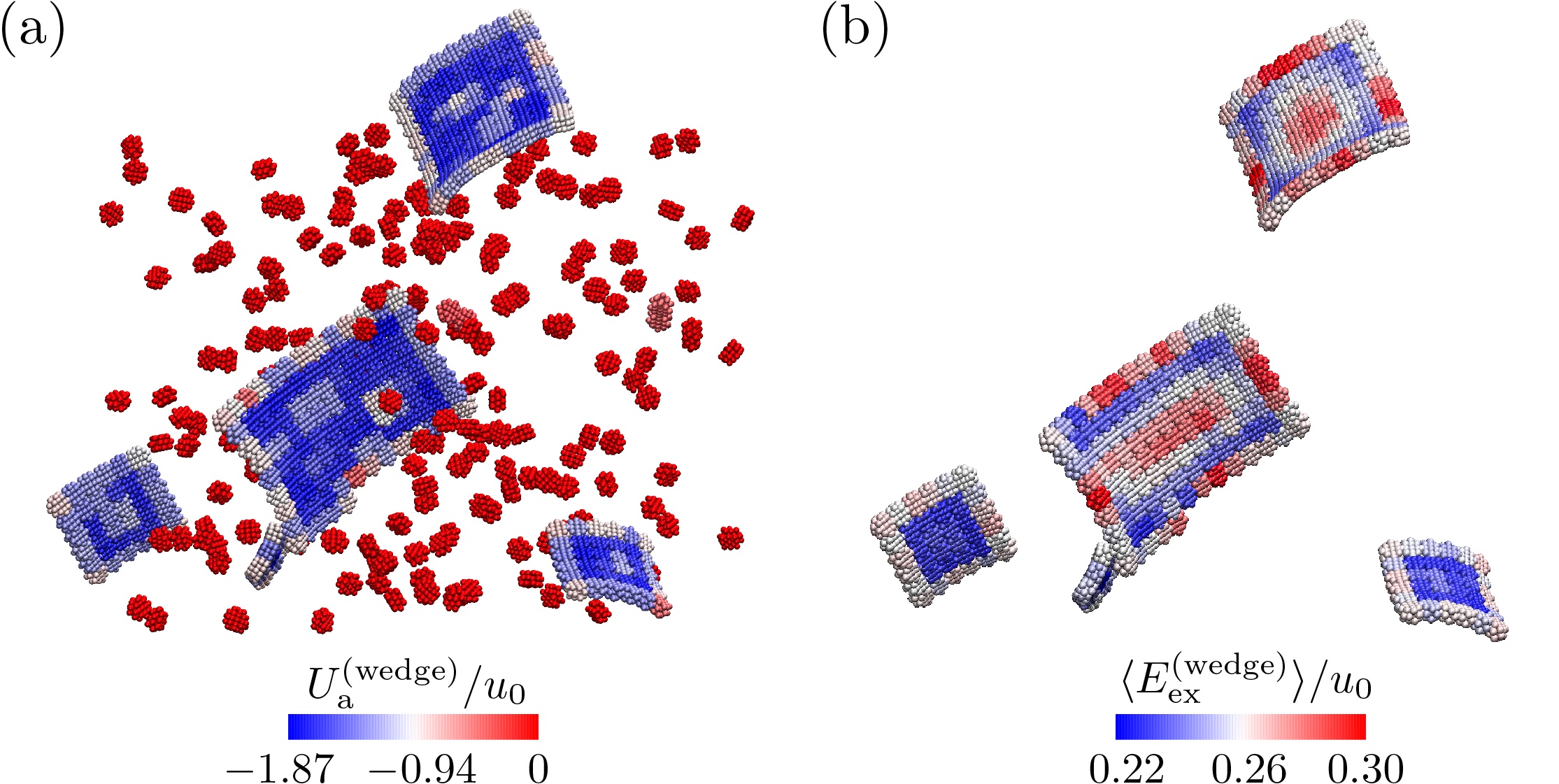
As a preliminary picture into the finite temperature self-assembly behavior of the discrete particle model, we carried out MD simulations of SWM model starting from disassociated configurations. In these simulations, 500 free subunits are randomly placed in the simulation box and the temperature is . The simulation system has 500 subunits at a density of , and the subunit parameters are (i.e. relatively large range) and . Fig. 9 shows that intial assembly does occur for this system in this time window, with wultiple rectangular assemblies have formed after 1 billion time steps. While further work is needed to determine the equilibrium structures and more fully explore the kinetics assembly, it clear that SWM parameters can be identified where MD simulation is viable.
Notably, while the free SWM simulations are free to sample much more irregular morphologies, the assembled clusters shown in Fig. 9(a) are mostly rectangular with boundaries aligned along the close-packed directions, which is favorable for cohesive assemblies to optimize the number of bonds formed for a given number of particles. This feature suggests the possibility that larger assemblies will maintain boundaries along the close-packed directions, which was implicit in the choice of pre-assembled structures of varying- that were generated for the results presented here. Coloring monomers by their respective interaction energy in Fig. 9(a) reveals that in addition to bonds forming and breaking, there are varying degrees of strain in the interior of each cluster, evidenced by patches of lighter color corresponding to more strained bonds. Further analysis revealed gradients in strain within the clusters assembled at finite , shown in Fig. 9(b). These more regular patterns of coherent strain gradients were extracted by averaging local binding in clusters over multiple time steps. Time sampling was chosen to be sufficiently short with respect to the lifetime of bonds but longer than the apparent correlation of elastic fluctutations or phonons within the structure. The appearance of these coherent strain gradients, which grow in magnitude with size, are consistent with the fact accumulation of frustration costs in the SWM model shape finite temperature pathways.
What remains to be determine are how these effects of strain accumulation also influence the kinetics of reaching equilibrium states, and further, whether and how finite temperature effects shift the expects phase boundaries between equilibrium self-limiting states and states of bulk assembly. Not only do we expect that especially soft and weakly frustrated systems to escape frustrated to unlimited, shape-flatted structures, but we also expect, based on the analysis described in Sec. III.3 that a low temperatures, otherwise frustration limited structures may condense or aggregate into (presumably low-symmetry) clusters held together by partially yeilding bonds. Hence, a further open challenge is to identify how non-linear features of the inter-particle binding that control yield, shape the critical temperature and concentration conditions at which translation entropy favors break-up (or melting) of heirarchical clusters into free, size-controlled aggregates.
Acknowledgements
The authors are grateful to M. Wang, B. Tyukodi and N. Hackney for valuable discussions on this work. DH and GG acknowledge support for this work through US National Science Foundation through award NSF DMR-2028885, as well as through the Brandeis MRSEC on Bioinspired Materials NSF DMR-2011846. This work was performed, in part, at the Center for Integrated Nanotechnologies, an Office of Science User Facility operated for the U.S. Department of Energy (DOE) Office of Science. Sandia National Laboratories is a multimission laboratory managed and operated by National Technology & Engineering Solutions of Sandia, LLC, a wholly owned subsidiary of Honeywell International, Inc., for the U.S. DOE’s National Nuclear Security Administration under contract DE-NA-0003525. The views expressed in the article do not necessarily represent the views of the U.S. DOE or the United States Government. Simulation studies of SWM model were performed on the UMass Cluster at the Massachusetts Green High Performance Computing Center and computers at Sandia.
References
- Kléman [1989] M. Kléman, Advances in Physics 38, 605 (1989).
- Sadoc and Mosseri [2006] J.-F. Sadoc and R. Mosseri, Geometrical Frustration (Cambridge University Press, Cambridge, 2006).
- Nelson and Spaepen [1989] D. R. Nelson and F. Spaepen, in Superconductivity Quasicrystals two Dimensional Physics, Solid State Physics, Vol. 42, edited by H. Ehrenreich and D. Turnbull (Academic Press, 1989) pp. 1–90.
- Wright and Mermin [1989] D. C. Wright and N. D. Mermin, Reviews of Modern Physics , 385 (1989).
- Grason [2016] G. M. Grason, The Journal of Chemical Physics 145, 110901 (2016), https://doi.org/10.1063/1.4962629 .
- Meiri and Efrati [2021] S. Meiri and E. Efrati, Physical Review E 104, 054601 (2021).
- Hagan and Grason [2021] M. F. Hagan and G. M. Grason, Reviews of Modern Physics 93, 025008 (2021).
- Schneider and Gompper [2005] S. Schneider and G. Gompper, Europhysics Letters (EPL) 70, 136 (2005).
- Meng et al. [2014] G. Meng, J. Paulose, D. R. Nelson, and V. N. Manoharan, Science 343, 634 (2014).
- Mendoza and Reguera [2020] C. I. Mendoza and D. Reguera, eLife 9, e52525 (2020).
- Hall et al. [2016] D. M. Hall, I. R. Bruss, J. R. Barone, and G. M. Grason, Nature Materials 15, 727 (2016).
- Grason [2020] G. M. Grason, Soft Matter 16, 1102 (2020), arXiv:1909.05208 .
- Efrati [2020] E. Efrati, Israel Journal of Chemistry 60, 1185 (2020), https://onlinelibrary.wiley.com/doi/pdf/10.1002/ijch.202000095 .
- Aggeli et al. [2001] A. Aggeli, I. A. Nyrkova, M. Bell, R. Harding, L. Carrick, T. C. B. Mcleish, A. N. Semenov, and N. Boden, Proceedings of the National Academy of Sciences 98, 11857 (2001).
- Achard et al. [2005] M. F. Achard, M. Kleman, Y. A. Nastishin, and H. T. Nguyen, European Physical Journal E 16, 37 (2005), arXiv:0403452 [cond-mat] .
- Ghafouri and Bruinsma [2005] R. Ghafouri and R. Bruinsma, Physical Review Letters 94, 138101 (2005).
- Armon et al. [2014] S. Armon, H. Aharoni, M. Moshe, and E. Sharon, Soft Matter 10, 2733 (2014).
- Zhang et al. [2019] M. Zhang, D. Grossman, D. Danino, and E. Sharon, Nature Communications 10, 3565 (2019).
- Serafin et al. [2021] F. Serafin, J. Lu, N. Kotov, K. Sun, and X. Mao, Nature Communications 12, 1 (2021).
- Spivack et al. [2022] I. R. Spivack, D. M. Hall, and G. M. Grason, New Journal of Physics 24, 063023 (2022).
- Tyukodi et al. [2022a] B. Tyukodi, F. Mohajerani, D. M. Hall, G. M. Grason, and M. F. Hagan, ACS nano 16, 9077 (2022a).
- Lenz and Witten [2017] M. Lenz and T. A. Witten, Nature Physics 13, 1100 (2017), arXiv:1705.08334 .
- Bruss and Grason [2013] I. R. Bruss and G. M. Grason, Soft Matter 9, 8327 (2013).
- Hall and Grason [2017] D. M. Hall and G. M. Grason, Interface Focus 7, 20160140 (2017).
- Paquay et al. [2017] S. Paquay, G.-J. Both, and P. van der Schoot, Phys. Rev. E 96, 012611 (2017).
- Li et al. [2019] S. Li, R. Zandi, A. Travesset, and G. M. Grason, Physical Review Letters , 145501 (2019), arXiv:1906.03301 .
- Grason [2017] G. M. Grason, Nature Physics 13, 1149 (2017).
- Berengut et al. [2020] J. F. Berengut, C. K. Wong, J. C. Berengut, J. P. K. Doye, T. E. Ouldridge, and L. K. Lee, ACS Nano 14, 17428 (2020).
- Tanjeem et al. [2022] N. Tanjeem, D. M. Hall, M. B. Minnis, R. C. Hayward, and G. M. Grason, Phys. Rev. Research 4, 033035 (2022).
- Glotzer and Solomon [2007] S. C. Glotzer and M. J. Solomon, Nature Materials , 557 (2007).
- Hueckel et al. [2021] T. Hueckel, G. M. Hocky, and S. Sacanna, Nature Reviews Materials 6, 1053 (2021).
- Sigl et al. [2021] C. Sigl, E. M. Willner, W. Engelen, J. A. Kretzmann, K. Sachenbacher, A. Liedl, F. Kolbe, F. Wilsch, S. A. Aghvami, U. Protzer, et al., Nature materials 20, 1281 (2021).
- Hayakawa et al. [2022] D. Hayakawa, T. E. Videbæk, D. M. Hall, H. Fang, C. Sigl, E. Feigl, H. Dietz, S. Fraden, M. F. Hagan, G. M. Grason, and W. B. Rogers, Proceedings of the National Academy of Sciences (in press) (2022).
- Hsia et al. [2016] Y. Hsia, J. B. Bale, S. Gonen, D. Shi, W. Sheffler, K. K. Fong, U. Nattermann, C. Xu, P.-S. Huang, R. Ravichandran, S. Yi, T. N. Davis, T. Gonen, N. P. King, and D. Baker, Nature 535, 136 (2016).
- Bale et al. [2016] J. B. Bale, S. Gonen, Y. Liu, W. Sheffler, D. Ellis, C. Thomas, D. Cascio, T. O. Yeates, T. Gonen, N. P. King, and D. Baker, Science 353, 389 (2016).
- King et al. [2014] N. P. King, J. B. Bale, W. Sheffler, D. E. McNamara, S. Gonen, T. Gonen, T. O. Yeates, and D. Baker, Nature 510, 103 (2014).
- Wicky et al. [2022] B. I. M. Wicky, L. F. Milles, A. Courbet, R. J. Ragotte, J. Dauparas, E. Kinfu, S. Tipps, R. D. Kibler, M. Baek, F. DiMaio, X. Li, L. Carter, A. Kang, H. Nguyen, A. K. Bera, and D. Baker, Science 0, eadd1964 (2022), https://www.science.org/doi/pdf/10.1126/science.add1964 .
- Oda et al. [1999] R. Oda, I. Huc, M. Schmutz, S. Candau, and F. MacKintosh, Nature 399, 566 (1999).
- Selinger et al. [2004] R. L. Selinger, J. V. Selinger, A. P. Malanoski, and J. M. Schnur, Physical review letters 93, 158103 (2004).
- Ziserman et al. [2011] L. Ziserman, A. Mor, D. Harries, and D. Danino, Physical review letters 106, 238105 (2011).
- Helfrich and Prost [1988] W. Helfrich and J. Prost, Physical Review A 38, 3065 (1988).
- Yan et al. [2019] J. Yan, W. Feng, J.-Y. Kim, J. Lu, P. Kumar, Z. Mu, X. Wu, X. Mao, and N. A. Kotov, Chemistry of Materials 32, 476 (2019).
- Grossman et al. [2016] D. Grossman, E. Sharon, and H. Diamant, Physical review letters 116, 258105 (2016).
- Blossey [2017] R. Blossey, Phys. Rev. E 96, 032405 (2017).
- Jeon and Hayward [2017] S.-J. Jeon and R. C. Hayward, Advanced Materials 29, 1606111 (2017).
- Armon et al. [2011] S. Armon, E. Efrati, R. Kupferman, and E. Sharon, Science 333, 1726 (2011).
- Wan et al. [2018] G. Wan, C. Jin, I. Trase, S. Zhao, and Z. Chen, Sensors 18, 2973 (2018).
- Selinger et al. [1996] J. V. Selinger, F. C. MacKintosh, and J. M. Schnur, Phys. Rev. E 53, 3804 (1996).
- Lidin [1990] S. Lidin, Le Journal de Physique Colloques 51, C7 (1990).
- Bonnet [1853] O. Bonnet, Comptes Rendus 37, 529 (1853).
- Seung and Nelson [1988] H. S. Seung and D. R. Nelson, Physical Review A 38, 1005 (1988).
- Efrati et al. [2009] E. Efrati, E. Sharon, and R. Kupferman, Physical Review E 80, 016602 (2009).
- Arieli et al. [2021] M. Arieli, E. Sharon, and M. Moshe, arXiv preprint arXiv:2105.00751 (2021).
- Cheng et al. [2012a] S. Cheng, A. Aggarwal, and M. J. Stevens, Soft Matter 8, 5666 (2012a).
- Cheng and Stevens [2014] S. Cheng and M. J. Stevens, Soft Matter 10, 510 (2014).
- Stevens [2017] M. J. Stevens, The Journal of chemical physics 147, 044902 (2017).
- Bollinger and Stevens [2018] J. A. Bollinger and M. J. Stevens, Soft Matter 14, 1748 (2018).
- Bollinger and Stevens [2019] J. A. Bollinger and M. J. Stevens, Soft matter 15, 8137 (2019).
- Plimpton [1995] S. Plimpton, Journal of computational physics 117, 1 (1995).
- Thompson et al. [2021] A. P. Thompson, H. M. Aktulga, R. Berger, D. S. Bolintineanu, W. Michael Brown, P. S. Crozier, P. J. in ’t Veld, A. Kohlmeyer, S. G. Moore, T. D. Nguyen, R. Shan, M. Stevens, J. Tranchida, C. Trott, and S. J. Plimpton, Computer Physics Communications 271, 108171 (2021).
- [61] http://lammps.sandia.gov.
- Weeks et al. [1971] J. D. Weeks, D. Chandler, and H. C. Andersen, The Journal of chemical physics 54, 5237 (1971).
- Tyukodi et al. [2022b] B. Tyukodi, G. M. Grason, and M. F. Hagan, (2022b), to be published.
- Note [1] is not shown in Fig. 6 for the cases with smallest , when the corresponding strains exceed the inflection points of the attractive potential, .
- Note [2] The boundary layer corrected prediction for moderately larger sizes achievable for is not apparent, and may be too small of an effect to appear in the discrete model.
- Note [3] Notably, while the priori continuum analyses [17] are based on isotropic bending elasticity () the anisotropic case is fairly generic for purely attractive binding geometries, as twist deformations load all cohesive bonds in proportion to their distance form the rotation axis, whereas bend distortions only load bonds in proportion to projected distance to the neutral axis of bending.
- Gerling et al. [2015] T. Gerling, K. F. Wagenbauer, A. M. Neuner, and H. Dietz, Science 347, 1446 (2015).
- Kilchherr et al. [2016] F. Kilchherr, C. Wachauf, B. Pelz, M. Rief, M. Zacharias, and H. Dietz, Science 353, aaf5508 (2016).
- Cheng et al. [2012b] S. Cheng, A. Aggarwal, and M. J. Stevens, Soft Matter 8, 5666 (2012b), arXiv:arXiv:1201.2328v1 .
- Hagan [2014] M. F. Hagan, Adv. Chem. Phys. 155, 1 (2014).
- LIFSHITZ et al. [1986] E. LIFSHITZ, A. KOSEVICH, and L. PITAEVSKII, in Theory of Elasticity (Third Edition), edited by E. LIFSHITZ, A. KOSEVICH, and L. PITAEVSKII (Butterworth-Heinemann, Oxford, 1986) third edition ed., pp. 1–37.
- Majidi and Fearing [2008] C. Majidi and R. S. Fearing, Proceedings of the Royal Society A: Mathematical, Physical and Engineering Sciences 464, 1309 (2008), https://royalsocietypublishing.org/doi/pdf/10.1098/rspa.2007.0341 .
Appendix A SWM design details and pairwise elasticity
This section details the SWM geometry, the interactions defined by repulsive and attractive potentials, and the resulting elastic response of a bound pair of monomers. The SWM geometry is designed so that pairs of bonded monomers prefer to adopt a target configuration with opposite rotation sense of neighbors in the two bonding directions, a discrete analogue to local curvatures of a minimal surface and the rotation of that surface’s normal vector. Here, the monomer’s coordinate frame is denoted by unit vectors and that are orthogonal and point in directions of bonding faces (see the coordinate frame illustrated in Fig. 3 in the main text) and is assumed to point along the local normal to the mid-surface spanned by the 2D assembly.
The rotation axes of the target configuration, relating a monomer’s coordinate frame to those of neighbors bonded in the and directions are, respectively,
| (17) |
In the target configuration, the frame of a monomer is related to its four neighbors’ frames by a displacement along the bond direction ( or ), rotation of angle about , and additional displacement of where is the neighbor’s frame after the rotation about . Here, is the nominal monomer width related to the actual monomer geometry and the arrangement its of attractive sites, detailed below. To leading order in , this transformation is a bending angle between neighboring monomers of projected along the bond direction and a twist angle of rotation about . The definition of enforces opposite sense of bending angle in the two bond directions, analogous to a minimal surface having curvature tensor with zero trace, and opposite sense of twist, which is true for a smooth surface that necessarily has symmetric curvature tensor.
The monomer design consists of an array of repulsive sites that define an excluded volume to monomer overlap, and attractive sites on four sides that determine the geometry of bound neighbors. This design is inspired by previous work on tubule-forming monomers in Ref. 54, 55, 56. Repulsive sites are of a single type and interact with the repulsive sites on other monomers according to the Weeks-Chandler-Anderson potential,
| (18) |
where is the distance between interacting sites, and are the reference distance and energy units chosen for simulations. For this study, the soft attractive interaction was chosen so that , consistent with attractive interaction strengths which favored finite temperature assembly in the tube-forming system. [54] The cutoff length yields a purely repulsive interaction that reaches zero energy and zero force at . The nominal monomer width is related to by , which follows from the attractive site arrangement specified below.
The arrangement of a monomer’s 27 repulsive sites can be specified in terms of the orthonormal coordinate frame for a given monomer with the bonding directions and . The arrangement varies with curvature angles to maintain separation between repulsive sites of bound neighbors that are close to the target configuration. Adopting indices that each take values , the repulsive site coordinates are
| (19) |
Reference: https://www.physicsforums.com/threads/wide-equation-in-revtex-4-2-is-overlapping-with-other-content.992578/
Repulsive sites in the midplane are arranged on the corners and edge centers of a square of side length , the repulsive interaction has range , so the attractive sites are chosen to sit approximately from the effective excluded volume of the monomer. Note that for the location of the repulsive sites do not lie along planar faces (as shown schematically in Fig. 3c), but more accurately instead skew quadralateral surfaces which deviate slightly from planarity. In Fig. 10, plots of pairwise energy under small deformations illustrate that repulsive sites do not play a role for the deformations up to the point of yielding (which can be roughly identified with the inflection point for energy vs. displacement), and for the parameters used in this work.
The interaction between attractive sites of the same type is given by the pair potential defined in Eq. 10 and there is no interaction between sites of different type. The 8 types at different locations (see Fig. 3) are used to control monomer face-face binding orientation. Based on the form of Eq. 10, the depth of each attractive potential pair is , so that an unfrustrated () bulk assembly has potential energy per monomer (there is energy per bond in the assembly, consisting of four attractive site pairs). There are four attractive sites on each side of the monomer (arrayed on a common plane), with corresponding types on opposite sides (see attractive sites colored by type in Fig. 3b-c).
The attractive sites on each side are arrayed in a strictly planar configuration, which is not generally the case for the repulsive sites arranged according to Eq. 19. For the side binding with respect to the direction, the four attractive sites have center of mass at with respect to the monomer center. From the center of mass, each attractive site is displaced a distance of in either the (i.e. vertically on the face) or (i.e. horizontally on the face), where and are the monomer’s coordinate frame after rotation about by .
The two attractive sites per side that are activated by both bending and twist deformations discussed below, displaced “vertically” from the center of each binding face, are defined using the monomer coordinate frame by
| (20) |
for indexing the four bonding directions and referencing sites above/below the monomer midplane. From the coordinates above, the magnitude of the displacement from the midplane is .
The attractive sites activated with twisting rotation about the bond axis but not bending rotations about the orthogonal direction, displaced “horizontally” from the center of the binding face, are defined by
| (21) | |||||
for indexing bond directions again and indexing sites displaced in opposite directions on the same monomer face. From these coordinates, the displacement of these attractors from the binding face center is .
While our elastic theory treats each monomer as perfectly rigid, SWM is enforced via harmonic potentials of the form where is the spring constant and is the rest length to maintain site separations according to the geometry above. Springs are applied between nearby repulsive sites, for all pairs with indices such that each index differ by at most one (i.e. springs between nearest, next-nearest, and next-next nearest neighbors). Each attractive site has springs enforcing its distance to the six nearest repulsive sites. All springs are kept at the same spring constant, which is incremented during energy minimization as detailed in Sec. II.1.1.
The attractive site positioning described above determines the relative cost of different elastic deformations of the assembly. In Fig. A10, the potential energy of a bound pair of monomers is plotted for deformations away from the optimal (target) pair configuration with energy , corresponding to all four attractive sites in contact with respective sites on the other monomer. Compression or stretching deformations, due to center-of-mass displacement by a distance that equally affects all four attractive sites, change the potential energy to leading order by with . Bending rotation, of an angle away from the preferred bend angle and about an axis through the horizontal attractive sites, displaces vertical attractive sites by a distance and changes the potential energy of the configuration to leading order by with . Twisting rotation of an angle away from the preferred twist changes the potential energy by with due to displacement of vertical and horizontal attractive sites. These three pairwise elastic constants determine the continuum model elastic constants relevant to stress accumulation in the assembly, discussed in the next section on the continuum theory. These constants depend weakly with and via and , which range from up to for , so that it approximately holds that . We therefore use a single elastic thickness parameter independent of monomer shape parameters.
Appendix B Continuum elastic model for anisotropic membranes
In this section, continuum theory predictions of wedge assembly energetics are derived, namely the harmonic elastic flattening energy , the harmonic elastic energy of ribbons and rings , characteristic shape-flattening size and numerical solutions for zero-temperature escape size . These show the role of anisotropy of the assembly, as presented along with the discrete-SWM numerical results in the main text: the in-plane stretching cost depends only on a single elastic modulus whereas the out-of-plane bending and the range of size control are dependent on the anisotropic bending costs and preferred direction of curvature .
The continuum model presented here follows previous theory that captured flattening of frustrated membranes [16, 46, 43] and the equivalent description of shape selection in frustrated elastic sheets. [45] The model predictions relevant to this study, including stress accumulation in the self-limiting regime (narrow limit), flattening transition and flattening cost are captured in an approximate description of the assembly geometry described by a single curvature tensor with components . This is an approximation to the shape of either slender ribbon or ring assembly, both with translational symmetry along the midline, and it is exact for the tubule-shaped membrane which is achieved in the limit of flattening without yielding. A correction to the theory that accounts for varying curvature throughout the assembly, in the closed-ring case , is detailed at the end of this appendix. To map the discrete wedge model to the continuum model, we additionally assume wedge monomer orientations stay aligned with the surface, so the monomer frame direction is aligned everywhere with the local surface normal of the assembly.
The elastic energy of the assembly is partitioned into two terms, applicable for the wedge assembly in the case of small deformations when the harmonic approximation to the attractive potential results in separate terms for stretching, bending and twist deformations of wedge bonds derived in the previous section. The continuum elastic energy is
| (22) |
describing respective elastic costs due to monomer spacing deviating from and gradients in monomer orientations deviating from the preferred angles and .
The stretching cost is derived from the in-plane response to given curvatures and the monomer preferred configuration, i.e. a square lattice with preferred spacing . For a 2D material with square symmetry, the full elastic energy has the form
| (23) |
where is the strain tensor and elastic constants. [71] The corresponding stress tensor satisfying that , is related to the strain by and where
| (24) |
is the Young’s modulus measured upon loading parallel to either of the square lattice close-packed directions. The strain depends on out-of-plane deflections, via where is the in-plane displacement field and is the deflection out-of-plane. [51] A condition for a single-valued displacement field, the compatibility condition, is derived from applying to the relations of strain to both the stress and the displacements. The special case of translational symmetry in the direction, so that gradients in vanish, implies are constants by mechanical equilibrium , and compatibility becomes
| (25) |
where is the Gaussian curvature, with the relation to under the small-slope approximation. One finds the constants of integration that fully determine by minimizing over . Thus, the continuum model expression for stretching cost of slender ribbons or rings of length and narrow width is
| (26) |
We note that different prefactors appear in the same “narrow-ribbon” constant curvature calculations in other Refs. [43, 9, 18, 72], with specific Poisson ratio dependence, while our result in eq. (26) is inagreement with the (Poisson ratio-indendent) results of Refs. [16, 8]. We believe this discrepancy to derive from the neglect of vanishing longitudinal net stress along the ribbon (i.e. ) in the former group of references. The fit-free agreement of numerical results presented in Fig. 5 with the eq. (26) is consistent with this conclusion.
The Young’s modulus is the response to uniaxial stress applied in or coordinate directions, which are the bonding directions for the wedge model. The stretching response of the assembly then derives from the pairwise stretching of bonds described in the previous section, so that taking the continuum limit of a square lattice of springs with spacing , and extension along the bond direction, we have form of the the Young’s modulus given in eq. (12), .
The harmonic bending energy is also anisotropic. Tme most general form for the harmonic bending energy of membranes with anisotropy arising from distinct in-plane directions is given
| (27) |
equivalent to the most general form given in Helfrich and Prost [41], where it was emphasized that arises from molecular chiral asymmetry despite the achiral symmetry of the curvature quadratic form. The case of , with zero Gaussian curvature modulus was considered in Ref. 16 to explain chiral amphiphile assemblies. The more general case with varying was connected to internally stressed elastic solids in Ref. 46, where could be realized from stretched bilayers without material chirality, instead the assignment of via the boundary breaks symmetry and results in chiral shapes. The interaction specificity in the wedge model distinguishes bonding in the two lattice row directions, so wedge monomers are notably chiral for the case . If the attractive sites were arranged differently on the and oriented faces, the monomers could in principle have . The saddle-wedge design presented in this study has , with consequences for size control derived below. The role of Poisson’s ratio in the elastic sheet description of Refs. 43, 46 can be mapped to the Helfrich-Prost bending energy functional of the assembly above, effectively modulating both and . Here, we further develop the analysis with varying but constant preferred principal curvatures set by .
The bending elastic cost derives from the monomer attractive site interactions and the target pairwise configuration derived in the previous appendix. Assuming monomers have their frame direction aligned with the assembly surface normal, the deviation from preferred bend angle in the direction is taken to be , in the direction and the deviation of twist angle in either direction is . The cost of bend deformations for a single SWM with these local curvature values, is then the sum of potential energy from displacements of the two vertical attractive sites in either direction and of the four horizontal attractive sites
| (28) |
where the attractive potential is, again, when . Summing over all wedges (per unit area ) and assuming small deformations, and the bending energy takes the (harmonic) form of Eq. (2) with the moduli given in Eq. (12). Thus, the SWM design has anisotropic bending constants, with arising from the configuration with two attractive sites displaced under bending and all four attractive sites displaced under twisting deformation.
The NR theory elastic cost of the flattened state is found by optimizing under the constraint that the curvatures describe a cylindrical surface with zero Gaussian curvature, . Thus, monomers arrange with preferred spacing and there is zero stretching energy so (minimized over subject ). Minimization subject to leads to two degenerate solutions, shown Fig. 11 for and . In the harmonic approximation described by equation 2, one finds that both the optimal shape and energy depend on both and the twist-bend anisotropy. When (as studied in the case of Ref. [17]), one of two equal-energy shape solutions is , , and , giving energy that is independent of .
For the present case of SWM assembly, were , one of the two shape solutions is
| (29) |
corresponding to (Hookean elastic) continuum result for flattening energy,
| (30) |
and more generally,
| (31) |
This is the expression plotted in Fig. 5b for the harmonic limit . To get the corrected result accounting for non-linear strain softening of the potential, also plotted in Fig. 5b, eq. (28) was numerically optimized over with to produce the curves with nonlinear bending energy and nonzero .
The full NR elastic energy for the SWM model is the sum of the narrow-ribbon limit and the harmonic approximation of evaluated with constant curvatures everywhere:
| (32) |
which is then optimized over the curvatures for varying .
When , the branches of the equilbriumsolution are characterized by a length associated with the transition from unflattened shape at small with zero mean curvature to one of two flattened branches of degenerate energy with analytical forms given in Ref. 43 up to a constant arising from different approximations for stretching energy. One can verify that the energy in both narrow and wide branches is independent of . In general, we find
| (33) |
and the specific presnet case of the SWM model with anisotropic curvature moduli,
| (34) |
so that increasing , i.e. increasing preferred twist curvature, results in the flattening at a smaller characteristic width. The energy of the wide branch has the form,
| (35) |
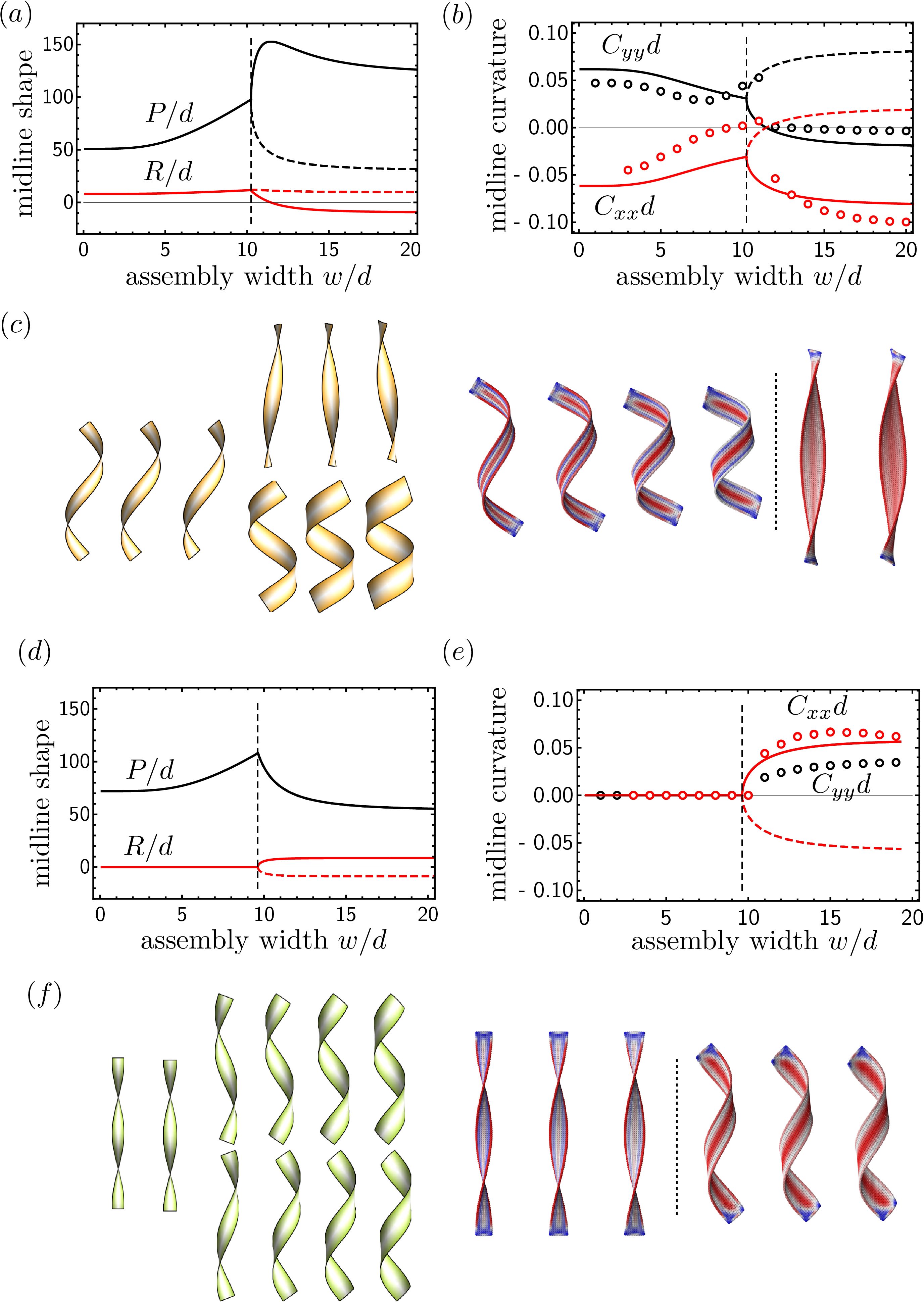
The wide branch approaches the harmonic approximation to the flattening energy that itself depends on . The decay of the residual energy has the consequence that there is no surface energy such that the model energy density has a minimum in the wide branch. Because of this, is strict upper bound for the optimal size that can be obtained from this theory, and the analytical expression for decreases with despite the increasing flattening cost with for this model.
Local minima exist for any in the narrow branch, with a discontinuity in the second derivative of present at . In the narrow branch, the maximum self-limiting size is taken to be the minimum to at which the local minimum has equal energy to the bulk tube state. That is, following the framework in Ref. 7, self-limiting size is achievable when the accumulant is increasing, . This is found to always occur at a size smaller than in the model. The solution satisfying from numerically solving for the narrow branch is plotted in Fig. 12.
In general, a more accurate description of shape solutions with varying curvatures is expected to include a boundary layer that develops as , so the residual energy of wide ribbons allows for locally optimal sizes at any width. The calculation at the end of this section, however, shows that the correction in is small for . The boundary layer correction may have an effect on the dependence of with : even for the isotropic case , the boundary layer length was shown to scale depending on the tangential curvature of the flattened ribbon in Ref. 52, and as a consequence increases with increasing supported by finite-element numerical results in Ref. 46. The weak dependence of on in the numerics presented in this study may be affected by the effect captured in this boundary layer scaling : increasing decreases tangential curvature along the boundary of the flattened ribbon. Whereas the initial elastic energy growth depends only on the intrinsic geometry, the extrinsic geometry, , can affect the energetics, and range of equilibrium size control, via the mechanics at the boundary.
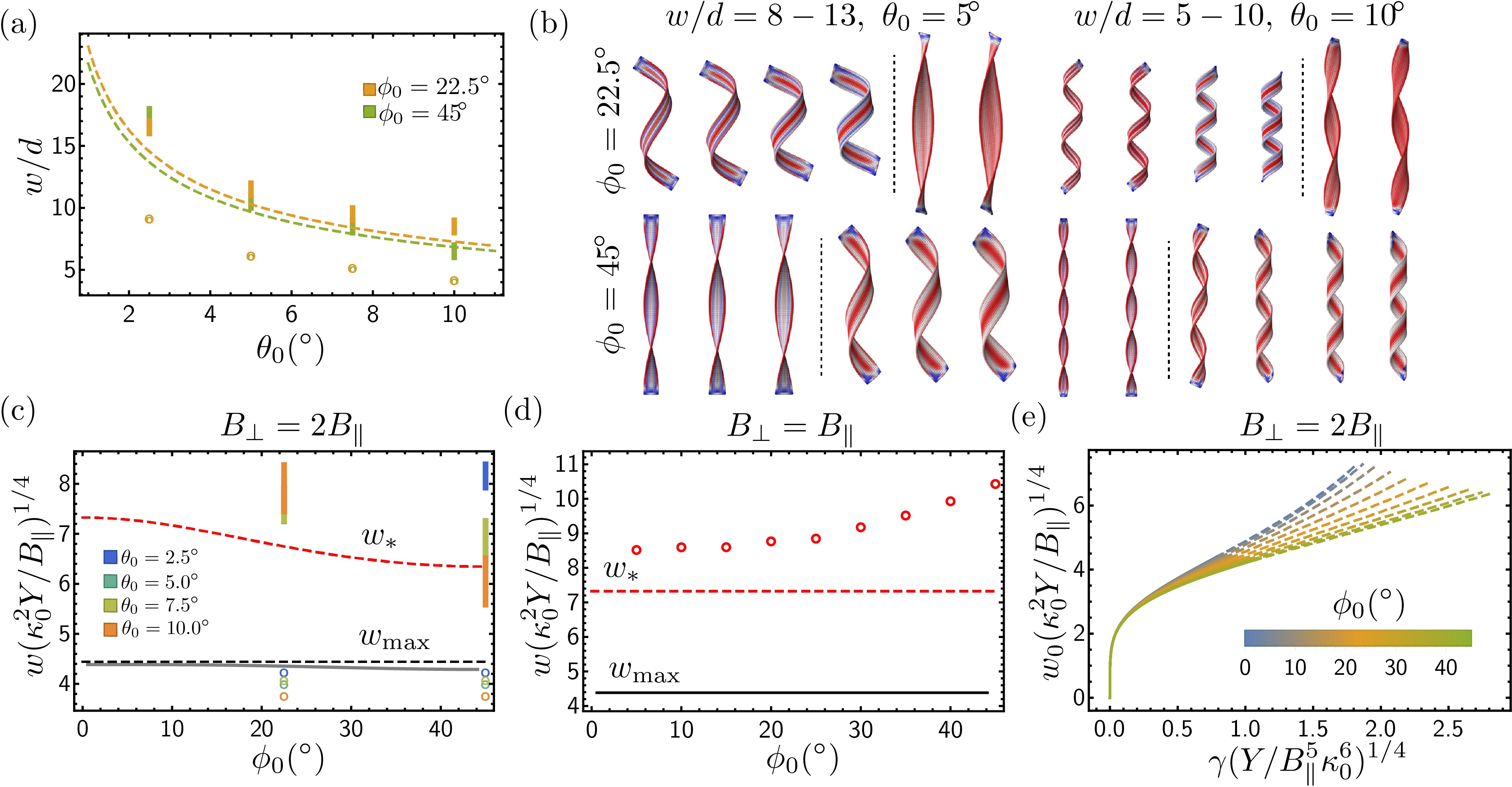
For the case of the ring assembly we derive the boundary layer corrected solution starting from harmonic elastic energy described by equations 23 and 2, limited to axisymmetric shapes, i.e. translation along the coordinate. Here, the optimal shape is allowed to adopt in-plane displacement transverse to the ring and out-of-plane displacement in the radial direction, expanding around a cylindrical shape with principal curvature with linearized solution for . One finds that
| (36) | |||||
| (37) | |||||
| (38) | |||||
| (39) | |||||
| (40) | |||||
| (41) |
and defining characteristic length :
| (43) | |||||
| (44) | |||||
| (45) | |||||
| (46) |
Where the limit on the last line is in agreement with the result of the uniform curvature approximation. Following the accumulant analysis of Ref. 7, the maximum possible self-limited size becomes
| (47) |
For , , and approximately greater than from the uniform curvature result, as shown by the comparison in Fig. 12. In this way, corrections to the model results with the uniform curvature approximation are expected to be small for the energetics up to . A similar result for the case of was included in Ref. 53.