Full-Duplex Transceivers for Next-Generation Wireless Communication Systems
Abstract
Wireless communication systems can be enhanced at the link level, in medium access, and at the network level when transceivers are equipped with full-duplex capability: the transformative ability to simultaneously transmit and receive over the same frequency spectrum. Effective methods to cancel self-interference are required to facilitate full-duplex operation, which we overview herein in the context of traditional radios, along with those in next-generation wireless networks. We highlight advances in self-interference cancellation that leverage machine learning, and we summarize key considerations and recent progress in full-duplex millimeter-wave systems and their application in integrated access and backhaul. We present example design problems and noteworthy findings from recent experimental research to introduce and motivate the advancement of full-duplex millimeter-wave systems. We conclude this chapter by forecasting the future of full-duplex and outlining important research directions that warrant further study.
1 Introduction
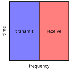
For more than a century, wireless communication systems have almost exclusively operated in a half-duplex fashion, where transmission and reception of radio waves have typically been separated—or orthogonalized—in the time domain, frequency domain, or both. Put simply, signals transmitted or received by a traditional half-duplex system exist in different frequency bands or at different times, referred to as frequency-division duplexing (FDD) and time-division duplexing (TDD), respectively. Half-duplex operation is necessitated by the manifestation of self-interference (SI) when a transceiver attempts to receive signals while simultaneously transmitting in the same spectrum. In most cases, SI is many orders of magnitude stronger than a relatively weak signal-of-interest (or desired receive signal), which has presumably propagated tens or hundreds of meters. This makes it virtually impossible to accurately recover the desired receive signal from their combination without taking additional measures to mitigate the effects of SI ashu_inband_jsac_2014 ; kolodziej_techniques_2019 . By receiving in neighboring frequency spectrum or on a separate time slot as its transmissions, a half-duplex transceiver can avoid inflicting SI onto a desired receive signal, hence the usage of FDD and TDD.
By their nature, FDD and TDD both consume radio resources by dedicating time-frequency resources to either transmission or reception. Of course, this would not be an issue if practical systems were not resource-constrained. In reality, all practical wireless communication systems operate on limited time-frequency resources. At the very least, most systems are confined to certain frequency spectrum by regulatory bodies, such as the Federal Communications Commission (FCC) in the United States. The consumption of radio resources by half-duplex operation has motivated researchers to explore in-band full-duplex operation111We use the term “full-duplex” to refer to in-band full-duplex operation, in particular, as opposed to out-of-band full-duplex, which has been used to describe systems capable of simultaneously transmitting and receiving via FDD. division_free_1998 ; stanford_achieving ; ashu_inband_jsac_2014 ; hong_sicapps_2014 ; himal_fd_book_2020 ; cbc_mag_2015 . Starting in the late 2000s, researchers began heavily investigating and developing means to mitigate SI and bring full-duplex to life. Since then, full-duplex has matured and has recently found new life in millimeter-wave (mmWave) networks xia_2017 ; roberts_wcm , in joint communication and sensing jcas_wcm_2021 , and through advancements in machine learning stimming_implement_2018 .
In this chapter, we introduce full-duplex operation and highlight its enhancements. Then, we overview full-duplex solutions for traditional radios and those for modern and next-generation wireless systems. We conclude with a look ahead at the future of full-duplex to motivate and steer its research, development, and deployment.
1.1 What is Full-Duplex?
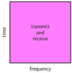
Full-duplex capability allows a transceiver to concurrently transmit and receive over the same frequency spectrum. In other words, transmission and reception can both make use of the full available frequency spectrum all the time. As mentioned, when operating in this full-duplex fashion, SI is inflicted onto a desired receive signal. To equip communication systems with full-duplex capability, engineers have developed a variety of ways to mitigate SI using radio frequency (RF) components, analog and digital filters, and other creative means. We will outline a variety of these strategies in this chapter. If SI can be sufficiently mitigated, a full-duplex transceiver can reliably receive while transmitting in-band, unlocking a number of enhancements, which we overview in the next section.
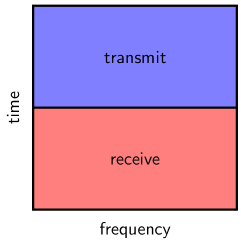
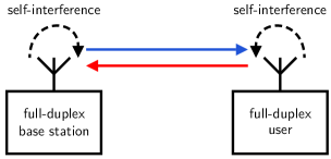
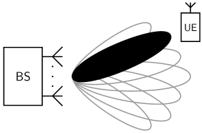
As depicted in Figure 2, a full-duplex base station may transmit and receive concurrently with a neighboring user that also has full-duplex capability. This makes better use of radio resources, and as intuition may suggest, leads to a potential doubling of spectral efficiency, as compared to half-duplex techniques. In other words, radio resources are being used twice as efficiently with full-duplex, since they are used for both transmission and reception, rather than divided as with FDD and TDD, as illustrated in Figure 1.
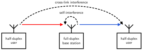
Figure 3 depicts another full-duplex operating mode, where a full-duplex base station transmits to a half-duplex user while receiving from another half-duplex user. This mode of operation can also potentially double spectral efficiency. It is important to note that cross-link interference is inflicted on the user receiving by the user transmitting, the level of which depends on a number of factors, chiefly the users’ locations and the environment.
Takeaways. Full-duplex operation is an exciting alternative to half-duplexing with FDD and TDD since it makes better use of radio resources. To enable full-duplex operation, however, self-interference must be mitigated sufficiently in order to reliably recover desired receive signals while transmitting in-band.
2 Enhancements Introduced by Full-Duplex
Compared to half-duplex operation, full-duplex can introduce enhancements to communication systems on a link level himal_fd_book_2020 ; ashu_inband_jsac_2014 ; kolodziej_techniques_2019 ; hong_sicapps_2014 , in medium access and spectrum sharing liao_protocol_2015 ; liao_cognitive_2014 ; liao_mag_2015 ; song_csma_2016 ; thilina_mag_2015 ; mishra_collision , and at the network level ozgur_isit_2017 ; gupta_fdiab —which we overview in this section.
2.1 Link-Level Analysis
The impacts of full-duplex can be readily observed by examining familiar link-level expressions foundational to wireless communication systems. To do so, consider the full-duplex operating mode depicted in Figure 3, where a full-duplex base station communicates with two half-duplex users. Taking the perspective of the full-duplex base station, we refer to its transmit link and receive link. The full-duplex capacity of the system, in the absence of interference, can be written as
| (1) |
where and are the maximum signal-to-noise ratios (SNRs) of the transmit and receive links, respectively. If employing TDD to duplex transmission and reception instead of full-duplex, the achievable sum spectral efficiency is
| (2) |
where is the fraction of time allocated to transmission, with the remainder allocated to reception. If employing FDD, this achievable sum spectral efficiency becomes
| (3) |
where is the fraction of the total bandwidth allocated to transmission, with the remainder allocated to reception. Here, since the integrated noise power is proportional to bandwidth, FDD enjoys SNR increases inversely proportional to bandwidth. The expression of as presented implicitly assumes an instantaneous transmit power constraint. Under an average transmit power constraint, which is less practical, and coincide heath_lozano .
Under full-duplex operation, the signal-to-interference-plus-noise ratio (SINR) of a desired receive signal (i.e., a signal-of-interest) on a given link is
| (4) |
where is the power of the desired receive signal; is the noise power; and is the power of interference (i.e., SI on the receive link, cross-link interference on the transmit link). The right-hand side of (4) can be obtained by dividing the numerator and denominator by the noise power , where is the SNR of the desired receive signal and is the interference-to-noise ratio (INR). The power of SI—and hence on the receive link—depends on the quality of SI mitigation employed at the full-duplex transceiver. For now, we can consider the degree of (residual) SI as being some level below the transmit power at the full-duplex transceiver. For instance, suppose our full-duplex base station is capable of reducing SI to a power level of
| (5) |
where is the total amount of mitigation (i.e., cancellation) achieved by its full-duplex solution. The total amount of SI mitigation may capture a variety of efforts, including antenna isolation and/or additional SI cancellation filtering, which we will discuss further in the next section. Since the power of a desired receive signal can be quite close to the noise floor in practical systems, SI power must be near or below the noise floor to ensure it does not prohibitively erode full-duplex resource gains. This means is not uncommon for to be on the order of dB for practical systems. Consider a transmit power of dBm and a noise floor of dBm: dB is required for (i.e., dB). Achieving this degree of mitigation is precisely what has hindered the adoption of full-duplex since the advent of wireless communications and what has made successful demonstrations of full-duplex so impressive cbc_mag_2015 ; duarte_experiment_2012 ; stanford_practical ; stanford_full_duplex_radios ; korpi_dissertation .
A summary of key power ratios of the full-duplex system in Figure 3.
-
Strength of the desired signal on the transmit link.
-
Strength of the desired signal on the receive link.
-
Strength of cross-link interference on the transmit link.
-
Strength of SI on the receive link.
-
Effective quality of the desired signal on the transmit link.
-
Effective quality of the desired signal on the receive link.
When full-duplexing transmission and reception, the maximum achievable spectral efficiency when treating residual interference as noise can be expressed as
| (6) |
When and , then . These expressions illustrate the potential resource gains offered by full-duplex compared to FDD and TDD, since there are no pre-log fractions; the effectiveness of such depends heavily on the presence of low SI and low cross-link interference, however.
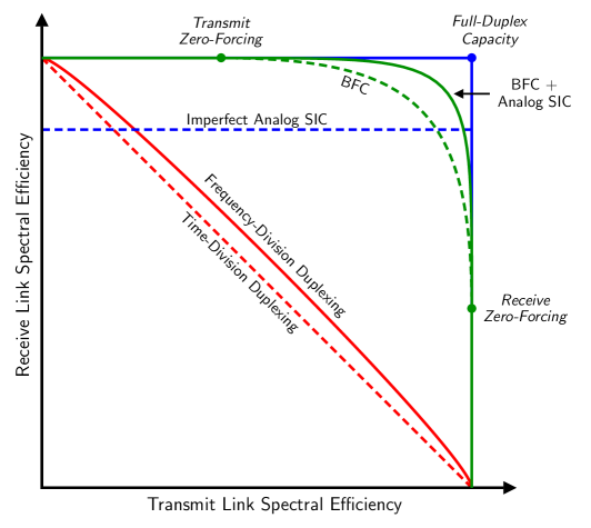
In Figure 4, we compare full-duplex operation against half-duplex operation with FDD and TDD by plotting their rate regions for various levels of SI and cross-link interference, where dB. Here, each line depicts the boundary of its rate region, encompassing all feasible transmit-receive spectral efficiency pairs , and each star () indicates the point that maximizes the sum spectral efficiency. The simple time-sharing nature of TDD is shown as the diagonal line connecting the two points of greedy time-sharing. FDD offers improvements over TDD, courtesy of its SNR gains when shrinking bandwidth, as mentioned. When SI power is mitigated to a level equal to the noise power (i.e., dB) and cross-link interference is also at the noise floor, the sum spectral efficiency can clearly exceed FDD and TDD, but only marginally. As SI and cross-link interference are reduced to below the noise floor, however, the achievable rate region of full-duplex expands, approaching that of its capacity region.
At lower SNRs, lower INRs are required for appreciable full-duplex operation, since the effects of interference magnify due to the steep nature of at low , tightening the requirements SI and cross-link interference mitigation. In addition, the SNR gains introduced by FDD are magnified since doubling nearly doubles at low , reducing the gap between FDD and the full-duplex capacity.
At higher SNRs, the gap between full-duplex and half-duplex grows, and the effects of interference diminish due to the saturating nature of at high . Higher INRs can be tolerated at high SNRs, relaxing the requirements on mitigating SI and cross-link interference.
2.2 In Medium Access and Spectrum Sharing
Half-duplex transceivers have been ubiquitous in wireless networks, and for good reason, communication standards and practices have been built on this half-duplex assumption. The ability to transmit and receive simultaneously and in-band is a transformative technology that can unlock new approaches to medium access and spectrum sharing that are more efficient than those built on a half-duplex assumption. In turn, full-duplex can facilitate wireless networks that deliver higher throughput, inflict lower interference, and make better use of spectrum.

Overcoming the Hidden Node Problem. To illustrate this, consider the famous hidden node problem in wireless networks: if two users are distant from one another but both within earshot of a nearby access point, the two users may be unaware when the other is transmitting to the access point. This can lead to collisions at the access point—and hence a waste of radio resources—if not dealt with. Conventional approaches to overcome this use handshaking between users and the access point to grant a user permission to transmit (e.g., request-to-send (RTS) and clear-to-send (CTS) mechanisms) along with random backoffs. By upgrading the access point with full-duplex capability, more efficient approaches to medium access can be employed liao_protocol_2015 ; song_csma_2016 ; thilina_mag_2015 . For instance, as illustrated in Figure 5, the full-duplex access point can broadcast a busy tone anytime it is receiving from a user. This busy tone can be heard by all users in the network, informing them to not transmit. Compared to conventional approaches to medium access, this approach consumes no additional radio resources and avoids the overhead associated with handshaking between users and the access point and reduces latency.
Dynamic Spectrum Access and Cognitive Radios. The number of devices with wireless connectivity has grown profoundly over the past two decades and will seemingly continue for years to come. The amount of available spectrum has not grown at a comparable pace, however. In light of this, researchers have proposed spectrum sharing and cognitive radios to dynamically and opportunistically make better use of frequency spectrum when it is free haykin_cognitive_2005 . For instance, a cognitive radio may sense a frequency band to see if it is being used by nearby devices. If there appears to be no activity, the cognitive radio may begin transmitting information. Periodically, the cognitive radio may halt transmission to sense the channel to ensure that it does not inflict interference on incumbents that have rights to the band—a waste of resources if none are detected. Full-duplex can make this process more efficient by empowering the cognitive radio to continuously sense the channel while transmitting liao_cognitive_2014 ; liao_mag_2015 ; thilina_mag_2015 . This allows it to more efficiently transmit information, since it does not have to halt transmission to sense the channel, and enables the cognitive radio to react more quickly to the presence of incumbents. Without full-duplex capability, the cognitive radio would presumably be unaware of the presence of incumbents until the end of its transmission, potentially causing interference that leads to collisions. Techniques discussed for overcoming the hidden node problem can be applied in this setting, as well, to instruct nearby cognitive radios to not transmit.
Channel Sensing to Reduce the Effects of Interference. As a final example of full-duplex applied to medium access, we consider the case where an access point serves users in the presence of neighboring nodes that may inflict interference, as explored in mishra_collision . For instance, one can consider two Wi-Fi access points operating independently but near one another. When one access point transmits to a user, successful reception at that user may be corrupted by neighboring interference, requiring the access point to retransmit the data. Naturally, this consumes radio resources and can lead to delays in communication. With full-duplex capability, the access point may sense the channel while transmitting, allowing it to potentially halt transmission to avoid collisions caused by neighboring interference and subsequently redirect resources to another user that may not be impacted by this interference mishra_collision ; thilina_mag_2015 . It is important to note that the requirements on mitigating SI are stricter when decoding data carried by a desired receive signal, compared to those for channel sensing, which is often merely detecting energy levels in a particular frequency band.

2.3 Network-Level Enhancements
Upgrading transceivers with full-duplex capability can be felt at the network level in a few ways. Even when only some devices are equipped with full-duplex—while the remainder are half-duplex-capable—a wireless network can enjoy improvements in throughput and latency gupta_fdiab ; ozgur_isit_2017 . In fact, network throughput can magnify beyond the doubling of spectral efficiency we are familiar with at the link level with full-duplex gupta_fdiab ; ozgur_isit_2017 . This can be attributed to the fact that full-duplex can reduce multiplexing delays, reduce overhead associated with medium access control, and enable new ways to manage interference—all of which can improve network throughput. We elaborate more on network-level enhancements of full-duplex in Subsection 4.6.
Other applications. There are applications of full-duplex technology beyond what was highlighted herein, such as in joint communication and sensing jcas_wcm_2021 ; xiao_jsac_2022 , secure communications wang_coml_2022 , military communications zheng_jamming_2013 ; riihonen_tactical_2017 , radar jcas_wcm_2021 , and more himal_fd_book_2020 ; hong_sicapps_2014 .
3 Self-Interference Cancellation
Successfully equipping a device with full-duplex capability relies on mitigating—or cancelling—SI to levels that are sufficiently low kolodziej_techniques_2019 . The amount of self-interference cancellation (SIC) needed depends on the particular application. In most settings, full-duplex solutions aim to cancel SI to near or below the receiver noise floor (i.e., roughly dB). This ensures that the full-duplex resource gains are not eroded by the presence of high SI, as highlighted in Figure 4. The residual SI is that which remains after efforts of SIC. In this section, we outline methods of SIC in both the analog and digital domains. Regardless of domain, the motivation behind SIC can largely be summarized as leveraging the fact that a transceiver has knowledge of its own transmitted signal and can therefore potentially reconstruct SI and subtract it from the received signal, leaving the desired portion virtually free of SI. In many cases, a staged approach to SIC is employed as illustrated in Figure 7, where a portion of SI is cancelled using an analog filter and a significant portion of the remainder is cancelled using digital filtering. This staged approach is depicted in Figure 8, where a full-duplex transceiver with separate antennas for transmission and reception employs an analog SIC filter between its antennas at RF and a digital SIC filter.

3.1 Analog Self-Interference Cancellation
As illustrated in Figure 8, analog SIC typically exists as a digitally-controlled analog filter placed between the transmitter and receiver of a full-duplex transceiver. Analog SIC filters come in many forms, existing as RF, intermediate frequency, and baseband circuitry, and even as optical filters kolodziej_techniques_2019 ; stanford_full_duplex_radios ; suarez_optical_2009 ; han_optical_2017 ; su_optical_2020 . Analog SIC is often driven by the tapping off a small portion of the upconverted RF transmit signal. This transmit signal undergoes filtering within the analog SIC filter before being injected at the receiver. The injected signal is an inverted reconstruction of SI, which, when combined with the received signal, destructively combines with SI. After this combining, there is some degree of residual SI due to imperfect reconstruction, which may stem from estimation errors, hardware limitations, and hardware imperfections. By tapping off the transmit signal after the transmit chain, analog SIC will inherently incorporate transmit-side impairments unbeknownst to baseband, such as power amplifier (PA) nonlinearities, which have proven to be a dominant factor in SIC korpi_full-duplex_2014 ; korpi_dissertation . Other approaches, sometimes called digitally-assisted approaches, use a dedicated transmit chain to drive analog SIC, as opposed to tapping off the transmit signal directly kolodziej_techniques_2019 . This approach cannot as well capture transmit-side impairments present in SI, however, since this second transmit chain naturally will not contain all artifacts of the true transmit chain.

Configuring an Analog Self-Interference Cancellation Filter. Tuning an analog SIC filter to effectively cancel SI largely consists of measuring SI and then configuring the filter to reconstruct its inverse. Analog SIC can be implemented as a time-domain filter or as a frequency-domain filter, meaning particular methods may vary but all tackle the same goal of reconstructing SI kolodziej_techniques_2019 . One method of time-domain analog SIC is to estimate the impulse response of the SI channel and then configure the analog filter to produce this (inverted) impulse response estimate, effectively equalizing SI. Estimation of the SI channel is typically executed by transmitting a pilot signal during a quiet period, when no desired receive signal is present. One difficulty with practically executing this method lay in the fact that estimation of the SI channel takes place digitally, meaning estimation of the channel of interest for analog SIC may be complicated by artifacts of the transmit and receive chains before and after analog SIC. This can be further complicated by the fact that an analog filter may not have an ideal impulse response itself, making it difficult to reliably produce the desired impulse response.
As an attempt to overcome these challenges, another approach is to measure SI and then measure the impulse response of the analog filter. Then, the filter can be configured to produce an inverted reconstruction of SI. For instance, consider a column vector of measured SI time-domain samples (during a quiet period) and a matrix whose -th column is the measured impulse response of the -th tap of the filter. Analog finite impulse response (FIR) filter weights can be computed to minimize the error in reconstructing an inverted copy of the measured SI as
| (7) |
which has the well-known closed form solution . This approach has shown to be fairly robust, since it accounts for the imperfect impulse response of each of the filter’s taps.

While it may seem fairly straightforward to implement analog SIC, it is practically quite challenging in most cases, especially outside of well-controlled lab settings. Most notably, there is small margin for error in SIC due to the overwhelming strength of SI, reinforcing the need for extremely accurate, adaptable, and low-overhead SI reconstruction. Another challenging aspect is the need to miniaturize analog SIC filters into form-factors that integrate into devices such as cell phones, laptops, wireless routers, base stations, and the like kolodziej_techniques_2019 . Miniaturization is especially challenging in settings where the delay spread of SI has the potential to be high, since propagation delays need to be physically realized within the analog SIC filter.
3.2 Digital Self-Interference Cancellation
Cancelling SI through digital signal processing is naturally an attractive option in addition to analog SIC. The flexibility and sophistication of digital filtering can be applied to estimate and cancel SI and has had impressive success korpi_full-duplex_2014 ; korpi_widely_2014 ; korpi_dissertation . As depicted in Figure 7 and Figure 8, digital SIC is executed after analog SIC and therefore aims to cancel residual SI that remains after prior efforts of cancellation. Naturally, one may ask whether digital SIC can cancel all SI, rendering analog SIC unnecessary. In general, this is not possible for a few reasons, stemming from hardware limitations and nonidealities.
Limited Dynamic Range of Analog-to-Digital Converters. With reasonable resolution and appropriate gain control before analog-to-digital conversion, quantization noise is rarely an issue in traditional half-duplex systems. In full-duplex systems, on the other hand, the strength of SI has the potential to saturate analog-to-digital converters (ADCs), even with ideal automatic gain control (AGC) and a reasonable number of bits korpi_full-duplex_2014 ; ashu_inband_jsac_2014 . Since AGC acts on the combination of a desired signal plus SI and noise at the ADC input, the strength of quantization noise is dictated largely by that of SI. In such cases, only a portion of the ADC’s total dynamic range is effectively used to quantize a desired signal. Consequently, even if SI could be completely reconstructed and cancelled digitally, its effects may remain in the form of increased quantization noise, which can severely and irreversibly degrade the quality of a desired receive signal. This reinforces the need to sufficiently cancel SI before it reaches the ADC input, which is often most reliably done via analog SIC.
Transceiver Nonidealities. Practical transceivers introduce nonidealities in the transmit and receive chains, such as amplifier nonlinearities, I/Q imbalance, transmitter thermal noise, and phase noise, which complicate digital SIC since the digital domain does not have knowledge of these imperfections korpi_dissertation . When these nonidealities are not negligible, this requires digital SIC to accurately estimate and subsequently cancel them, which can be computationally complex. To reduce this burden, analog SIC can be well positioned to cancel transmit-side impairments using the RF transmit signal as input to its cancellation filter, which inherently will include nonidealities introduced by transmit PAs and transmit thermal noise, for example. In addition, analog SIC can importantly ensure that the power of residual SI is sufficiently low such that it does not overwhelm and saturate receive-chain components such as low noise amplifiers (LNAs), which practically have a limited dynamic range that can be exceeded by SI korpi_full-duplex_2014 .
Recent Breakthroughs using Machine Learning. In addition to classical signal processing approaches for digital SIC, solutions based on machine learning have been gaining traction and have shown impressive results stimming_implement_2018 ; guo_realtime_2018 ; stimming_nn_2018 ; stimming_implement_2020 ; guo_dsic_2019 ; mishra_mimo_2020 ; stimming_joint_2021 . The main motivation for the use of machine learning over classical approaches for digital SIC is to capture transceiver nonidealities with reduced complexity. Classical signal processing approaches have been able to effectively estimate and account for transceiver impairments when reconstructing and subsequently cancelling SI. This is done by modeling transceiver impairments with established, parameterized models, but the estimation of model parameters is computationally expensive with classical methods. Machine learning has shown to be able to offer comparable performance as classical methods in capturing transceiver impairments when reconstructing SI but with reduced complexity. Experimental validation of these digital SIC solutions based on machine learning has proven their effectiveness stimming_implement_2018 ; guo_realtime_2018 ; stimming_implement_2020 . In addition, machine learning can be used to reduce the complexity of SIC in multi-antenna systems. Rather than merely replicating single-antenna SIC solutions as an extension to multi-antenna systems, researchers have shown that machine learning can reduce the size and complexity of digital SIC by learning correlations between antennas mishra_mimo_2020 .
3.3 Circulators and Antenna Isolation
An RF component known as a circulator has been used in many monostatic radar and communication applications as a duplexer when a single antenna is used for simultaneous transmission and reception of RF signals kolodziej_techniques_2019 ; ashu_inband_jsac_2014 . In its simplest form, a circulator is a three-port, passive device where a signal entering a given port is “circulated” to the next port in the rotation. An example of this device being used with a single antenna shared by transmission and reception can be seen in Figure 10. Transmit signals enter Port 1 of the circulator and exit at Port 2, where they are radiated by the antenna. Signals received by the antenna enter Port 2 and are circulated to Port 3, where they exit the circulator and enter the receive chain. This establishes isolation between the transmitter and receiver of a full-duplex device using a single antenna for transmission and reception.
One may reason that with an ideal circulator and with two radios operating in free space, full-duplex operation is trivial since perfect isolation is achieved between a radio’s transmit signal and a desired receive signal. In reality, a circulator effectively offers limited RF isolation between its ports, which introduces SI at the receiver. This is due to a number of factors, most notably the leakage between ports, reflections caused by imperfect matching at the antenna, and reflections off the environment. Circulators with small form-factors that offer high isolation for full-duplex are an active area of research with immense potential laughlin_jsac_2014 ; dinc_2017 . Nonetheless, analog and digital SIC can be used in conjunction with a circulator for single-antenna full-duplex transceivers. In such cases, SIC aims to cancel circulator leakage, as well as reflections off the environment and from the antenna.

Takeaways. Digital SIC is an effective and flexible route to enabling full-duplex, but it is bottlenecked in practice by imperfections and limitations of hardware. As such, it is often used in conjunction with analog SIC, which can inherently account for hardware impairments, relax the requirements of digital SIC, and prevent SI from saturating receive-chain components. Circulators and other duplexers can provide isolation between the transmitter and receiver of a full-duplex transceiver when using a single antenna, effectively weakening SI that analog and digital SIC must tackle.
4 A New Frontier: Full-Duplex Millimeter-Wave Systems
To meet the ever-growing demand for high-rate wireless access, cellular networks have turned to mmWave carrier frequencies, typically classified as ranging from around GHz to GHz jeff_5g_2014 . Fifth-generation (5G) cellular networks and IEEE 802.11ad/ay, for instance, leverage frequency bands that span hundreds of megahertz. These wide swaths of spectrum facilitate higher data rates and enable new applications in entertainment, industry, and sensing. The widespread deployment of mmWave networks has faced hurdles thus far, but it is expected they will see greater success through the end of the 2020s. Both mmWave communication systems and full-duplex technology were explored concurrently during the 2010s and were proposed as core technologies for next-generation wireless networks. The combination of the two—full-duplex mmWave communication systems—has not been explored as extensively. Only recently has this topic garnered noteworthy attention from industry and academia roberts_wcm ; xia_2017 ; liu_beamforming_2016 ; 3GPP_IAB_2 .
4.1 Prelude: Full-Duplex MIMO Transceivers
With multiple antennas at a transmitter and a receiver, there is the potential to multiplex more than one data stream over the resulting multiple-input multiple-output (MIMO) wireless channel via spatial signal processing heath_lozano . MIMO communication transformed wireless networks forever by offering multiplicative rate gains over traditional single-input single-output communication systems. Given their prominence, the extension of full-duplex to MIMO transceivers was imperative. With multiple antennas at the transmitter and receiver of a full-duplex transceiver, SI is inflicted onto each receive antenna by each transmit antenna, leading to a MIMO SI channel. There is a quite natural extension of analog and digital SI to full-duplex MIMO transceivers korpi_dissertation ; stanford_mimo_2014 ; Huberman_Le-Ngoc_2015 . Perhaps more exciting, though, is the potential to mitigate SI through precoding and combining (i.e., spatial processing) at the transmitter and receiver of the full-duplex transceiver riihonen_loopback ; himal_fdrelay_2014 ; ngo_jsac_2014 ; Day_Margetts_Bliss_Schniter_2012 . By strategically transmitting energy into the SI channel and receiving energy from it, SI can be mitigated spatially while still communicating desired signals in a MIMO fashion. As the number of antennas grows—and especially in the massive MIMO regime—the prospects of spatial cancellation are even more promising. There is extensive literature on the subject of full-duplex MIMO systems; we encourage interested readers to explore stanford_mimo_2014 ; Huberman_Le-Ngoc_2015 ; riihonen_loopback ; himal_fdrelay_2014 ; ngo_jsac_2014 ; Day_Margetts_Bliss_Schniter_2012 ; everett_softnull_2016 and references therein for more details. In the remainder of this section, we consider a particular class of full-duplex MIMO transceivers: those at mmWave frequencies. Solutions for full-duplex mmWave systems draw inspiration from those for traditional full-duplex MIMO systems at sub-6 GHz but face unique challenges and are subject to new transceiver- and network-level factors.
4.2 What’s New at Millimeter-Wave Frequencies?
Communication at mmWave is more than a mere shift in carrier frequency, as elegantly stated in heath_overview_2016 . In general, path loss increases with carrier frequency, which necessitates the use of dense antenna arrays to supply high beamforming gains that can deliver link margins that sustain high-rate communication. Antenna arrays on mmWave network infrastructure are typically equipped with - antennas, whereas user equipment may be equipped with - elements. Fortunately, antenna footprint shrinks as carrier frequency increases, allowing dense antenna arrays to fit in convenient form-factors. The severe path loss and susceptibility to blockage at mmWave frequencies, coupled with highly directional beamforming, reduces inter-user interference and facilitates base station deployments much denser than traditional sub-6 GHz macrocell deployments. All of this has led to new transceiver-level and network-level challenges and solutions at mmWave.
4.3 Exciting Potential to Tackle Self-Interference via Beamforming
In Subsection 4.1, we mentioned that a multi-antenna full-duplex system can design its transmit precoder and receive combiner to reduce SI coupled over the MIMO SI channel. At mmWave, the prospect of such spatial SIC notably improves for a few reasons xia_2017 ; liu_beamforming_2016 ; roberts_wcm . First of all, path loss and blockage increases at mmWave frequencies, compared to sub-6 GHz frequencies, which presumably weakens SI as it couples from a transmitter to receiver, both directly over-the-air and due to reflections off the environment; reflectivity increases at mmWave, however, which may lead to more SI from the environment. Second, with denser antenna arrays, the degrees-of-freedom available to cancel SI increases, compared to traditional sub-6 GHz MIMO systems, which typically only have - antennas. It is important to note that, as the number of antennas has increased immensely at mmWave, the number of data streams communicated has remained of similar order. Hybrid analog/digital beamforming and analog-only beamforming architectures, which are ubiquitous thus far in mmWave communication systems, fundamentally limit the number of data streams to the number of digital-to-analog converters (DACs) and ADCs, which is comparable to that in conventional sub-6 GHz MIMO systems. With one or few data streams communicated and tens or hundreds of antennas, many degrees-of-freedom are potentially available for cancelling SI via strategic design of transmit and receive beamformers at a full-duplex mmWave transceiver.
Excitedly, if beamforming can cancel SI sufficiently, the need for analog and/or digital SIC vanishes, meaning there is the potential for full-duplex mmWave systems to operate without any additional hardware or complex signal processing. In other words, analog and digital SIC may be needed for full-duplex mmWave systems with sufficient spatial SIC. Plenty of existing work has highlighted this by designing transmit and receive beamformers in such a way that SI is mitigated while maintaining downlink and uplink to users roberts_wcm ; riihonen_loopback ; everett_softnull_2016 ; xia_2017 ; liu_beamforming_2016 ; roberts_2021_robustcb ; lopez-valcarce_beamformer_2019 ; lopez_prelcic_2019_analog ; prelcic_2019_hybrid ; satyanarayana_hybrid_2019 ; zhu_uav_joint_2020 ; da_silva_2020 ; lopez_analog_2022 ; koc_ojcoms_2021 ; cai_robust_2019 ; roberts_bflrdr ; roberts_equipping_2020 . Interestingly, unlike traditional analog and digital SIC solutions, transmit beamforming introduces the unique opportunity to reduce the degree of SI that ever reaches the receive antennas. Like analog SIC, transmit and receive beamforming can be used to prevent SI from saturating receive chain components. For instance, in roberts_bflrdr , a hybrid beamforming design is presented that guarantees SI is below some power level at each LNA and each ADC at the receiver of the full-duplex mmWave device, ensuring they do not saturate. In addition to using beamforming alone to mitigate SI, researchers have also considered analog and/or digital SIC in conjunction, which relaxes the cancellation requirements of beamforming, allowing it to better serve uplink and downlink at the cost of added hardware or signal processing Huberman_Le-Ngoc_2015 ; roberts_equipping_2020 ; smida_asic ; Alexandropoulos_Duarte_2017 ; singh_2020_acm ; Zhang_Luo_2019 ; dinc_60_2016 ; suk_iab_2022 . The rate region boundaries with spatial cancellation via beamforming (sometimes termed beamforming cancellation) and analog SIC are shown in Figure 11 roberts_wcm .
4.4 Example Beamforming Design Problems
We now overview two sample spatial SIC design problems for full-duplex mmWave systems, with the goal of introducing readers to the design objectives and considerations surrounding such research problems and those taking a similar form.

Analog Beamforming Design. Consider the system illustrated in Figure 12. Suppose the full-duplex mmWave base station equipped with analog-only beamforming—as opposed to hybrid digital/analog beamforming heath_overview_2016 —is serving an uplink user and a downlink user simultaneously and in-band, both of which are single-antenna devices. It is currently practical to consider the use of separate, independently-controlled transmit and receive arrays at the base station equipped with and antennas, respectively roberts_wcm . Let and be the transmit and receive beamforming vectors used at the full-duplex base station. Let be the MIMO SI channel matrix manifesting between the transmit and receive arrays. Let be the channel vector from the base station to the downlink user. Let be the channel vector from the uplink user to the base station. The full-duplex base station will rely solely on beamforming to mitigate SI with no additional analog or digital SIC.
Practical analog beamforming networks are comprised of digitally-controlled phase shifters. In addition to phase control, some networks also offer quantized amplitude control through digitally-controlled attenuators or variable-gain amplifiers (VGAs) (see Subsection 4.5). Quantized phase and amplitude control confines all physically realizable analog beamformers to come from some discrete sets, which can be captured as simply and . The transmit link and receive link SNRs are functions of their beamformers and can be expressed as
| (8) |
where and are the transmit powers of the base station and the uplink user, while and are the noise powers of the base station and the downlink user. The SI and cross-link interference terms of the system are
| (9) |
where is a function of the transmit and receive beams at the full-duplex base station and is solely a function of the cross-link channel from the uplink user to the downlink user. Together, these desired and interference terms form the SINRs of the two links as
| (10) |
which determine the achievable spectral efficiencies as
| (11) |
when treating interference as noise. Notice that the transmit link quality and therefore its spectral efficiency are solely functions of the transmit beam . The fate of the receive link, however, is determined by both and due to SI. It would desirable to design and such that they deliver high SNRs and couple low SI.
This motivates the following analog beamforming design problem, which aims to maximize the sum spectral efficiency of the system, while requiring the transmit and receive beams to be physically realizable.
| (12a) | ||||
| (12b) | ||||
Several existing works on mmWave full-duplex aim to solve this problem or one of similar form lopez_analog_2021 ; lopez_analog_2022 ; da_silva_2020 . In general, this problem is difficult to solve due to the non-convexity of the objective from the coupling of and and the fact that and are non-convex sets. Researchers typically instead tackle problems that are more readily solved and still yield high sum spectral efficiency.
One practical issue with solving analog beamforming problems of this type is that they are executed for each user pair, which can consume prohibitive amounts of radio resources (e.g., for channel estimation and over-the-air feedback) and computational resources. In fact, the time required to solve these sorts of problems may not translate to timescales of practical systems, even with modern computing power. Moreover, many existing solutions rely on unrealistic assumptions, such as real-time downlink/uplink MIMO channel knowledge (i.e., and ), which is not obtainable in practical mmWave systems today.
Analog Beamforming Codebook Design. In the previous example, we considered the problem of designing transmit and receive beams that maximize sum spectral efficiency. Now, to circumvent and overcome some of the practical challenges mentioned in the previous example, let us consider the goal of designing transmit and receive codebooks that maximize sum spectral efficiency in full-duplex mmWave systems. Let us build on the previous example and the notation used therein. Suppose it is required that the transmit beam be selected from some set of transmit beams , called a transmit codebook, which is common in practical systems. Likewise, suppose it is required that the receive beam be selected from some codebook of receive beams . Here, and are on the order of tens or hundreds at most, meaning it is realistically the case that and .
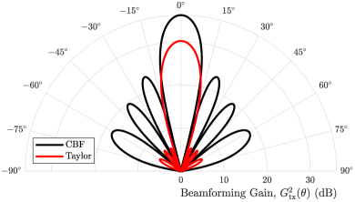
It is fairly straightforward to design transmit and receive codebooks for traditional half-duplex mmWave systems, typically done by tessellating beams to cover a desired service region to ensure that a user falling in this region can be served with high gain with at least one beam from the codebook (e.g., see Figure 14). The design of codebooks for full-duplex mmWave systems, on the other hand, is far more involved and has only been investigated in roberts_lonestar ; roberts_2021_robustcb thus far. Consider the following design problem, which aims to design codebook matrices and that maximize the expected sum spectral efficiency across a known user distribution for a given , for instance.
| (13a) | ||||
| (13b) | ||||
| (13c) | ||||
| (13d) | ||||
Here, these codebook matrices are structured such that the -th column of is and the -th column of is , both of which are required to be physically realizable beamforming vectors, hence (13c) and (13d). To serve each user pair, some transmit and receive beams and are selected from their respective codebooks. With random user placement, any transmit and receive beam may be chosen from the codebooks, meaning desirable codebooks and would offer low for all possible and while still capable of delivering high beamforming gains. This is a difficult problem to solve, largely due to the daunting objective of aiming to maximize average sum spectral efficiency, but provides good direction for desirable codebooks and .
In roberts_lonestar ; roberts_2021_robustcb , a similar problem is tackled, as shown below in problem (14). Here, the objective is instead to minimize average SI coupled between possible transmit and receive beams across the channel , effectively minimizing average . In doing so, high beamforming gain and broad coverage over some transmit and receive coverage regions are enforced by (14b) and (14c), where and are design parameters that throttle the so-called coverage variance of each codebook. In essence, these constraints ensure codebooks can reliably deliver high and high , while the objective aims to minimize .
| (14a) | ||||
| (14b) | ||||
| (14c) | ||||
| (14d) | ||||
| (14e) | ||||
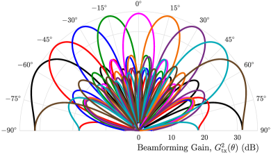
A codebook of beams output by this design is shown in Figure 13. Compared to traditional beams, the beams produced by roberts_lonestar ; roberts_2021_robustcb make use of side lobes to cancel SI spatially while providing adequate coverage across the service region from to . The codebooks designed with this framework proved to offer far greater robustness to SI and similar beamforming gain when compared to conventional codebooks, which allowed them to deliver sum spectral efficiencies that approach the full-duplex capacity without analog or digital SIC. Designs like this are particularly exciting because they have the potential to accommodate codebook-based beam alignment while also mitigating SI through beamforming. For more details and more extensive evaluation of this design, please see roberts_lonestar ; roberts_2021_robustcb .
4.5 Key Practical Challenges and Considerations
We now outline important considerations when designing solutions for practical full-duplex mmWave systems, some of which have already been touched on in this chapter.
Digitally-Controlled Analog Beamforming Networks. Unlike digital beamforming, which takes place in software/logic, analog beamforming is executed using phase shifter components, potentially along with attenuators and/or amplifiers, all of which are digitally-controlled. In other words, some finite number of bits are dedicated to realizing the phase and amplitude of each beamforming weight. For instance, the discrete set of physically realizable phase settings by phase shifters with settings uniformly distributed between and with resolution bits can be expressed as
| (15) |
meaning it is practically required, for the -th beamforming weight , that for all . In practice, it should be noted that both phase and amplitude control typically have some error associated with them, which is generally frequency-dependent.
Some phased arrays employ phase shifters based on a vector modulator architecture, where the in-phase and quadrature components of a signal can be scaled independently to produce a desired phase shift, in which case phase shifter settings are presumably no longer uniformly spaced. Note that such an architecture also offers a means to scale the amplitude of the output signal. Practical beamforming-based full-duplex solutions for mmWave systems should account for the limitations imposed by a particular analog beamforming architecture. Quantized control of each beamforming weight leads to non-convex sets that are difficult to optimize over. Blindly projecting a solution onto the set of physically realizable beamforming vectors can be detrimental, as small errors in this full-duplex setting are magnified by the sheer strength of SI relative to a desired signal. This motivates the use of high-resolution phase shifters in full-duplex mmWave systems and/or ways to handle the non-convexity posed by quantized phase shifters.
Accommodating Codebook-Based Beam Alignment. Codebook-based analog beamforming is a critical component of mmWave communication systems heath_overview_2016 ; ethan_beam . Rather than measure a high-dimensional MIMO channel and subsequently configure an analog beamforming network, modern mmWave systems instead rely on beam alignment procedures to identify promising beamforming directions, typically via exploration of a codebook of candidate beams heath_overview_2016 ; ethan_beam ; junyi_wang_beam_2009 . This offers a simple and robust way to configure an analog beamforming network without downlink/uplink MIMO channel knowledge a priori, which is not obtainable in practice.
Let and be transmit and receive beamforming codebooks used at a full-duplex device. Executing beam alignment on each link independently (in a half-duplex fashion) would aim to solve (or approximately solve) the following problems or ones taking a similar form.
| (16) |
If selecting the transmit and receive beams independently to maximize each link’s SNR, the selected beam pair may couple high SI when using traditional beamforming codebooks. In other words, may be much greater than dB. In fact, we show this has been confirmed by recent measurements roberts_att_angular , which we cover shortly in Subsection 4.7. Therefore, one can imagine it would be preferable from a full-duplex perspective to jointly select transmit and receive beams that deliver high and and also couple low . This is precisely the motivation for roberts_steer , which is also introduced in Subsection 4.7. If codebooks could be designed such that all possible couple sufficiently low SI, then beam alignment may be conducted on the transmit and receive links independently, as shown in (16), with guarantees of low SI regardless of which beams are selected—the motivation for roberts_lonestar ; roberts_2021_robustcb and the codebook design problem introduced in Subsection 4.3. Creating solutions like these that accommodate beam alignment will be critical to the deployment of full-duplex mmWave systems.
Self-Interference Channel Estimation and Limited Channel Knowledge. As mentioned just previously, current practical mmWave systems circumvent downlink/uplink channel estimation via beam alignment, meaning they do not have knowledge of the transmit and receive MIMO channels and . Practical beamforming-based solutions for full-duplex mmWave systems should account for this. Efficient and accurate estimation of the SI MIMO channel is a research problem still in its infancy. This is perhaps most largely due to the fact that modeling is still an open research problem itself, whose outcomes may inspire strategies for its estimation. MIMO channel estimation in mmWave transceivers is complicated by the sheer size of these channels and the fact that DACs and ADCs observe the channel through the lens of analog beamformers heath_overview_2016 . Routes to reduce estimation overhead would be valuable contributions, potentially by leveraging static portions of the SI channel (e.g., the direct coupling between the arrays) and/or by accurate channel modeling. Nonetheless, whatever SI channel estimation strategies are developed will naturally be imperfect to some degree, suggesting that practical designs should be robust to channel estimation error. Robustness is especially critical in full-duplex settings, since small errors in mitigating SI can be detrimental due to its overwhelming strength.
Leveraging User Selection. A full-duplex mmWave base station will likely serve multiple downlink users and uplink users over many time slots. As assumed thus far, let us consider the case where the base station can serve a single downlink-uplink user pair in a full-duplex fashion at any given time, multiplexing user pairs in time. The degree of SI coupled at the full-duplex base station depends on the transmit and receive beams when serving a particular downlink-uplink user pair. In addition, the degree of cross-link interference depends on the two users being served. When given a pool of user pairs needing service, one can therefore imagine that strategically selecting which user pair to serve has the potential to be a powerful tool to improve full-duplex performance roberts_wcm . This concept has not been fully fleshed out in existing literature and deserves future study. Interesting future work, for instance, would be the design of intelligent schedulers that incorporate full-duplex user selection to improve link-level spectral efficiency and gains in network-level throughput.
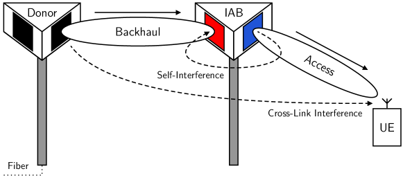
4.6 Full-Duplex Integrated Access and Backhaul
A particularly motivating application of full-duplex in mmWave cellular networks is in integrated access and backhaul (IAB)cudak21integrated ; iab ; 3GPP_IAB_2 , where a fiber-connected base station serves nearby users and is responsible for maintaining a wireless backhaul to one or more nearby base stations, as illustrated in Figure 15. By using the same pool of mmWave spectrum for access and wireless backhauling, dense mmWave networks can be deployed with fewer dedicated fiber connections, which reduces the cost, time, and permitting associated with deployment. Like other multi-hop wireless networks, however, IAB networks have faced scaling challenges due to degraded throughput and higher latency as the network grows. Recent work has investigated the use of full-duplex to overcome these obstacles gupta_fdiab ; suk_iab_2022 .

Inter-sector and intra-sector full-duplex. An IAB node can operate in a full-duplex fashion in two main ways, depending on scope. Consider a sectorized IAB node with three sectors, each equipped with a transceiver serving a field-of-view. The first potential full-duplex operating mode, which we refer to as inter-sector full-duplex, allows each sector to either transmit or receive, meaning SI may be inflicted by one sector onto one or both of the other sectors. Figure 15 depicts inter-sector full-duplex, for instance, where one sector receives while another transmits in-band. With inter-sector full-duplex, sectors are no longer required to collectively transmit or collectively receive but rather can be scheduled independently, and the transceiver on each sector can be merely half-duplex-capable. This full-duplex mode unlocks scheduling opportunities that are otherwise not available, allowing the network to achieve higher throughput, as we will highlight shortly.
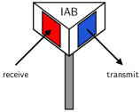
The other potential full-duplex operating mode we refer to as intra-sector full-duplex, where each sector is equipped with a full-duplex transceiver, and we illustrate in Figure 16. In this case, each sector may transmit and receive from a downlink-uplink user pair within its field-of-view. Notice that, when each sector operates simultaneously and in-band as its neighboring sectors, SI is inflicted from each transmitting sector onto each receiving sector. Naturally, intra-sector full-duplex has the potential to outperform inter-sector full-duplex, but the gains of such have not been thoroughly investigated. Early deployments of full-duplex mmWave base stations, especially for IAB, will likely be of the inter-sector form, since SI is likely less severe and half-duplex transceivers can be used per sector.
Recent Progress Validating Full-Duplex IAB. Full-duplex IAB networks are studied in gupta_fdiab to characterize the throughput and latency gains when upgrading IAB nodes from half-duplex to full-duplex transceivers. Note that, in gupta_fdiab , users were kept as half-duplex devices, which is a realistic assumption for the foreseeable future. The authors show through analysis and simulation that, with full-duplex IAB nodes, user latency can reduce four-fold and user throughput can improve eight-fold for fourth-hop users—far transcending the familiar doubling of spectral efficiency offered by full-duplex at the link level. In general, gupta_fdiab shows that users further from the donor enjoy greater performance improvements with full-duplex. This can be explained by the fact that full-duplex IAB networks can meet latency and throughput targets that half-duplex IAB networks cannot, yielding relative gains that can tend to infinity. Ultimately, the gains offered by full-duplex are thanks to the scheduling opportunities it unlocks: certain links that must be orthogonalized with half-duplex IAB nodes need not be with full-duplex, allowing packets to more quickly propagate through the multi-hop network. Compared to their half-duplex counterparts, full-duplex IAB networks can facilitate reduced latency, higher throughput, fairer service, and deeper networks—even with imperfect SIC gupta_fdiab .
t]
4.7 Recent Experimental Research Outcomes
The majority of research on full-duplex mmWave systems has been theoretical in nature, using simulation to validate proposed solutions. Recently, there has been work experimentally investigating full-duplex mmWave systems, two efforts of which we introduce herein.
t]
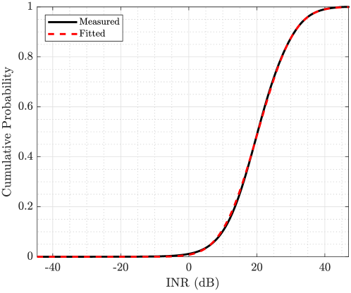
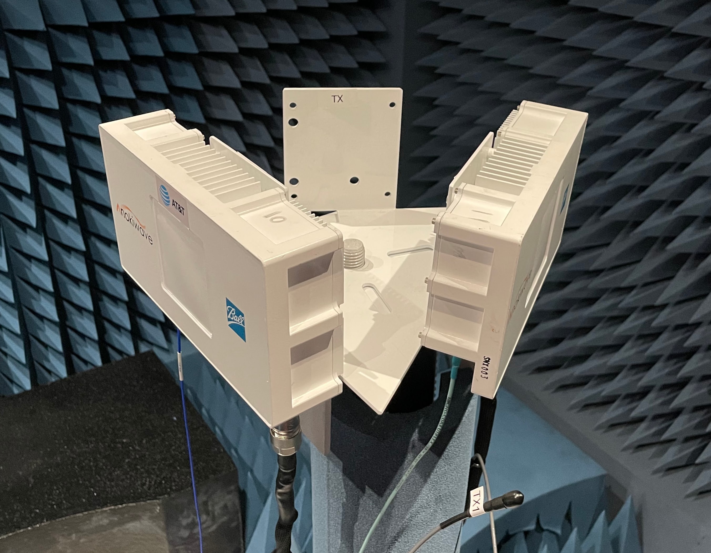
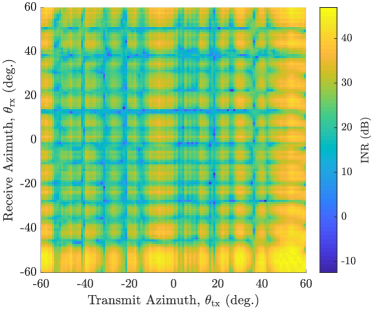
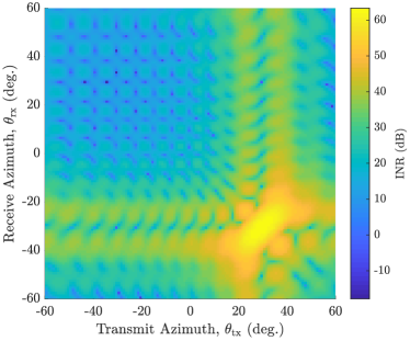
Measurements of mmWave Self-Interference. SI was studied quite extensively over the past decade or so, largely in the context of sub-6 GHz transceivers. To progress development of full-duplex mmWave systems, a necessary first step is to better understand SI in mmWave systems. Measurements of mmWave SI in suk_iab_2022 ; rajagopal_2014 ; kohda_2015 ; lee_2015 ; yang_2016 ; he_2017 ; haneda_2018 provide useful insights but do not offer a means to evaluate proposed mmWave full-duplex solutions since they provide neither a MIMO SI channel model nor adequate beam-based measurements; most of these were taken using horn or lens antennas, not phased ararys. To evaluate beamforming-based mmWave full-duplex solutions thus far, researchers have primarily used highly idealized channel models. To address these shortcomings, a measurement campaign of SI at 28 GHz was conducted in roberts_att_angular ; roberts_2021_att_measure using a multi-panel 1616-element phased array platform. In this campaign roberts_att_angular ; roberts_2021_att_measure , a spatial inspection of SI was conducted in an anechoic chamber by electronically sweeping the beams of the transmit phased array and receive phased array across a number of combinations in azimuth and elevation. For each transmit direction and receive direction, SI power was measured, for a total of nearly 6.5 million measurements. This work showed that SI indeed tends to be well above the noise floor—even with highly directional mmWave beams—but select transmit-receive beam pairs coupled levels of SI below the noise floor without any additional cancellation. These measurements revealed large-scale trends based on steering direction, along with noteworthy small-scale phenomena when beams undergo small shifts (on the order of one degree). The authors provide a statistical characterization of their measurements, allowing researchers to draw realistic realizations of SI and conduct statistical analyses. A key takeaway from this work showed that a commonly-used idealized near-field channel model (i.e., the spherical-wave channel model spherical_2005 ) is not a suitable one for practical mmWave full-duplex systems. This motivates the need for a new measurement-backed channel model for SI in full-duplex mmWave systems.
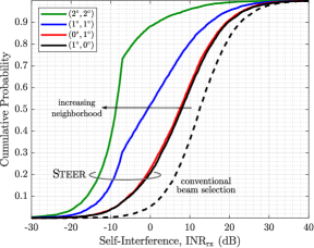
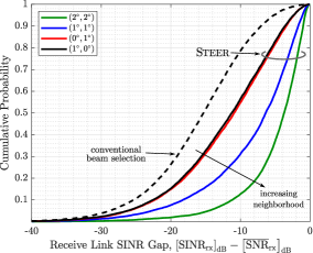
Beam Selection for Full-Duplex mmWave Communication Systems. A particularly exciting observation from the measurements in roberts_att_angular was that slightly shifting the transmit and/or receive beams at the full-duplex transceiver (on the order of one degree) could significantly reduce SI, often by dB or more. This motivated the work of roberts_steer , in which the authors propose the first beam selection methodology for full-duplex mmWave communication systems. Traditional beam selection typically selects beams that maximize SNR via codebook-based beam alignment measurements, as highlighted in (16). In roberts_steer , the authors propose a measurement-driven beam selection methodology, called Steer, atop conventional beam alignment that incorporates SI into transmit and receive beam selection at a full-duplex mmWave transceiver.
Suppose a full-duplex base station serves a downlink user and uplink user as illustrated in Figure 12. Taking the perspective of a full-duplex base station, let be a set (a codebook) of candidate transmit beam steering directions (azimuth-elevation pairs) used during beam alignment, and let be a codebook of candidate receive beam steering directions defined analogously (e.g., see Figure 14).
| (17) | ||||
| (18) |
Solving the following beam selection problems through conventional beam alignment yields initial beam selections at the full-duplex base station.
| (19) | ||||
| (20) |
While these initial beam selections may yield high SNRs, they are likely to couple high levels of SI, shown by measurements in roberts_att_angular . To identify transmit and receive beams that the base station can use to deliver high SNRs and low SI, the authors of roberts_steer propose Steer.
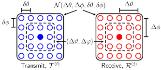
Steer leverages the small-scale variability observed in the measurements of roberts_att_angular to preserve high and high while reducing . To identify attractive steering directions for full-duplex operation, Steer measures the SI incurred when transmitting and receiving around the spatial neighborhoods surrounding the initial transmit and receive steering directions, as described by Figure 20. Quantifying the size of these spatial neighborhoods, let and be maximum absolute azimuthal and elevational deviations from the given transmit direction and receive direction. Discretizing these neighborhoods, let and be the measurement resolution in azimuth and elevation, respectively, which should not be larger than . For instance, while . The spatial neighborhood surrounding a transmit/receive direction can be expressed using the azimuthal neighborhood and elevational neighborhood defined as
| (21) | ||||
| (22) |
where is the floor operation and . The complete neighborhood is the product of the azimuthal and elevational neighborhoods as
| (23) |
The spatial neighborhoods and surrounding the transmit and receive directions output by conventional beam selection are respectively written as
| (24) | ||||
| (25) |
Let be the receive link INR due to SI when transmitting toward and receiving toward at the full-duplex base station. Steer solves the following beam selection problem to net a transmit direction and receive direction that the full-duplex transceiver will use.
| (26a) | ||||
| (26b) | ||||
| (26c) | ||||
| (26d) | ||||
| (26e) | ||||
Here, is the minimum INR over the entire spatial neighborhood and is an INR target the system aims for. By constraining the distance , Steer minimizes the deviation of the selected beams make from the initial selections and thus can preserve high and . Reducing , therefore, leads to SINR improvements over the initial beam selections. In roberts_steer , the authors present an algorithm to solve problem (26) with a minimal number of SI measurements. Evaluation of Steer with 28 GHz phased arrays highlights its ability to reduce SI while preserving high SNRs, courtesy of noteworthy variability of SI over small spatial neighborhoods. This can be seen in Figure 21, which shows Steer’s potential as a full-duplex solution without any supplemental analog or digital SIC. SI can be reliably reduced with Steer to below the noise floor with , and by preserving SNR while doing so, it can increase SINR toward its upper bound.
5 A Look Ahead: What is the Future of Full-Duplex?
We conclude this chapter by highlighting several key topics that need further research and development from engineers in industry and academia to advance and mature full-duplex technology.
Real-time, deployment-ready full-duplex solutions. Most full-duplex solutions are validated in simulation, lab settings, or controlled environments. Moreover, most evaluations ignore the overhead associated with configuring a full-duplex solution, which is a key hurdle in practical deployments. In practice, the radio resources consumed to configure a full-duplex solution must not outweigh the gains it offers. It is essential that full-duplex solutions are designed and evaluated with real-time deployments in mind—with strict overhead requirements, with the ability to adapt to dynamic environments, and with minimal form-factors and power consumption.
Further advancement of full-duplex mmWave and terahertz systems. While increased attention has been devoted to the research and development of full-duplex mmWave systems, there remain plenty of open problems that need addressing before such systems are brought to life. Continuing to develop means to mitigate SI is certainly welcome, along with characterizing the gains full-duplex can offer mmWave networks and prototyping proofs-of-concept. In addition, identifying and creating applications that are particularly beneficial from full-duplex would offer new directions and requirements for its solutions. For instance, the role of full-duplex in reconfigurable intelligent surface (RIS) applications has been investigated recently as it poses a means to better use RIS resources and aid in the cancellation of SI liu_ris_2021 ; himal_ris_icc_2022 . Finally, exploring full-duplex terahertz systems, their applications, and how solutions for such may differ from those at mmWave would be valuable future work.
Further advancement of machine learning to enable full-duplex. To supplement existing work, the prospects of using machine learning for full-duplex are still quite open-ended, especially beyond digital SIC. Using machine learning to configure and adaptively update analog SIC filters, for instance, or to configure beamformers that mitigate SI in full-duplex mmWave systems are topics that have yet to be fully explored. In addition, machine learning may be able to reduce the effects of transceiver impairments in full-duplex through digital predistortion. There are also the prospects of using machine learning to intelligently schedule users and proactively manage cross-link interference within full-duplex networks.
Network-level studies comparing full-duplex to other duplexing technologies. To justify the deployment of wireless networks equipped with full-duplex, it is paramount that researchers conduct studies that prove its network-level gains over traditional multiplexing strategies, such as TDD, FDD, and space-division multiple access, as well as the recently-proposed cross-division duplexing (XDD) xdd . This has been examined fairly extensively for sub-6 GHz wireless networks but less so for mmWave networks and applications of IAB, in particular.
Full-duplex in joint communication and sensing systems. Joint communication and sensing is expected to play an important role in the next evolution of wireless networks. Full-duplex solutions have the opportunity to facilitate high-fidelity sensing while transmitting by eliminating SI jcas_wcm_2021 ; xiao_jsac_2022 . Sensing information may be used to directly improve communication performance ali_leveraging_2020 or for higher-level applications. In addition, there are opportunities for full-duplex to enable the sensing and jamming of eavesdroppers to establish more secure communication wang_coml_2022 . Finally, the relationship between SI channel estimation and environmental sensing poses an opportunity for the two to supplement and/or justify one another. For instance, accurate sensing of the environment may yield an estimate of the SI channel and, in turn, enable full-duplex operation.
Integrating full-duplex into wireless standards. Wireless networks of today have been built on decades of a half-duplex assumption at each transceiver. Full-duplex offers immediate upgrades to a transceiver but, to effectively make use of this powerful capability, wireless networks must support it. This motivates the need for research on seamlessly adopting full-duplex operation into existing wireless standards. Work items and studies in the 3rd Generation Partnership Project (3GPP) continue to investigate the merits and standardization of full-duplex in cellular systems, especially in the context of IAB in Releases 17 and 18 3GPP_IAB_2 .
Acknowledgements.
We would like to thank Jeffrey G. Andrews, Sriram Vishwanath, Aditya Chopra, Thomas Novlan, Manan Gupta, Rajesh K. Mishra, and Hardik B. Jain for the discussions, feedback, and collaborations that contributed to the preparation of this chapter. The work of Ian P. Roberts was supported by the U.S. National Science Foundation under Grant DGE-1610403.References
- (1) A. Sabharwal, P. Schniter, D. Guo, D. W. Bliss, S. Rangarajan, and R. Wichman, “In-band full-duplex wireless: Challenges and opportunities,” IEEE J. Sel. Areas Commun., vol. 32, no. 9, pp. 1637–1652, Sep. 2014.
- (2) K. E. Kolodziej, B. T. Perry, and J. S. Herd, “In-band full-duplex technology: Techniques and systems survey,” IEEE Trans. Microw. Theory Techn., vol. 67, no. 7, pp. 3025–3041, Feb. 2019.
- (3) S. Chen, M. A. Beach, and J. P. McGeehan, “Division-free duplex for wireless applications,” Electronics Letters, vol. 34, pp. 147–148, Jan. 1998.
- (4) J. I. Choi, M. Jain, K. Srinivasan, P. Levis, and S. Katti, “Achieving single channel, full duplex wireless communication,” in Proc. ACM MobiCom, Sep. 2010, pp. 1–12.
- (5) S. Hong, J. Brand, J. I. Choi, M. Jain, J. Mehlman, S. Katti, and P. Levis, “Applications of self-interference cancellation in 5G and beyond,” IEEE Commun. Mag., vol. 52, no. 2, pp. 114–121, Feb. 2014.
- (6) H. Alves, T. Riihonen, and H. A. Suraweera, Full-Duplex Communications for Future Wireless Networks. Singapore: Springer, 2020.
- (7) M. Chung, M. S. Sim, J. Kim, D. K. Kim, and C.-B. Chae, “Prototyping real-time full duplex radios,” IEEE Commun. Mag., vol. 53, no. 9, pp. 56–63, Sep. 2015.
- (8) Z. Xiao, P. Xia, and X. Xia, “Full-duplex millimeter-wave communication,” IEEE Wireless Commun., vol. 24, no. 6, pp. 136–143, Dec. 2017.
- (9) I. P. Roberts, J. G. Andrews, H. B. Jain, and S. Vishwanath, “Millimeter-wave full duplex radios: New challenges and techniques,” IEEE Wireless Commun., pp. 36–43, Feb. 2021.
- (10) C. B. Barneto, S. D. Liyanaarachchi, M. Heino, T. Riihonen, and M. Valkama, “Full duplex radio/radar technology: The enabler for advanced joint communication and sensing,” IEEE Wireless Commun., vol. 28, no. 1, pp. 82–88, Feb. 2021.
- (11) Y. Kurzo, A. Burg, and A. Balatsoukas-Stimming, “Design and implementation of a neural network aided self-interference cancellation scheme for full-duplex radios,” in Proc. Asilomar Conf. Signals, Sys., and Comput., Oct. 2018, pp. 589–593.
- (12) Y. Liao, K. Bian, L. Song, and Z. Han, “Full-duplex MAC protocol design and analysis,” IEEE Commun. Lett., vol. 19, no. 7, pp. 1185–1188, Jul. 2015.
- (13) Y. Liao, T. Wang, L. Song, and Z. Han, “Listen-and-talk: Full-duplex cognitive radio networks,” in Proc. IEEE GLOBECOM, Dec. 2014, pp. 3068–3073.
- (14) Y. Liao, L. Song, Z. Han, and Y. Li, “Full duplex cognitive radio: a new design paradigm for enhancing spectrum usage,” IEEE Commun. Mag., vol. 53, no. 5, pp. 138–145, May 2015.
- (15) L. Song, Y. Liao, K. Bian, L. Song, and Z. Han, “Cross-layer protocol design for CSMA/CD in full-duplex WiFi networks,” IEEE Commun. Lett., vol. 20, no. 4, pp. 792–795, Apr. 2016.
- (16) K. M. Thilina, H. Tabassum, E. Hossain, and D. I. Kim, “Medium access control design for full duplex wireless systems: challenges and approaches,” IEEE Commun. Mag., vol. 53, no. 5, pp. 112–120, May 2015.
- (17) R. K. Mishra, Y. Chen, and I. P. Roberts, “Collision detection in dense Wi-Fi networks using self-interference cancellation,” in Proc. IEEE ICC Wkshp., Jun. 2020, pp. 1–6.
- (18) S. Haddad, A. Özgür, and E. Telatar, “Can full-duplex more than double the capacity of wireless networks?” in Proc. IEEE ISIT, Jun. 2017, pp. 963–967.
- (19) M. Gupta, I. P. Roberts, and J. G. Andrews, “System-level analysis of full-duplex self-backhauled millimeter wave networks,” Dec. 2021. [Online]. Available: https://arxiv.org/abs/2112.05263
- (20) R. W. Heath Jr. and A. Lozano, Foundations of MIMO Communication. Cambridge, UK: Cambridge University Press, 2018.
- (21) M. Duarte, C. Dick, and A. Sabharwal, “Experiment-driven characterization of full-duplex wireless systems,” IEEE Trans. Wireless Commun., vol. 11, no. 12, pp. 4296–4307, Nov. 2012.
- (22) M. Jain, J. I. Choi, T. Kim, D. Bharadia, S. Seth, K. Srinivasan, P. Levis, S. Katti, and P. Sinha, “Practical, real-time, full duplex wireless,” in Proc. ACM MobiCom, Sep. 2011, pp. 301–312.
- (23) D. Bharadia, E. McMilin, and S. Katti, “Full duplex radios,” in Proc. ACM SIGCOMM, Aug. 2013, pp. 375–386.
- (24) D. Korpi, “Full-duplex wireless: Self-interference modeling, digital cancellation, and system studies,” Ph.D. dissertation, Tampere University of Technology, Dec. 2017.
- (25) S. Haykin, “Cognitive radio: brain-empowered wireless communications,” IEEE J. Sel. Areas Commun., vol. 23, no. 2, pp. 201–220, Feb. 2005.
- (26) Z. Xiao and Y. Zeng, “Waveform design and performance analysis for full-duplex integrated sensing and communication,” IEEE J. Sel. Areas Commun., vol. 40, no. 6, pp. 1823–1837, Mar. 2022.
- (27) X. Wang, Z. Fei, J. A. Zhang, and J. Huang, “Sensing-assisted secure uplink communications with full-duplex base station,” IEEE Commun. Lett., vol. 26, no. 2, pp. 249–253, Dec. 2022.
- (28) G. Zheng, I. Krikidis, J. Li, A. P. Petropulu, and B. Ottersten, “Improving physical layer secrecy using full-duplex jamming receivers,” IEEE Trans. Signal Process., vol. 61, no. 20, pp. 4962–4974, Oct. 2013.
- (29) T. Riihonen, D. Korpi, O. Rantula, H. Rantanen, T. Saarelainen, and M. Valkama, “Inband full-duplex radio transceivers: A paradigm shift in tactical communications and electronic warfare?” IEEE Commun. Mag., vol. 55, no. 10, pp. 30–36, Oct. 2017.
- (30) J. Suarez, K. Kravtsov, and P. R. Prucnal, “Incoherent method of optical interference cancellation for radio-frequency communications,” IEEE J. Quantum Electron., vol. 45, no. 4, pp. 402–408, Mar. 2009.
- (31) X. Han, B. Huo, Y. Shao, and M. Zhao, “Optical RF self-interference cancellation by using an integrated dual-parallel MZM,” IEEE Photon. J., vol. 9, no. 2, pp. 1–8, Apr. 2017.
- (32) X. Su, X. Han, S. Fu, S. Wang, C. Li, Q. Tan, G. Zhu, C. Wang, Z. Wu, Y. Gu, and M. Zhao, “Optical multipath RF self-interference cancellation based on phase modulation for full-duplex communication,” IEEE Photon. J., vol. 12, no. 4, pp. 1–14, Jun. 2020.
- (33) D. Korpi, T. Riihonen, V. Syrjälä, L. Anttila, M. Valkama, and R. Wichman, “Full-duplex transceiver system calculations: Analysis of ADC and linearity challenges,” IEEE Trans. Wireless Commun., vol. 13, no. 7, pp. 3821–3836, Jul. 2014.
- (34) D. Korpi, L. Anttila, V. Syrjälä, and M. Valkama, “Widely linear digital self-interference cancellation in direct-conversion full-duplex transceiver,” IEEE J. Sel. Areas Commun., vol. 32, no. 9, pp. 1674–1687, Sep. 2014.
- (35) H. Guo, J. Xu, S. Zhu, and S. Wu, “Realtime software defined self-interference cancellation based on machine learning for in-band full duplex wireless communications,” in Proc. IEEE ICNC, Mar. 2018, pp. 779–783.
- (36) A. Balatsoukas-Stimming, “Non-linear digital self-interference cancellation for in-band full-duplex radios using neural networks,” in Proc. IEEE SPAWC, Jun. 2018, pp. 1–5.
- (37) Y. Kurzo, A. T. Kristensen, A. Burg, and A. Balatsoukas-Stimming, “Hardware implementation of neural self-interference cancellation,” IEEE Trans. Emerg. Sel. Topics Circuits Syst., vol. 10, no. 2, pp. 204–216, Jun. 2020.
- (38) H. Guo, S. Wu, H. Wang, and M. Daneshmand, “DSIC: Deep learning based self-interference cancellation for in-band full duplex wireless,” in Proc. IEEE GLOBECOM, Dec. 2019, pp. 1–6.
- (39) Y. Chen, R. K. Mishra, D. Schwartz, and S. Vishwanath, “MIMO full duplex radios with deep learning,” in Proc. IEEE ICC Wkshp., Jun. 2020, pp. 1–6.
- (40) A. Balatsoukas-Stimming, “Joint detection and self-interference cancellation in full-duplex systems using machine learning,” in Proc. Asilomar Conf. Signals, Sys., and Comput., Oct. 2021, pp. 989–992.
- (41) L. Laughlin, M. A. Beach, K. A. Morris, and J. L. Haine, “Optimum single antenna full duplex using hybrid junctions,” IEEE J. Sel. Areas Commun., vol. 32, no. 9, pp. 1653–1661, Jun. 2014.
- (42) T. Dinc, M. Tymchenko, A. Nagulu, D. Sounas, A. Alu, and H. Krishnaswamy, “Synchronized conductivity modulation to realize broadband lossless magnetic-free non-reciprocity,” Nature Commun., vol. 8, no. 11, pp. 1–9, Oct. 2017.
- (43) J. G. Andrews, S. Buzzi, W. Choi, S. V. Hanly, A. Lozano, A. C. K. Soong, and J. C. Zhang, “What will 5G be?” IEEE J. Sel. Areas Commun., vol. 32, no. 6, pp. 1065–1082, Jun. 2014.
- (44) X. Liu, Z. Xiao, L. Bai, J. Choi, P. Xia, and X.-G. Xia, “Beamforming based full-duplex for millimeter-wave communication,” Sensors, vol. 16, no. 7, p. 1130, Jul. 2016.
- (45) 3GPP, “3GPP TS 38.174: New WID on IAB enhancements,” 2021. [Online]. Available: https://www.3gpp.org/dynareport/38174.htm
- (46) D. Bharadia and S. Katti, “Full duplex MIMO radios,” in Proc. USENIX NSDI, Apr. 2014, pp. 359–372.
- (47) S. Huberman and T. Le-Ngoc, “MIMO full-duplex precoding: A joint beamforming and self-interference cancellation structure,” IEEE Trans. Wireless Commun., vol. 14, no. 4, pp. 2205–2217, Apr. 2015.
- (48) T. Riihonen, S. Werner, and R. Wichman, “Mitigation of loopback self-interference in full-duplex MIMO relays,” IEEE Trans. Signal Process., vol. 59, no. 12, pp. 5983–5993, Aug. 2011.
- (49) H. A. Suraweera, I. Krikidis, G. Zheng, C. Yuen, and P. J. Smith, “Low-complexity end-to-end performance optimization in MIMO full-duplex relay systems,” IEEE Trans. Wireless Commun., vol. 13, no. 2, pp. 913–927, Jan. 2014.
- (50) H. Q. Ngo, H. A. Suraweera, M. Matthaiou, and E. G. Larsson, “Multipair full-duplex relaying with massive arrays and linear processing,” IEEE J. Sel. Areas Commun., vol. 32, no. 9, pp. 1721–1737, Jun. 2014.
- (51) B. P. Day, A. R. Margetts, D. W. Bliss, and P. Schniter, “Full-duplex MIMO relaying: Achievable rates under limited dynamic range,” IEEE J. Sel. Areas Commun., vol. 30, no. 8, pp. 1541–1553, Sep. 2012.
- (52) E. Everett, C. Shepard, L. Zhong, and A. Sabharwal, “SoftNull: Many-antenna full-duplex wireless via digital beamforming,” IEEE Trans. Wireless Commun., vol. 15, no. 12, pp. 8077–8092, Dec. 2016.
- (53) R. W. Heath, N. González-Prelcic, S. Rangan, W. Roh, and A. M. Sayeed, “An overview of signal processing techniques for millimeter wave MIMO systems,” IEEE J. Sel. Topics Signal Process., vol. 10, no. 3, pp. 436–453, Apr. 2016.
- (54) I. P. Roberts, H. B. Jain, S. Vishwanath, and J. G. Andrews, “Millimeter wave analog beamforming codebooks robust to self-interference,” in Proc. IEEE GLOBECOM, Dec. 2021, pp. 1–6.
- (55) R. López-Valcarce and N. González-Prelcic, “Beamformer design for full-duplex amplify-and-forward millimeter wave relays,” in Proc. ISWCS, Aug. 2019, pp. 86–90.
- (56) R. López-Valcarce and N. González-Prelcic, “Analog beamforming for full-duplex millimeter wave communication,” in Proc. ISWCS, Aug. 2019, pp. 687–691.
- (57) J. Palacios, J. Rodríguez-Fernández, and N. González-Prelcic, “Hybrid precoding and combining for full-duplex millimeter wave communication,” in Proc. IEEE GLOBECOM, Dec. 2019, pp. 1–6.
- (58) K. Satyanarayana, M. El-Hajjar, P. Kuo, A. Mourad, and L. Hanzo, “Hybrid beamforming design for full-duplex millimeter wave communication,” IEEE Trans. Veh. Technol., vol. 68, no. 2, pp. 1394–1404, Feb. 2019.
- (59) L. Zhu, J. Zhang, Z. Xiao, X. Cao, X. Xia, and R. Schober, “Millimeter-wave full-duplex UAV relay: Joint positioning, beamforming, and power control,” IEEE J. Sel. Areas Commun., vol. 38, no. 9, pp. 2057–2073, Sep. 2020.
- (60) J. M. B. da Silva, A. Sabharwal, G. Fodor, and C. Fischione, “1-bit phase shifters for large-antenna full-duplex mmWave communications,” IEEE Trans. Wireless Commun., vol. 19, no. 10, pp. 6916–6931, Oct. 2020.
- (61) R. López-Valcarce and M. Martínez-Cotelo, “Full-duplex mmWave MIMO with finite-resolution phase shifters,” IEEE Trans. Wireless Commun., May 2022, (early access).
- (62) A. Koc and T. Le-Ngoc, “Full-duplex mmWave massive MIMO systems: A joint hybrid precoding/combining and self-interference cancellation design,” IEEE Open J. Commun. Society, vol. 2, pp. 754–774, Mar. 2021.
- (63) Y. Cai, Y. Xu, Q. Shi, B. Champagne, and L. Hanzo, “Robust joint hybrid transceiver design for millimeter wave full-duplex MIMO relay systems,” IEEE Trans. Wireless Commun., vol. 18, no. 2, pp. 1199–1215, Feb. 2019.
- (64) I. P. Roberts, J. G. Andrews, and S. Vishwanath, “Hybrid beamforming for millimeter wave full-duplex under limited receive dynamic range,” IEEE Trans. Wireless Commun., vol. 20, no. 12, pp. 7758–7772, Dec. 2021.
- (65) I. P. Roberts, H. B. Jain, and S. Vishwanath, “Equipping millimeter-wave full-duplex with analog self-interference cancellation,” in Proc. IEEE ICC Wkshp., Jun. 2020.
- (66) G. C. Alexandropoulos, M. A. Islam, and B. Smida, “Full duplex hybrid A/D beamforming with reduced complexity multi-tap analog cancellation,” in Proc. IEEE SPAWC, May 2020, pp. 1–5.
- (67) G. C. Alexandropoulos and M. Duarte, “Joint design of multi-tap analog cancellation and digital beamforming for reduced complexity full duplex MIMO systems,” in Proc. IEEE ICC, May 2017, pp. 1–7.
- (68) V. Singh, S. Mondal, A. Gadre, M. Srivastava, J. Paramesh, and S. Kumar, “Millimeter-wave full duplex radios,” in Proc. ACM MobiCom, Apr. 2020.
- (69) C. Zhang and X. Luo, “Adaptive digital self-interference cancellation for millimeter-wave full-duplex backhaul systems,” IEEE Access, vol. 7, pp. 175 542–175 553, Dec. 2019.
- (70) T. Dinc, A. Chakrabarti, and H. Krishnaswamy, “A 60 GHz CMOS full-duplex transceiver and link with polarization-based antenna and RF cancellation,” IEEE J. Solid-State Circuits, vol. 51, no. 5, pp. 1125–1140, May 2016.
- (71) G. Y. Suk, S.-M. Kim, J. Kwak, S. Hur, E. Kim, and C.-B. Chae, “Full duplex integrated access and backhaul for 5G NR: Analyses and prototype measurements,” IEEE Wireless Commun., May 2022, (early access).
- (72) R. López-Valcarce and M. Martínez-Cotelo, “Analog beamforming for full-duplex mmWave communication with low-resolution phase shifters,” in Proc. IEEE ICC, Jun. 2021, pp. 1–6.
- (73) I. P. Roberts, S. Vishwanath, and J. G. Andrews, “LoneSTAR: Analog beamforming codebooks for full-duplex millimeter wave systems,” Jun. 2022. [Online]. Available: https://arxiv.org/abs/2206.11418
- (74) Y. Heng, J. G. Andrews, J. Mo, V. Va, A. Ali, B. L. Ng, and J. C. Zhang, “Six key challenges for beam management in 5.5G and 6G systems,” IEEE Commun. Mag., vol. 59, no. 7, pp. 74–79, Jul. 2021.
- (75) J. Wang, Z. Lan, C.-W. Pyo, T. Baykas, C.-S. Sum, M. Rahman, J. Gao, R. Funada, F. Kojima, H. Harada, and S. Kato, “Beam codebook based beamforming protocol for multi-Gbps millimeter-wave WPAN systems,” IEEE J. Sel. Areas Commun., vol. 27, no. 8, pp. 1390–1399, Oct. 2009.
- (76) I. P. Roberts, A. Chopra, T. Novlan, S. Vishwanath, and J. G. Andrews, “Beamformed self-interference measurements at 28 GHz: Spatial insights and angular spread,” IEEE Trans. Wireless Commun., Jun. 2022, (early access).
- (77) I. P. Roberts, A. Chopra, T. Novlan, S. Vishwanath, and J. G. Andrews, “Steer: Beam selection for full-duplex millimeter wave communication systems,” IEEE Trans. Wireless Commun., Aug. 2022, (early access).
- (78) M. Cudak, A. Ghosh, A. Ghosh, and J. G. Andrews, “Integrated access and backhaul: A key enabler for 5G millimeter-wave deployments,” IEEE Commun. Mag., vol. 59, no. 4, pp. 88–94, Apr. 2021.
- (79) C. Dehos, J. L. González, A. D. Domenico, D. Kténas, and L. Dussopt, “Millimeter-wave access and backhauling: the solution to the exponential data traffic increase in 5G mobile communications systems?” IEEE Commun. Mag., vol. 52, no. 9, pp. 88–95, Sep. 2014.
- (80) A. Chopra, I. P. Roberts, T. Novlan, and J. G. Andrews, “28 GHz phased array-based self-interference measurements for millimeter wave full-duplex,” in Proc. IEEE WCNC, Apr. 2022, pp. 2583–2588.
- (81) S. Rajagopal, R. Taori, and S. Abu-Surra, “Self-interference mitigation for in-band mmWave wireless backhaul,” in Proc. IEEE CCNC, Jan. 2014, pp. 551–556.
- (82) Y. Kohda, K. Takano, D. Nakano, N. Ohba, T. Yamane, and Y. Katayama, “Single-channel full-duplex mmWave link using phased-array for Ethernet,” in Proc. IEEE CCNC, Jan. 2015, pp. 400–405.
- (83) B. Lee, J. Lim, C. Lim, B. Kim, and J. Seol, “Reflected self-interference channel measurement for mmWave beamformed full-duplex system,” in Proc. IEEE GLOBECOM Wkshp., Dec. 2015, pp. 1–6.
- (84) H. Yang, Y. He, C. Jen, C. Liu, S. Jou, X. Yin, M. Ma, and B. Jiao, “Interference measurement and analysis of full-duplex wireless system in 60 GHz band,” in Proc. IEEE APCCAS, Oct. 2016, pp. 273–276.
- (85) Y. He, X. Yin, and H. Chen, “Spatiotemporal characterization of self-interference channels for 60-GHz full-duplex communication,” IEEE Antennas Wireless Propag. Lett., vol. 16, pp. 2220–2223, May 2017.
- (86) K. Haneda, J. Järveläinen, A. Karttunen, and J. Putkonen, “Self-interference channel measurements for in-band full-duplex street-level backhaul relays at 70 GHz,” in Proc. IEEE PIMRC, Sep. 2018, pp. 199–204.
- (87) J.-S. Jiang and M. A. Ingram, “Spherical-wave model for short-range MIMO,” IEEE Trans. Commun., vol. 53, no. 9, pp. 1534–1541, Sep. 2005.
- (88) Y. Liu, Q. Hu, Y. Cai, G. Yu, and G. Y. Li, “Deep-unfolding beamforming for intelligent reflecting surface assisted full-duplex systems,” IEEE Trans. Wireless Commun., Dec. 2021, (early access).
- (89) P. P. Perera, V. G. Warnasooriya, D. Kudathanthirige, and H. A. Suraweera, “Sum rate maximization in STAR-RIS assisted full-duplex communication systems,” in Proc. IEEE ICC, May 2022, pp. 1–6.
- (90) H. Ji, Y. Kim, K. Muhammad, C. Tarver, M. Tonnemacher, T. Kim, J. Oh, B. Yu, G. Xu, and J. Lee, “Extending 5G TDD coverage with XDD: Cross division duplex,” IEEE Access, vol. 9, pp. 51 380–51 392, Mar. 2021.
- (91) A. Ali, N. González-Prelcic, R. W. Heath, and A. Ghosh, “Leveraging sensing at the infrastructure for mmWave communication,” IEEE Commun. Mag., vol. 58, no. 7, pp. 84–89, Jul. 2020.