Higher-order magnetic anisotropy in soft-hard magnetic materials
Abstract
We have computationally studied the properties of higher-order magnetic anisotropy constants in an /1-FePt coreshell system which is characterized by a strong second-order 2-ion Fe-Pt anisotropy component. We show that the coreshell structure induces an unexpected fourth-order anisotropy constant the magnitude of which varies non-monotonically with the core-size ratio reaching a peak at . Furthermore, we find that scales with the normalized magnetization by at temperatures below the Curie temperature - a remarkable deviation from the established Callen-Callen theory which instead predicts a scaling exponent of 10. We construct an analytic model which demonstrates arises from the canting of the core and shell magnetization, and successfully reproduces and justifies the scaling exponent obtained from numerical simulation.
Heat-Assisted Magnetic Recording (HAMR) is emerging as the next-generation approach for magnetic recording [1, 2]. The functioning of HAMR requires the writing medium to be made of a magnetic material with high anisotropy and low Curie temperature. FePt in the phase satisfies this requirement, and thus has been studied extensively for potential HAMR applications [3, 4]. As prepared, bulk-alloy FePt generally exists in the A1 phase in which Fe and Pt atoms are randomly distributed, thus resulting in a low magnetic anisotropy. However, at high temperatures FePt can undergo a transition to the ordered phase [5], sketched in Fig. 1. The exceptionally large magnetocrystalline anisotropy of -FePt stems from a hybridzation between the Fe and Pt orbitals along the [001] crystal direction [6, 7, 8, 9, 10, 11] which brings into play the strong spin orbit coupling of the Pt, resulting in a dominant 2-ion anisotropy component [12, 13] in addition to the local single-site anisotropy.
Measurements of the second-order anisotropy constant in bulk -FePt using a simple angular form of the magnetic anisotropy energy function, , have generally been consistent and well established [12, 14, 13, 15, 16, 17] with values for the magnetic anisotropy energy as high as 6.2 [17]. On the contrary, there has not been a consensus on the existence and the significance of the fourth-order anisotropy constant . Previous studies have arrived at conflicting conclusions where has been argued to be a misinterpretation [17], negligibly small compared to [16], or non-negligible [12]. In addition, a further issue drawing attention is a reported deviation of the scaling of [16] from the classical Callen-Callen power law [18] which, interestingly, has also been observed in other materials [19, 20].
Furthermore, a recent study by Sepehri-Amin et al. [21] on -FePt thin films discovered an effect of Pt enrichment on the film surface regardless of the FePt composition, which subsequently was shown to distort the ordered structure of the phase and thus reduce the magnetocrystalline anisotropy of the FePt grains. This phenomenon is manifested via a heavy intermixing of Fe atoms and Pt atoms on the grain surface. The proportions of Fe and Pt atoms at various distances from the grain surface are shown to be dependent on grain size. The intermixing between Fe and Pt atoms at the grain surface compromises the chemical ordering of -FePt grain, thus reducing the uniaxial anisotropy. The impact of this Pt segregation is found to be more pronounced in grains smaller than 15 nm, which is detrimental for HAMR where smaller grain sizes are desired. The varying relative proportion of the two phases has also been seen to affect the uniaxial magnetic anisotropy in previous experimental studies of phase-graded thin films [22]. The effect of Pt surface segregation in a phase-graded FePt system, therefore, necessitates an investigation into quantifying the impact of phase composition to the anisotropy of -FePt.
In this letter we present a computational study using an atomistic model showing the existence of a fourth-order anisotropy component of phase-coupled -FePt coreshell grains which are specifically constructed to replicate the aforementioned Pt surface segregation effect. We propose an analytic model to explain the properties of this fourth-order anisotropy and show that the applicability of our analytic model can be extended to a generic nanocomposite material with soft-hard magnetic interlayers.
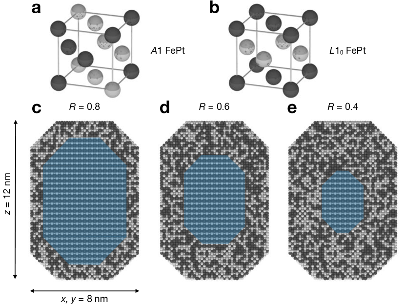
We construct elongated FePt grains with faceted surfaces following the method of Moreno et al. [23] which closely resemble realistic ones found in a typical HAMR recording medium [21]. The grains are elongated along the [001] lattice direction by a shape factor of 1.5. In order to replicate the effect of Pt surface segregation, the grains are structured with a core made of the ordered -phase FePt surrounded by a disordered -phase FePt shell. The grain size is fixed at 8 nm 8 nm 12 nm. The diameter of the core can be freely adjusted so as to reproduce varying degrees of ordering through a surface coupling effect between the and phase. The fractional core size of the grain is defined as where is the core diameter and the entire grain diameter. In simulations is varied between 0.05 and 0.95. The lower and upper bounds of represent two extreme cases: when the core consists of only one single atom, while when the grain has only one atomistic layer of the shell. Cross-sectional views of the core-shell grains with various core sizes are shown in Fig. 1. The unit cell of the fct -FePt is slightly compressed on the c-axis [24, 25, 26] while that of the fcc -FePt is not. For simulation efficiency and without altering any physical properties, a common unit cell is implemented for both phases with a uniform cubic shape and a lattice spacing of nm obtained from experiments and consistent with previous computational studies [27, 25, 26, 28].
Our simulations are carried out using the vampire atomistic simulation software package [29, 30] using a constrained Monte-Carlo (CMC) integrator [31]. The system magnetization can be constrained at an angle to the easy axis which is oriented along the -direction. At temperatures varying from 0K to 1000K, a full angular sweep is performed for from 0 to 180 degrees. The anisotropy constants are computed via the angular-dependent restoring torque [31, 32, 33]. For a uniaxial system, can be expressed as a power series: , where the constant can usually be omitted and and are the second and fourth-order anisotropy constants respectively. Therefore, by fitting to the torque computed from simulation output, the values of anisotropy constant(s) can be determined.
The spin Hamiltonian of the core-shell simulations is the sum of the respective Hamiltonian of the -phase core and of the -phase shell which, following the standard Heisenberg form, includes the exchange and anisotropy components without an external magnetic field term. In general the exchange can be written in tensor form where the encapsulates anisotropic exchange and the Dzyaloshinskii-Moriya interaction. In the case of the phase of FePt the exchange is isotropic while for the phase the exchange is anisotropic and can be expressed [34] as the sum of a diagonal tensor plus a two-ion anisotropy term . The Hamiltonian of the core and of the shell are given as follows:
| (1) |
where and are spin unit vectors, the (isotropic) exchange energy tensor between pair within the truncated-neighbor range , and and the local, in-plane single-site anisotropy of respective phase the numerical values of which in simulations are respectively set to 0 [35] and -0.097 meV/atom [34]. Unlike the exchange, the expression for anisotropy does not have to avoid double-counting, thus explaining the prefactor 2 of which cancels out the summation prefactor . In FePt, the exchange interaction extends further than strictly nearest-neighbours. However, since the exchange interaction strength decreases rapidly with increasing distance between neighbouring atoms, a reasonably good model includes the exchange interactions truncated after the next-next-nearest neighbours. The calculation of the truncated and is described the Supplemental Material Sec. S1 [36] which yields a Curie temperature of around K for both ordered and disordered phases comparable with experiment [37]. Numerical values of exchange energy, anisotropies, and other simulation parameters are tabulated in Table 1. Simulations are repeated 10 times to compute statistical values.
| Parameter | Notation | Unit | -phase | A1-phase |
|---|---|---|---|---|
| Atomistic spin moment | 3.23 | 3.23 | ||
| Local anisotropy | meV/atom | - 0.097 | 0 | |
| 2-ion anisotropy | meV/atom | 1.427 | 0 | |
| Total exchange [36] | J/link | |||
| CMC Equilibration steps | ||||
| CMC Total step |
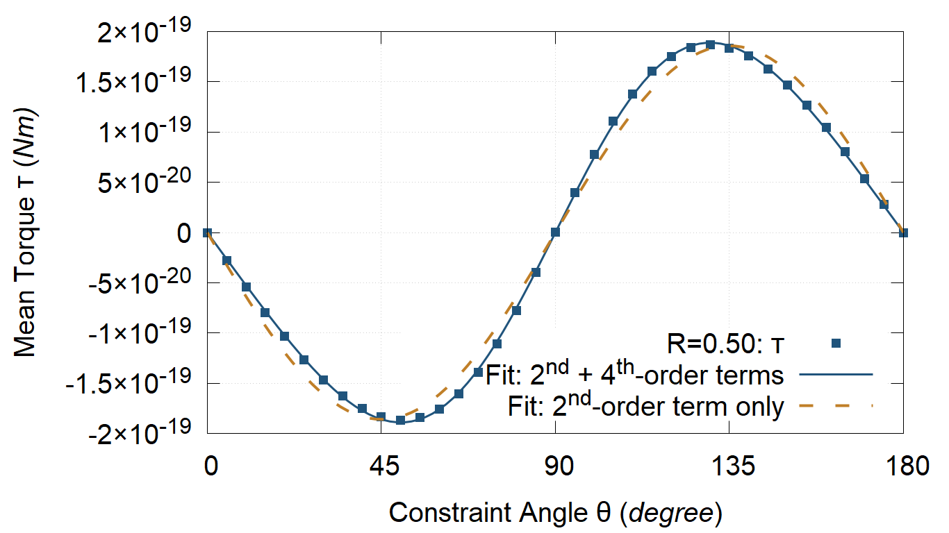
The magnetocrystalline anisotropy energy, if assumed to include only a second-order anisotropy term , would imply a restoring torque . However, our simulation results - a sample shown in Fig. 2(a) - demonstrate that a fit (dashed line) to the calculated torque is noticeably skewed from the simulation data (solid symbols). In contrast, when a fourth-order anisotropy term is added i.e. , the new torque fit (solid line) now matches the simulated data extremely well. The discernible skewing of the torque curve in comparison to a simple profile has been observed, without explanation, in a previous experimental study on FePt granular films [38]. In our simulations, however, the skewed torque curves in Fig. 2(a) are a clear indicator of the existence of a significant fourth-order anisotropy component in the core-shell grains.
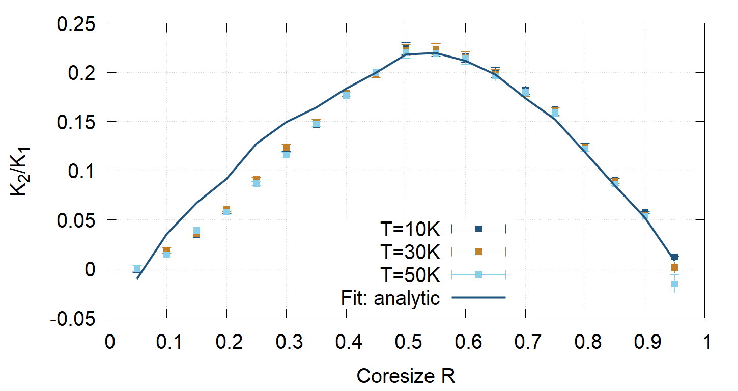
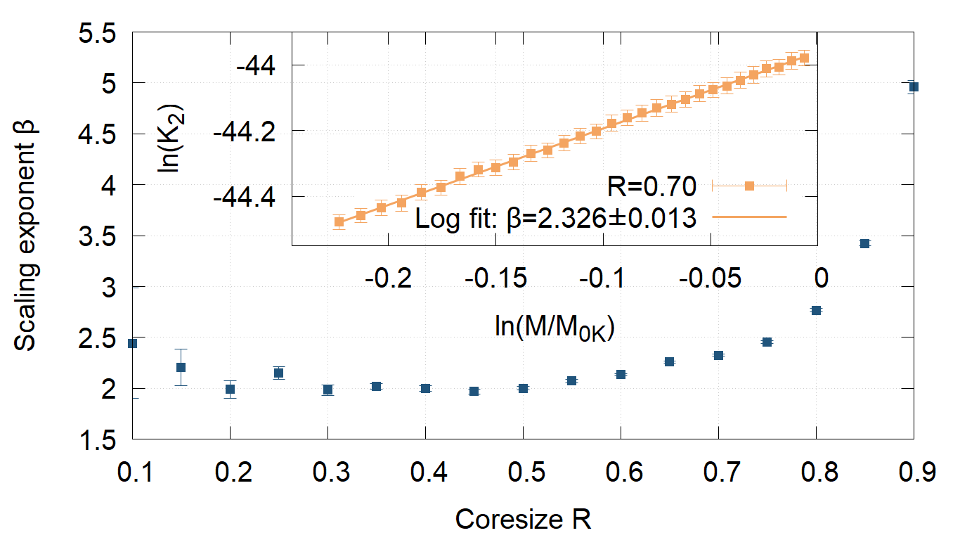
The magnitude of the temperature-dependent fourth-order anisotropy , expressed via the ratio, is found to be dependent on the core size with a non-monotonic variation that has not been reported elsewhere. Low-temperature data in Fig. 3 indicate that the magnitude of can be significant - exceeding 20% of - if the proportions of the two phases are comparable, or insignificant - just a few percent of - if one phase dominates. This result is intriguing because it essentially recaptures conflicting observations in literature [16, 12]. Additionally, the classical Callen-Callen power law [18] predicts the scaling behavior , where is the magnetization normalized against the saturated magnetization at 0 K. However, our simulation results conclusively contradict this prediction. The inset of Fig. 4 shows an example of scaling obtained from simulation for from which we find only. Overall, the scaling exponent is found to be consistently lower than the Callen-Callen predicted value of 10. The variation of for as a function of - in Fig. 4 - generally conforms to with exceptions seen in the two extreme cases and .
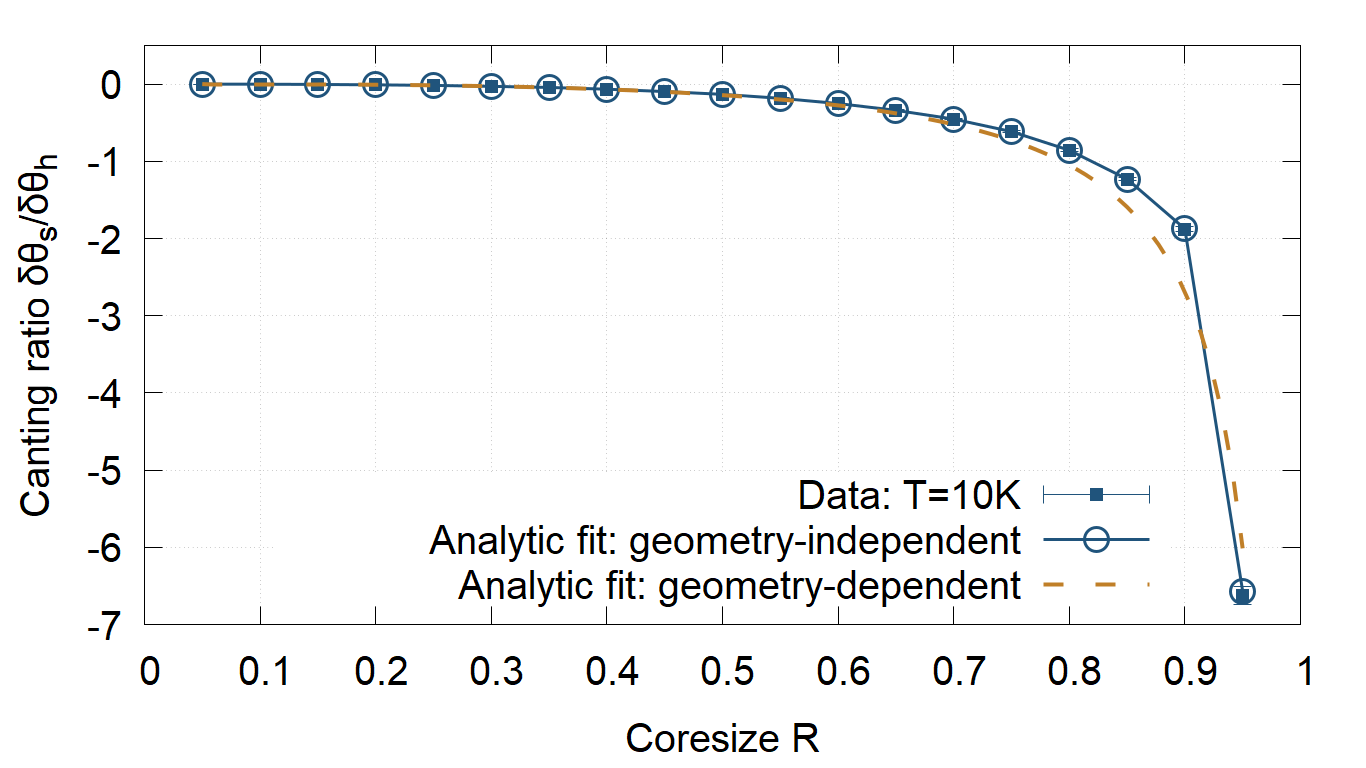
To discuss these two key results, we propose a simple analytic model which we show can explain the origin and behaviors of the fourth-order anisotropy constant in not only our simulated FePt core-shell system but also a generic material with soft/hard magnetic interlayers. A full description of the analytic model is provided in the Supplemental Material Sec. S2 [36], with the main points outlined as follows. The fundamental observation - illustrated in Fig. 2(b) - is that there exists a canting between the core and shell magnetization which minimizes the total (interlayer exchange and anisotropy) energy of the system. Consider a general core-shell system in which the core is made of a hard-magnetic material having an out-of-plane uniaxial anisotropy (per atom) and the shell a soft-magnetic material with negligible uniaxial anisotropy and make the simplifying assumption of coherent magnetization in both core and shell. To minimize the system total magnetic energy , the constrained angles of the magnetization and of the hard and soft-magnetic phase are allowed to deviate from the overall constraint angle by and respectively, which are sufficiently small to be treated as perturbations. Then can be expressed as:
| (2) |
where and are the number of spins in the core and the core/shell interface respectively, and the exchange integral. The first term in Eq. (2) is an anisotropy term and the second an interlayer exchange term which describes the exchange coupling between the core spins and the shell spins. Since and are the averaged contributions of all spins in each respective phase, their proportional sum must result in the system . Hence, Eq. (2) must be minimized subject to:
| (3) |
where is the fractional volume of the hard phase with being the total number of spins in the system. Note that for regular geometries, the geometry-independent variables , , and can be replaced by the core volume , the interface area , and the total volume respectively. Substitute and into Eq. (3) and solve to first-order approximation:
| (4) |
Analytic fits following from Eq. (4) for both the geometry-dependent case and the geometry-independence case are shown in Fig. 2(b). Because of the faceted shape of the simulated coreshell system, the geometry-dependent fit is seen to deviate from simulation data from while the geometry-independent fit matches the entire data range extremely well. Minimizing Eq. (2) subject to the constraint Eq. (3) leads to an expression of which explicitly includes both a second-order and a fourth-order anisotropy term the magnitude ratio of which is given by:
| (5) |
To expand the model, consider cases similar to the simulated coreshell FePt in which the dominant part of the core uniaxial anisotropy comes from a 2-ion anisotropy. This necessitates two further considerations. First, the 2-ion anisotropy is lost on the core/shell interface because of the loss of Pt neighbors from the next-immediate atomistic layer of the shell. Second, when the core is small, the in-plane anisotropy becomes dominant because of vanishing 2-ion anisotropy at the core surface. Take the simulated coreshell FePt for example, the in-plane anisotropy is the sum of the local single-site anisotropies of the and A1 phase, i.e. meV/atom, and manifests in the extreme case in Fig. 3 from which is seen to become negative. Incorporating these two extra considerations into the first term of Eq. (2) transforms its prefactor to , which subsequently modifies the expression in Eq. (5) to:
| (6) |
Fig. 3 shows the variation of with at low temperatures in which analytic predictions (solid line) are compared with simulation data (symbols). Both analytic and numerical variations share a similar non-monotonic form with a peak attained at . The agreement for is extremely good, while for the values appear to be slightly over-estimated by the analytic model. Nonetheless the overall agreement is highly satisfactory which supports the hypothesis that the fourth-order anisotropy arises from the core/shell spin canting and the exchange energy contribution at the core/shell interface.
Furthermore, the scaling exponent of to as shown in Fig. 4 can now be explained. Our analytic model finds that - with a detailed derivation given in the Supplemental Material Sec. S2 [36]. It has been established for -FePt that [34, 39, 40, 41, 42, 43, 44] and via mean-field calculations [45, 46]. The resulting scaling, therefore, reads thus reproducing in good agreement with simulation results. Finally, deviations from the analytic model for the two extreme cases and can be explained from the previously mentioned inherent nature of the grain structure in the respective cases. In the case, the core is so small that it consists of a single Fe atom which means the 2-ion anisotropy component of the phase completely vanishes, leaving the core with just the negative in-plane single-site Fe anisotropy. This explains the negative ratio at as seen in Fig. 3. Meanwhile, for the case, the shell is so thin that it has exactly one or two atomistic layers, hence invalidating the fundamental premise of the analytic calculations which assumes interactions up to the next-next-nearest neighbors. Hence, of the case was seen in Fig. 4 to increase exponentially in the range, albeit still significantly lower than the Callen-Callen’s predicted value of 10.
In summary, we have presented a comprehensive study of higher-order anisotropy in a phase-coupled /-FePt coreshell system. A fourth-order anisotropy is found to exist due to a combination of the canting of the core and shell magnetization and the exchange coupling at the core/shell interface. This fourth-order anisotropy is demonstrated to exhibit a strong dependence on the system geometry and scale with , which does not conform with the Callen-Callen power law. We formulate an analytic model to explain the origin and behaviors of this new fourth-order anisotropy from which a high level of agreement with numerical simulation is achieved. Overall, our findings provide substantial insights into a topic that has otherwise been lacking attention. Because anisotropy decides thermal stability of the writing medium, the significance of fourth-order anisotropy of -FePt can potentially translate to an issue of consideration for HAMR-related applications. Although investigated in the particular case of a /A1-FePt coreshell structure, the analytic model presented is valid for any combination of soft/hard materials. The phenomenon should therefore be observable in a wide variety of systems.
I Acknowledgments
The authors would like to thank Daniel Meilak for assistance with optimizing the simulated coreshell system. The financial support of the Advanced Storage Research Consortium (ASRC) is gratefully acknowledged. Sergiu Ruta acknowledges funding from the EPSRC TERASWITCH project (project ID EP/T027916/1). Sarah Jenkins acknowledges funding by the German Research Foundation (DFG) project No. 320163632. We are also grateful for computational support from the University of York High Performance Computing service, Viking, and the Research Computing team.
References
- Rottmayer et al. [2006] R. Rottmayer, S. Batra, D. Buechel, W. Challener, J. Hohlfeld, Y. Kubota, L. Li, B. Lu, C. Mihalcea, K. Mountfield, K. Pelhos, C. Peng, T. Rausch, M. Seigler, D. Weller, and X.-M. Yang, Heat-assisted magnetic recording, IEEE Transactions on Magnetics 42, 2417 (2006).
- McDaniel [2005] T. McDaniel, Ultimate limits to thermally assisted magnetic recording, Journal of Physics: Condensed Matter 17, R315 (2005).
- Weller et al. [2016] D. Weller, G. Parker, O. Mosendz, A. Lyberatos, D. Mitin, N. Schmidt, and M. Albrecht, Review article: FePt heat assisted magnetic recording media, Journal of Vacuum Science and Technology B, Nanotechnology and Microelectronics: Materials, Processing, Measurement, and Phenomena 34, 060801 (2016).
- Kryder et al. [2008] M. H. Kryder, E. C. Gage, T. W. McDaniel, W. A. Challener, R. E. Rottmayer, G. Ju, Y. Hsia, and M. F. Erden, Heat assisted magnetic recording, Proceedings of the IEEE 96, 1810 (2008).
- Nakaya et al. [2007] M. Nakaya, M. Kanehara, M. Yamauchi, H. Kitagawa, and T. Teranishi, Hydrogen-induced crystal structural transformation of FePt nanoparticles at low temperature, The Journal of Physical Chemistry C 111, 7231 (2007), https://doi.org/10.1021/jp072201w .
- Daalderop et al. [1991] G. H. O. Daalderop, P. J. Kelly, and M. F. H. Schuurmans, Magnetocrystalline anisotropy and orbital moments in transition-metal compounds, Phys. Rev. B 44, 12054 (1991).
- Sakuma [1994] A. Sakuma, First principle calculation of the magnetocrystalline anisotropy energy of FePt and CoPt ordered alloys, Journal of the Physical Society of Japan 63, 3053 (1994), https://doi.org/10.1143/JPSJ.63.3053 .
- Oppeneer [1998] P. Oppeneer, Magneto-optical spectroscopy in the valence-band energy regime: Relationship to the magnetocrystalline anisotropy, Journal of Magnetism and Magnetic Materials 188, 275 (1998).
- Ravindran et al. [2001] P. Ravindran, A. Kjekshus, H. Fjellvåg, P. James, L. Nordström, B. Johansson, and O. Eriksson, Large magnetocrystalline anisotropy in bilayer transition metal phases from first-principles full-potential calculations, Phys. Rev. B 63, 144409 (2001).
- Shick and Mryasov [2003] A. B. Shick and O. N. Mryasov, Coulomb correlations and magnetic anisotropy in ordered CoPt and FePt alloys, Phys. Rev. B 67, 172407 (2003).
- Solovyev et al. [1995] I. V. Solovyev, P. H. Dederichs, and I. Mertig, Origin of orbital magnetization and magnetocrystalline anisotropy in TX ordered alloys (where T=Fe,Co and X=Pd,Pt), Phys. Rev. B 52, 13419 (1995).
- Okamoto et al. [2002] S. Okamoto, N. Kikuchi, O. Kitakami, T. Miyazaki, Y. Shimada, and K. Fukamichi, Chemical-order-dependent magnetic anisotropy and exchange stiffness constant of FePt (001) epitaxial films, Phys. Rev. B 66, 024413 (2002).
- Weller et al. [2000] D. Weller, A. Moser, L. Folks, M. Best, W. Lee, M. Toney, M. Schwickert, J.-U. Thiele, and M. Doerner, High Ku materials approach to 100 , Magnetics, IEEE Transactions on 36, 10 (2000).
- Bublat and Goll [2010] T. Bublat and D. Goll, Temperature dependence of the magnetic properties of -FePt nanostructures and films, Journal of Applied Physics 108, 113910 (2010), https://doi.org/10.1063/1.3512906 .
- Shima et al. [2004] T. Shima, K. Takanashi, Y. K. Takahashi, and K. Hono, Coercivity exceeding 100 in epitaxially grown FePt sputtered films, Applied Physics Letters 85, 2571 (2004), https://doi.org/10.1063/1.1794863 .
- Inoue et al. [2006] K. Inoue, H. Shima, A. Fujita, K. Ishida, K. Oikawa, and K. Fukamichi, Temperature dependence of magnetocrystalline anisotropy constants in the single variant state of -type FePt bulk single crystal, Applied Physics Letters 88, 102503 (2006), https://doi.org/10.1063/1.2177355 .
- Richter et al. [2011] H. J. Richter, O. Hellwig, S. Florez, C. Brombacher, and M. Albrecht, Anisotropy measurements of FePt thin films, Journal of Applied Physics 109, 07B713 (2011), https://doi.org/10.1063/1.3536459 .
- Callen and Callen [1966] H. Callen and E. Callen, The present status of the temperature dependence of magnetocrystalline anisotropy, and the power law, Journal of Physics and Chemistry of Solids 27, 1271 (1966).
- Chatterjee et al. [2014] B. K. Chatterjee, C. K. Ghosh, and K. K. Chattopadhyay, Temperature dependence of magnetization and anisotropy in uniaxial nanomagnets: Deviation from the Callen-Callen power law, Journal of Applied Physics 116, 153904 (2014), https://doi.org/10.1063/1.4898089 .
- Miura and Sakuma [2018] D. Miura and A. Sakuma, Power law analysis for temperature dependence of magnetocrystalline anisotropy constants of magnets, AIP Advances 8, 075114 (2018), https://doi.org/10.1063/1.5021969 .
- Sepehri-Amin et al. [2017] H. Sepehri-Amin, H. Iwama, G. Hrkac, K. Butler, T. Shima, and K. Hono, Pt surface segregation in -FePt nano-grains, Scripta Materialia 135, 88 (2017).
- Barucca et al. [2017] G. Barucca, T. Speliotis, G. Giannopoulos, D. Niarchos, B. Rutkowski, A. Czyrska-Filemonowicz, E. Agostinelli, S. Laureti, A. Testa, and G. Varvaro, Magnetic anisotropy phase-graded -FePt films on amorphous glass substrates, Materials and Design 123, 147 (2017).
- Moreno et al. [2020] R. Moreno, S. Poyser, D. Meilak, A. Meo, S. Jenkins, V. K. Lazarov, G. Vallejo-Fernandez, S. Majetich, and R. F. L. Evans, The role of faceting and elongation on the magnetic anisotropy of magnetite fe3o4 nanocrystals, Scientific Reports 10, 10.1038/s41598-020-58976-7 (2020).
- Kabir et al. [2015] A. Kabir, J. Hu, V. Turkowski, R. Wu, R. Camley, and T. S. Rahman, Effect of structure on the magnetic anisotropy of -FePt nanoparticles, Physical Review B 92, 10.1103/physrevb.92.054424 (2015).
- Lyubina et al. [2006] J. Lyubina, O. Isnard, O. Gutfleisch, K.-H. Müller, and L. Schultz, Ordering of nanocrystalline Fe–Pt alloys studied by in situ neutron powder diffraction, Journal of Applied Physics 100, 094308 (2006), https://doi.org/10.1063/1.2360151 .
- Klemmer et al. [2002] T. J. Klemmer, N. Shukla, C. Liu, X. W. Wu, E. B. Svedberg, O. Mryasov, R. W. Chantrell, D. Weller, M. Tanase, and D. E. Laughlin, Structural studies of FePt nanoparticles, Applied Physics Letters 81, 2220 (2002), https://doi.org/10.1063/1.1507837 .
- Loc Nguyen et al. [2006] H. Loc Nguyen, L. E. M. Howard, G. W. Stinton, S. R. Giblin, B. Tanner, I. Terry, A. K. Hughes, I. M. Ross, A. Serres, and J. S. O. Evans, Synthesis of size-controlled fcc and fct FePt nanoparticles, Chemistry of Materials 18, 6414–6424 (2006).
- Aksornniem et al. [2015] S. Aksornniem, R. Evans, R. Chantrell, and R. Silapunt, Magnetic switching in BPM, TEAMR, and modified TEAMR by using dielectric underlayer media, IEEE Transactions on Magnetics 52, 1 (2015).
- vam [2020] vampire software package v5 available from https://vampire.york.ac.uk/, (2020).
- Evans et al. [2014] R. F. L. Evans, W. J. Fan, P. Chureemart, T. A. Ostler, M. O. A. Ellis, and R. W. Chantrell, Atomistic spin model simulations of magnetic nanomaterials, J. Phys.: Condens. Matt. 26, 103202 (2014).
- Asselin et al. [2010] P. Asselin, R. F. L. Evans, J. Barker, R. W. Chantrell, R. Yanes, O. Chubykalo-Fesenko, D. Hinzke, and U. Nowak, Constrained Monte Carlo method and calculation of the temperature dependence of magnetic anisotropy, Phys. Rev. B 82, 054415 (2010).
- Wang et al. [1996] X. Wang, R. Wu, D.-s. Wang, and A. J. Freeman, Torque method for the theoretical determination of magnetocrystalline anisotropy, Phys. Rev. B 54, 61 (1996).
- Wu and Freeman [1999] R. Wu and A. Freeman, Spin–orbit induced magnetic phenomena in bulk metals and their surfaces and interfaces, Journal of Magnetism and Magnetic Materials 200, 498 (1999).
- Mryasov et al. [2005] O. N. Mryasov, U. Nowak, K. Y. Guslienko, and R. W. Chantrell, Temperature-dependent magnetic properties of FePt: Effective spin hamiltonian model, Europhysics Letters (EPL) 69, 805 (2005).
- Schaaf et al. [2007] P. Schaaf, K. Zhang, C. Lange, A. Holz, M. Weisheit, and S. Faehler, Structure and anisotropy of epitaxial fcc FePt films, Applied Surface Science 253, 8107 (2007).
- [36] See Supplemental Material at [url will be inserted by publisher] for the calculation of the truncated exchange and 2-ion anisotropy, and the full description of the Analytic model.
- Hovorka et al. [2012] O. Hovorka, S. Devos, Q. Coopman, W. J. Fan, C. J. Aas, R. F. L. Evans, X. Chen, G. Ju, and R. W. Chantrell, The Curie temperature distribution of FePt granular magnetic recording media, Applied Physics Letters 101, 052406 (2012), https://doi.org/10.1063/1.4740075 .
- Saito et al. [2021] T. Saito, K. K. Tham, R. Kushibiki, T. Ogawa, and S. Saito, Separate quantitative evaluation of degree of order and perpendicular magnetic anisotropy for disorder and order portion in FePt granular films, AIP Advances 11, 015310 (2021), https://doi.org/10.1063/9.0000139 .
- Skomski et al. [2006] R. Skomski, O. N. Mryasov, J. Zhou, and D. J. Sellmyer, Finite-temperature anisotropy of magnetic alloys, Journal of Applied Physics 99, 08E916 (2006), https://doi.org/10.1063/1.2176892 .
- Skomski et al. [2005] R. Skomski, A. Kashyap, and J. Zhou, Atomic and micromagnetic aspects of magnetism, Scripta Materialia 53, 389 (2005).
- Skomski et al. [2003] R. Skomski, A. Kashyap, and D. Sellmyer, Finite-temperature anisotropy of PtCo magnets, Magnetics, IEEE Transactions on 39, 2917 (2003).
- Staunton et al. [2004] J. B. Staunton, S. Ostanin, S. S. A. Razee, B. L. Gyorffy, L. Szunyogh, B. Ginatempo, and E. Bruno, Temperature dependent magnetic anisotropy in metallic magnets from an ab initio electronic structure theory: -ordered FePt, Phys. Rev. Lett. 93, 257204 (2004).
- Thiele et al. [2002] J.-U. Thiele, K. R. Coffey, M. F. Toney, J. A. Hedstrom, and A. J. Kellock, Temperature dependent magnetic properties of highly chemically ordered films, Journal of Applied Physics 91, 6595 (2002), https://aip.scitation.org/doi/pdf/10.1063/1.1470254 .
- Evans et al. [2020] R. F. L. Evans, L. Rózsa, S. Jenkins, and U. Atxitia, Temperature scaling of two-ion anisotropy in pure and mixed anisotropy systems, Phys. Rev. B 102, 020412 (2020).
- Atxitia et al. [2010] U. Atxitia, D. Hinzke, O. Chubykalo-Fesenko, U. Nowak, H. Kachkachi, O. N. Mryasov, R. F. Evans, and R. W. Chantrell, Multiscale modeling of magnetic materials: Temperature dependence of the exchange stiffness, Physical Review B 82, 134440 (2010).
- Atxitia et al. [2007] U. Atxitia, O. Chubykalo-Fesenko, N. Kazantseva, D. Hinzke, U. Nowak, and R. W. Chantrell, Micromagnetic modeling of laser-induced magnetization dynamics using the Landau-Lifshitz-Bloch equation, Applied Physics Letters 91, 232507 (2007), https://doi.org/10.1063/1.2822807 .