Linear colossal magnetoresistance driven by magnetic textures in \chLaTiO_3 thin films on \chSrTiO_3
Abstract
Linear magnetoresistance (LMR) is of particular interest for memory, electronics, and sensing applications, especially when it does not saturate over a wide range of magnetic fields. One of its principal origins is local mobility or density inhomogeneities, often structural, which in the Parish-Littlewood theory leads to an unsaturating LMR proportional to mobility. Structural disorder, however, also tends to limit the mobility and hence the overall LMR amplitude. An alternative route to achieve large LMR is via non-structural inhomogeneities which do not affect the zero field mobility, like magnetic domains. Here, linear positive magnetoresistance caused by magnetic texture is reported in \chLaTiO3/\chSrTiO3 heterostructures. The LMR amplitude reaches up to 6500% at 9T. This colossal value is understood by the unusual combination of a very high thin film mobility, up to 40 000 cm2/V.s, and a very large coverage of low-mobility regions. These regions correlate with a striped magnetic structure, compatible with a spiral magnetic texture in the \chLaTiO3 film, revealed by low temperature Lorentz transmission electron microscopy. These results provide a novel route for the engineering of large-LMR devices.
I Introduction
In conventional metals, the magnetoresistance (MR) commonly exhibits quadratic field dependence at low magnetic fields and saturates at high fields [1]. This classical MR is usually limited in amplitude to a few percent at 10T [2]. Many effects, however, are known to impact magnetoresistance: a magnetic ground state (ferromagnetism (FM) [3, 4, 5, 6, 7, 8], antiferromagnetism (AFM) [9, 10]), Dirac physics [11, 12, 13], Landau levels [14, 15], or spatial inhomogeneities for instance [16, 17, 18, 19, 20, 21], can lead to modifications of the amplitude or the magnetic field dependency of the MR. In particular, Dirac physics in topological insulators [11, 12, 13] and semimetals [22, 23, 24, 25, 26, 27, 28, 29, 30] or spatial inhomogeneities [18, 19, 20, 31] can result in linear magnetoresistance (LMR) behaviour [1, 32, 16, 17]. Beyond its relevance for fundamental research, the non-saturating nature of LMR makes it also interesting for sensing, electronics and memory applications. In this context, systems with large LMR are highly desirable.
Amongst other theories, non-saturating LMR can be understood semi-classically in the Parish-Littlewood framework by a random resistor network model that mimics a disordered and strongly inhomogeneous conductor system [16, 17]. This model can be extended to systems with local low-mobility or low-carrier density regions acting as guiding centres for the carrier paths [18, 19, 20]. This model predicts a LMR whose amplitude depends linearly on the carrier mobility and on the guiding center density[18].
Guiding center regions are, however, usually related to local structural defaults or disorder [18, 20], which limit the system mobility and hence the amplitude of the resulting LMR to about 200% at 9T [18, 19, 29]. Other mechanisms inducing local inhomogeneities without affecting the zero-field mobility could therefore lead to a much stronger effect. In particular, magnetically textured regions could lead to local mobility inhomogeneities through magnetic scattering, while potentially retaining high mobility since the crystalline quality would not be affected. More recently, LMR has been observed together with ferromagnetic (FM) order [33] or magnetic signatures (anomalous Hall effect [34, 35]), with high amplitudes of about 1000% at 9T. However, tangible evidence of a link between magnetic structure and LMR has yet to be ascertained.
Here we report on a linear positive magnetoresistance in \chLaTiO3/\chSrTiO3 (LTO/STO) heterostructures with high mobility (up to 40 000 cm2/V.s). The MR amplitude is much higher than in most oxide systems (up to 6500% at 9T), and falls within the range of the colossal magnetoresistance. This linear colossal magnetoresistance (LCMR) is found to be compatible with the Parish-Littlewood theory, with an extremely high coverage of low mobilities regions, between 50% and nearly 90%. Through low temperature transmission electron microscopy (TEM) in magnetic field, the origin of these regions is traced back to a magnetic uniaxial stripe pattern, oriented along well-defined crystallographic axes. Those stripes are compatible with spiral magnetic order in the LTO layer. Our work reveals that magnetic texture can induce linear magnetoresistance with colossal amplitude in high mobility devices such as LTO/STO heterostructures.
II Thin film samples
Our LTO thin films were grown on TiO2 terminated STO substrates using pulsed laser deposition. The structures where pre-patterned with optical lithography similarly to Ref.[36] to achieve crystalline LTO in Hall bar shapes as seen in Figure 1(a),(b) of different lengths and widths.
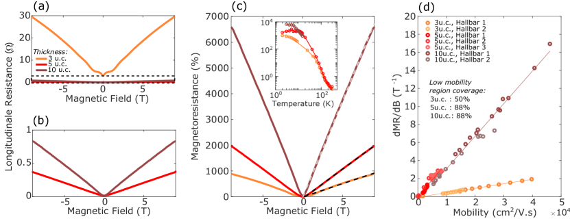
We first consider standard transport and Hall characterisation to identify the origin of the main conducting channel. Figure 1(c) shows the temperature dependence of the resistivity for different film thicknesses and Hall bar geometries. The resistivity of different Hall bars is well reproducible for a specific film thickness with small variations accounting for spatial inhomogeneity of the films. We observe that the resistivity decreases significantly from the 3u.c. to the 5u.c. film but stays approximately constant for both the 5u.c. and the 10u.c. samples. All three investigated thicknesses exhibit clear metallic behaviour. The samples further show a high residual resistance ratio , implying very clean, high quality samples with only trace amounts of impurities and structural disorder. The Hall effect, shown in Figure 1(d), is linear at room temperature, gradually evolving into an s-shape with decreasing temperature, which most probably indicates the presence of several bands contributing to transport. We extract the total carrier density from the high field asymptotic slope at 9T of the Hall resistance (), for the 3u.c. and for both the 5u.c. and 10u.c. films at high temperature. These very large charge carrier densities are found to be almost temperature independent as shown in Figure 1(e). The low temperature variations arise as the Hall effect starts to display non-linearities. Interestingly, the transport mobilities (Figure 1(f)) extracted from the Drude formula as (where is the conductivity) are found to be up to 40 000 cm2/V.s at low temperatures reflecting the high sample quality of our thin films.
Next we discuss the spatial location of the conduction electrons in our LTO/STO heterostructures for which three distinct conduction channels are possible: through an interface 2D electron gas (2DEG) between LTO and STO, through unintentionally doped STO, and through bulk LTO. First, the extremely high equivalent 2D carrier density of cm-2 extracted from the Hall measurements for the 5u.c. and 10u.c. samples makes a pure 2DEG scenario highly unlikely. Typical carrier densities in STO-based 2DEGs are usually one to two magnitudes smaller [37, 34]. This conclusion is corroborated by the absence of a superconducting transition down to 0.2 K (data not shown), which has previously been reported for doped STO as well as for an interface 2DEG in LTO/STO [38, 37]. On the other hand, characterization of the Titanium valence in the LTO film by x-ray photoelectron spectroscopy (XPS) reveals a strong 4+ signal with a sizable 3+ admixture (see Supp. Info. I). This places the doping state of the LTO film far from the nominal Mott insulator (expected for a purely Titanium 3+ valence) and well into the metallic regime [39]. We therefore believe that the transport is dominated by the metallic bulk of the LTO films.
III Linear Colossal Magnetoresistance
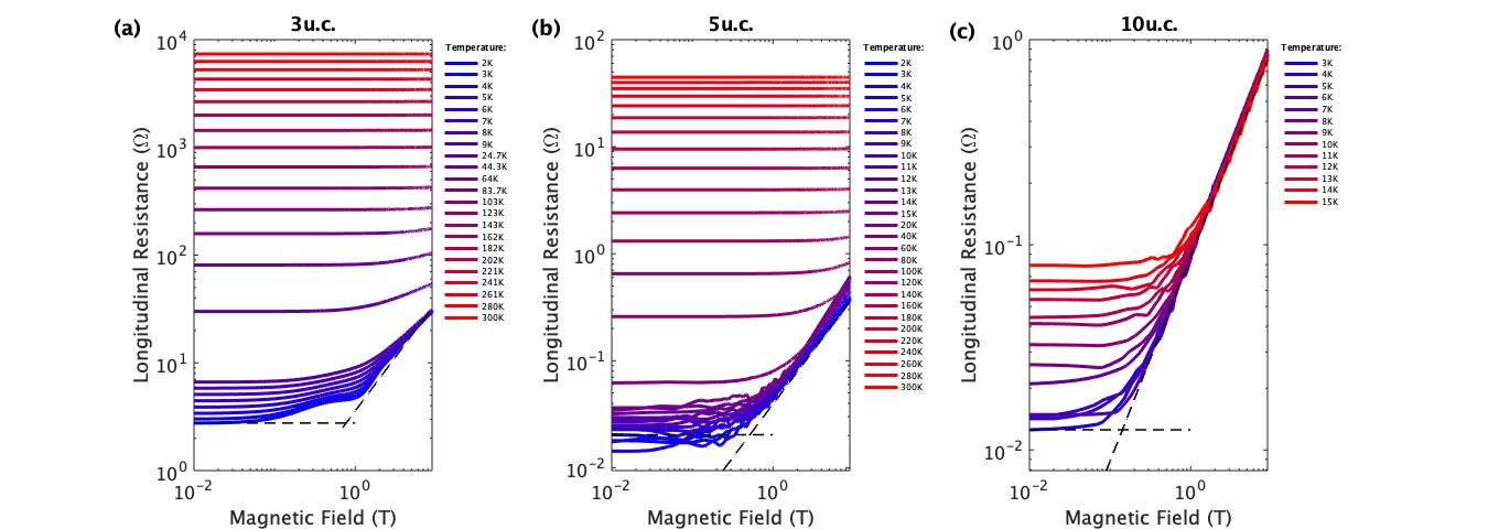
We now turn to an analysis of the magnetoresistance. Figure 2(a) shows the dependence of the longitudinal resistance as a function of the perpendicular magnetic field for Hall bars of different thicknesses studied at 3K. The 3u.c. sample displays a strong positive MR, and further exhibits low-field features that point to Sondheimer oscillations (see Supp. Info. II). The relative increase is even stronger for the 5 and 10u.c. samples as shown in Figure 2(b). Furthermore, it can be seen from these measurements that the response is not just colossal but also linear with remarkable precision, starting at magnetic fields well below 1T and with no visible saturation up to at least 11T. All samples studied systematically exhibit this non-saturating linear magnetoresistance. To better display the relative increase of the resistance, we plot the MR in % calculated as:
MR amplitudes of more than 700% at B=9T for the 3u.c. and up to 6500% at B=9T for the 10u.c. film are observed, which fall within the range of the colossal magnetoresistance [40]. The MR therefore increases sizably with increasing thickness going from the 3u.c. to 10u.c film. In addition the linear regime sets in for field values that get smaller as the thickness is increased (see Supp. Info. III). This thickness evolution corroborates our conclusion that the transport involves carrier motion in the LTO film.
In the inset of Figure 2 we plot the MR at 9T versus temperature in a log-log scale. The MR amplitude shows a saturation below 10K and a strong decrease with increasing temperature. In addition, a departure from the linearity is measured for the magnetoresistance and becomes more parabolic-like above K (see Supp. Info. III).
We see a marked contrast between our findings and those reported in Ref.[41] which showed the appearance of Shubnikov-de-Haas oscillations starting around 1T and non-linear magnetoresistance of at most 400% at 9T [41]. The origin of this discrepancy is unclear. Our observation of an LMR is, however, fully reproducible over several samples of varying thickness and several Hall bar geometries. The absence of Shubnikov-de-Haas oscillations in our samples despite large transport mobilities, which should allow their observation in our field range, could point to inelastic scattering in our films due to strong spin-orbit coupling. This effect can cause the quantum mobility (which determines the onset of the Shubnikov-de-Haas regime) to be reduced compared to the transport mobility [42].
The occurrence of LMR has been previously observed in studies on other materials, albeit with significantly reduced amplitude as compared to our results [43, 44, 45]. The scenarios that have been proposed to explain the LMR involve either quantum or classical effects. In the case of a quantum origin [1], the linear MR appears in the limit, when all the electrons occupy the lowest Landau level. The MR is calculated as , with being the carrier density and the concentration of scattering centers. This expression is valid for and with an electron density of , the field at which electrons coalesce into a single Landau level is T [18]. This is far greater than the values in our systems which show an onset well below 1T.
The classical model, on the other hand, describes the origin of the LMR as distortions in the current paths that can be induced by microscopic spatial fluctuations in the carrier mobility [16]. Such a classical linear MR has been observed in highly disordered systems [46] as well as in high mobility systems with weak disorder [47] where the carrier concentration is too high to freeze the electrons in the lowest Landau level (quantum limit). In this model the system is made of low-mobility regions embedded in a high mobility conductor. The stochastic behaviour of the electron trajectories around the low-mobility regions induces the LMR [18, 48, 20]. In this theory, at high magnetic field the amplitude of the LMR varies linearly with the average global mobility (determined at zero field), as given by the following equation:
| (1) |
where is the average radius of the regions, is the distance between the regions and is the mobility.
To validate this scenario in our system, we have plotted the linear slope of the MR curve with respect to the mobility. Thanks to the strong temperature dependence of the Hall mobility in our samples, we can observe the dependence of the LMR slope over a broad mobility range (Figure 2(d)). It is clearly seen that the LMR slope depends linearly on the Hall mobility as expected from Eq. (1). Moreover, different Hall bar geometries with identical thickness consistently fall on the same curve, indicating perfect reproducibility between different samples, also with respect to their inhomogeneity. This linear dependence confirms the presence of low-mobility regions as the origin of the LMR with the mobility in our samples. Using equation (1), we can extract the coverage of these low-mobility islands via the dependence of the slope of the LMR on the mobility (). We obtain coverages ranging from 50% for the 3u.c. sample to 88% for both the 5 and the 10u.c. samples. This is 2 to 6 times larger than coverages reported so far [19, 18].
The amplitudes of the LMR in our samples are very large for systems with such high coverages of low-mobility regions. The reason for this lies in the combination of both the high background mobility and the substantial coverage of low-mobility regions. As can be seen from Eq. (1), in the guiding centres model, the amplitude of the LMR is proportional to both Hall mobility () and region coverage. In standard thin films and 2DEGs, low-mobility regions usually originate from local disorder, whether structural or induced by impurities [18]. As such, an increase in the Hall mobility involves a decrease in the island concentration and conversely. This results in a balance which tends to limit the LMR amplitude. In our system however, we observe both a very high mobility and an exceptional coverage of low-mobility regions. This unusual combination allows us to reach LMR with colossal amplitudes.
However, the combination of very high mobility and large coverage of guiding centres seems incompatible with a structural origin of the low-mobility islands. In the next section, the nature of those low-mobility regions is discussed.
IV Magnetic stripe pattern
In order to search for relevant nanometer scale inhomogeneities in the temperature regime where the LCMR is observed, we carried out cryogenic Lorentz transmission electron microscopy (LTEM) on 10 u.c. thick \chLaTiO3 films (see Figure 3(a) and methods). To reveal the nature of the observed contrast variations, we investigated their dependence on temperature, external magnetic field and defocus at a dedicated continuous-flow liquid Helium-cooled TEM instrument [49].
At low temperature, under zero magnetic field only small dark dots distributed across the entire field of view are observed (see Figure 3(b)). Those are invariant with temperature and field and may be associated to impurities, precipitates or point defects. Under external magnetic field, a stripe-like uniaxial modulation of the LTEM contrast is however visible at out-of-focus conditions. This stripe pattern is observed close to bending contours (i.e., loci of locally fulfilled Bragg conditions, which naturally occur in thin strained TEM lamellas, see Figure 3(a),(c)). The modulation has a periodicity of nm within the resolution of our measurement (Figure 3(i)). Correlated electron diffraction data further reveals that the modulation direction aligns with the axis of the underlying \chSrTiO3 sample (corresponding to the orientation of the orthorhombic \chLaTiO3 film), i.e. along the Ti-O-Ti direction (Figure 3(j) and Suppl. Info. IV). The observed contrast modulation is strongly field dependent and virtually vanishes at zero external field (Figure 3(b),(c)). Moreover, the contrast vanishes in focus and changes sign upon inverting the sign of the focus (see Suppl. Info. IV). These observations are compatible with the presence of a uniaxial magnetic texture in the \chLaTiO3 films (see Suppl. Info. IV for further discussion of the contrast mechanism). To our knowledge, the existence of such a magnetic structure has not been previously reported in \chLaTiO3.
To investigate the stability of the magnetic stripe texture, we performed temperature dependent measurements. The stripes appear stable between 8 K and 20 K. Above 20 K they start to disappear, where the shrinking of the modulated regions may be inhomogeneous. For instance, modulation associated to bending contour I seems to be gone at around 35K (not shown), whereas that associated to contour II persists up to 80K. We observe no clear temperature dependence of the periodicity of the modulation.
Owing to the unique contrast amplification mechanism, which makes the stripes only visible around the bending contours (see Suppl. Info. IV), we cannot determine the fractional coverage of the modulation. However, the shifting of the modulation with bending contour II in Figs. 3(d-g) indicates a very large coverage of several tens of percent.
V Discussion
The uniaxial magnetic texture in the LTO film observed in LTEM covers a sizable area of the sample with a morphology that evolves with temperature above 20 K up until 80 K when the pattern disappears. These features mirror those ascribed to the low mobility regions in magnetotransport. In the following we discuss a possible origin of the magnetic texture as well as its impact on magnetotransport.
Magnetic stripes were reported in STO-based heterostructures, originating from ferroelastic domain walls in STO substrates [50, 51]. These domains however have typical sizes ranging from 5 to 15 m [50, 51], which is more than one order of magnitude larger than those we observe. This casts some doubt on their role to explain our modulation. Experimental [52] and theoretical [53] investigations established that bulk LaTiO3 orders antiferromagnetically (AF) at low temperature with canted Ti3+ moments owing to orthorhombic distortions, resulting in a small ferromagnetic component. Another possible explanation for the uniaxial modulation would then be ferromagnetic stripes with out-of-plane anisotropy. However, this scenario would imply out-of-plane magnetic domains separated by Bloch-like domain boundaries [54], both of which would generate no contrast in our LTEM configuration.
Based on the large Rashba spin-orbit coupling of the LTO thin film [41], we propose an alternative scenario where a spiral magnetic phase is stabilized by the double exchange process between mobile carriers and static moments, owing to a large Hund’s coupling energy [55, 56]. According to the double exchange scenario, the spins of the mobile carriers are locked to the local Ti3+ magnetic moments. The ground state is determined by a balance between an effective exchange term (with the hopping energy and the mobile electronic fraction per Ti atom), a Dzyaloshinskii-Moriya (DM) term (where is the interfacial Rashba-like spin-orbit energy) and an exchange anisotropy term [55, 56]. The corresponding effective spin Hamiltonian reads:
| (2) | ||||
where corresponds to the out-of-plane [001] direction, is the in-plane Ti-O-Ti distance, and and denote the Ti-O-Ti bond directions (see Supplementary Material for further details). For the set of parameters relevant to the LTO/STO interface ( meV [57], meV – [58]), the ground state configuration is a spiral, propagating with a wavevector parallel to the Ti-O-Ti bonds ( or direction in the pseudocubic LTO frame) and polarized in a plane parallel to the interface [55, 56]. Here, in constrast to the \chLaAlO3/\chSrTiO3 interface case when the DM term is in-plane, octahedral rotations in LTO/STO allow an out-of-plane DM contribution. This is important in our case since only an in-plane spiral (like the one shown in Figure 3(j)) would result in a LTEM contrast. We calculate the pitch of the spiral to be nm. Both the pitch and the modulation direction are in good agreement with our LTEM measurements.
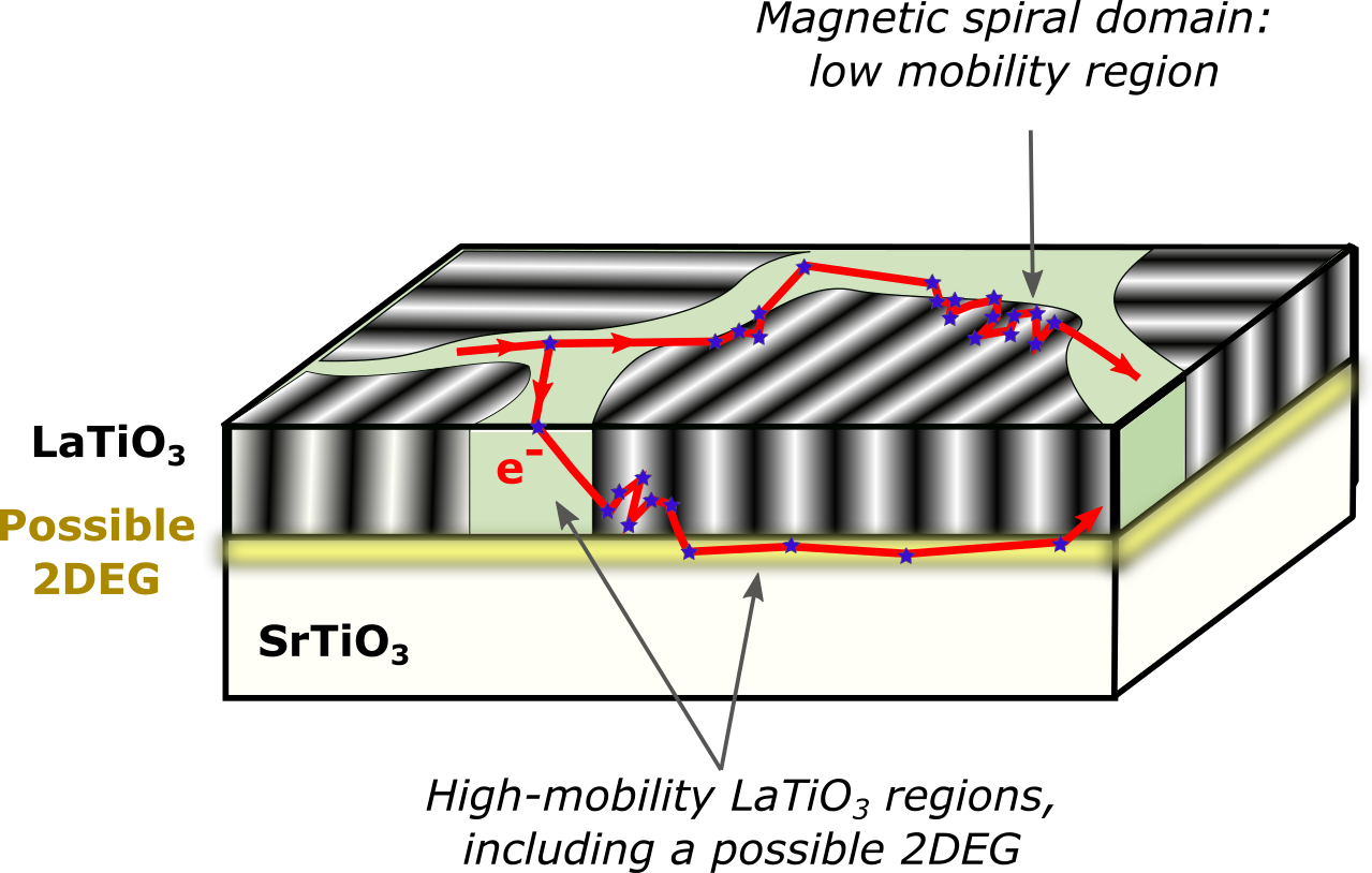
The existence of the magnetic spiral state in LTO strongly influence magnetotransport. In particular, in the magnetic region, magnetic scattering can significantly increase the scattering rate. Considering that a spin-spiral texture consist of successive interfaces between magnetic slabs with small tilt of the magnetisation between them, we estimate that the scattering rate in the spin-spiral domains is more than one order of magnitude larger than in the rest of the sample (see Suppl. Info. V). In the framework of the Parish-Littlewood scenario[16, 18], we propose that the low-mobility regions could correspond to the magnetic regions of the LTO film, where electrons would experience spin-scattering (see Figure 4). This would naturally explain the high calculated coverage. The high-mobility channels could be comprised of either non-magnetic LTO regions, of a confined 2DEG or unintentionally doped STO layer, where the high-mobility would not be impacted as much by magnetic scattering. Since the proportion of LTO in the total conducting volume only increase with film thickness, the low-mobility region coverage would also increase with thickness, as is observed. The exact influence of a three-dimensional electron motion on the Parish-Littlewood theory is unclear, and should be further examined theoretically.
VI Conclusion:
To summarise our findings, \chLaTiO3 thin films on \chSrTiO3 were investigated using magnetotransport and transmission electron microscopy measurements. The main result is the observation of a non-saturating linear magnetoresistance, with a colossal amplitude up to 6500% at 9T. This very large effect is understood as resulting from the combination of high carrier mobility (40 000 cm2/V.s) with an extreme coverage of guiding-centre regions of 49% up to 89%. These lower-mobility regions are tied to a striped pattern of magnetic origin in the \chLaTiO3 film revealed by Lorentz TEM. The observed striped pattern is shown to be compatible with spiral magnetism. Our study establishes a link between non-saturating linear colossal magnetoresistance and complex magnetic structure. This result suggests a new design concept for devices with large linear magnetoresistance in magnetic materials and heterostructures. We further expect it to trigger further theoretical interest on linear magnetoresistance in inhomogeneous and magnetic systems.
VII Experimental Section
Growth
For growth a laser flux of 1.5 J.cm-2 and a polycrystalline La2Ti2O7 target at a distance of 55 mm from the substrate were employed. Thin films with different thicknesses of 3, 5 and 10 unit cells (u.c.) were grown into Hall bars, with lengths of 20, 40, 60 and 80 m and widths of 50, 100 and 150 m. During growth, the band filling of LTO can be tuned by excess oxygen doping [39]. All samples investigated were grown under high oxygen background pressure ( mbar), inducing over oxidation and thus producing a correlated metallic system. Further details can be found in the supplementary information section 1. The samples were glued to chip carriers and wire bonded for the magnetotransport measurements.
Transport measurements
Magnetotransport experiments were performed using a Quantum Design physical properties measurement system (PPMS) in pseudo-AC mode, and with a - dilution refrigerator with the magnetic field applied perpendicular to the films, using standard lock-in techniques. The transverse magnetoresistance (MR) was studied with magnetic fields up to 11T, generated by a superconducting magnet. In Figures 1 and 2, several Hallbars of different sizes are investigated: Hallbars 1 are 20x50 m, Hallbars 2 are 20x80 m, and Hallbars 3 are 50x150 m.
TEM preparation and measurements
Electron-transparent TEM samples have been prepared by a classical back-side thinning procedure consisting of (A) manual coarse mechanical grinding, (B) dimpling, and (C) final Ar ion milling using a precision ion polishing system (PIPS 691, Gatan Inc., US) until a hole appears. All thinning steps have been applied from the back (substrate) side of the sample in order to preserve the \chLaTiO3 film. The latter was verified by employing TEM-EDX, which showed the presence of La throughout the entire sample region of interest. Cryogenic TEM investigations were carried out at the JEOL 2010F Dresden special instrument [49] operated at an acceleration voltage of 200 kV. The microscope is fitted with a custom-made continuous-flow liquid Helium cryostat enabling stable cooling for several days while varying temperature, which is essential for the above studies. External magnetic fields were applied by exciting the objective lens coils of the TEM. Lorentz imaging (i.e., out-of-focus and small external field conditions) was set by varying the first transfer lens (TL11) of the CETCOR imaging corrector utilized as a pseudo Lorentz lens. The defocus in the field series (Figure 3) as well as in the focal series (Suppl. Figure S6) was adjusted by inspecting the diffraction (Fresnel fringes) at the sample edge. The background of the TEM images in Figure 3(b-h) due to thickness variations of the wedge-shaped sample (see Figure 3(a)) was subtracted to enhance the magnetic contrast.
Acknowledgements
The authors are grateful to S. Kuhn for expert assistance in sample processing. L.V. was supported by the Leibniz Association through the Leibniz Competition. A.L. acknowledges funding from the European Research Council (ERC) under the Horizon 2020 research and innovation program of the European Union (grant agreement number 715620). This work was supported by the Deutsche Forschungsgemeinschaft (DFG) through projects 461150024 and 431448015, through the Wuerzburg-Dresden Cluster of Excellence on Complexity and Topology in Quantum Matter - ct.qmat (EXC 2147, project-id 390858490) and the Collaborative Research Center SFB 1170 ”ToCoTronics” (project-id 258499086).
References
- [1] A. A. Abrikosov. Quantum magnetoresistance. Phys. Rev. B, 58:2788–2794, Aug 1998.
- [2] D. D. Majumder and S. Karan. Magnetic properties of ceramic nanocomposites, pages 51–91. 12 2013.
- [3] S. Jin, T. H. Tiefel, M. McCormack, R. A. Fastnacht, R. Ramesh, and L. H. Chen. Thousandfold change in resistivity in magnetoresistive films. Science, 264(5157):413–415, 1994.
- [4] C. Lin, C. Yi, Y. Shi, L. Zhang, G. Zhang, J. Müller, and Y. Li. Spin correlations and colossal magnetoresistance in . Phys. Rev. B, 94(22), December 2016.
- [5] P. Sinjukow and W. Nolting. Metal-insulator transition in . Phys. Rev. B, 68(12), September 2003.
- [6] S. Jin, M. McCormack, T. H. Tiefel, and R. Ramesh. Colossal magnetoresistance in ferromagnetic thin films. Journal of Applied Physics, 76(10):6929–6933, 1994.
- [7] M. A. Subramanian, B. H. Toby, A. P. Ramirez, W. J. Marshall, A. W. Sleight, and G. H. Kwei. Colossal magnetoresistance without double exchange in the stoichiometric pyrochlore . Science, 273(5271):81–84, 1996.
- [8] H. Röder, J. Zang, and A. R. Bishop. Lattice effects in the colossal-magnetoresistance manganites. Phys. Rev. Lett., 76:1356–1359, Feb 1996.
- [9] N. Maksimovic, I. M. Hayes, V. Nagarajan, J. G. Analytis, A. E. Koshelev, J. Singleton, Y. Lee, and T. Schenkel. Magnetoresistance Scaling and the Origin of -Linear Resistivity in . Phys. Rev. X, 10(4), December 2020.
- [10] M. A. McGuire, Q. Zhang, H. Miao, W. Luo, M. Yoon, Y. Liu, T. Yilmaz, and E. Vescovo. Antiferromagnetic order and linear magnetoresistance in fe-substituted shandite . Chem. Mater., 2021.
- [11] F. Wei, X. P. A. Gao, S. Ma, and Z. Zhang. Giant linear magnetoresistance and carrier density tunable transport in topological crystalline insulator thin film. physica status solidi (b), 256(10):1900139, 2019.
- [12] X. Wang, Y. Du, S. Dou, and C. Zhang. Room temperature giant and linear magnetoresistance in topological insulator nanosheets. Phys. Rev. Lett., 108:266806, Jun 2012.
- [13] W. Zhang, R. Yu, W. Feng, Y. Yao, H. Weng, X. Dai, and Z. Fang. Topological aspect and quantum magnetoresistance of . Phys. Rev. Lett., 106:156808, Apr 2011.
- [14] D. Shoenberg. Magnetic Oscillations in Metals. Cambridge Univ. Press, 1984.
- [15] S. Datta. Electronic Transport in mesoscopic systems. Cambridge Univ. Press, 1997.
- [16] M. M. Parish and P. B. Littlewood. Non-saturating magnetoresistance in heavily disordered semiconductors. Nature, 426(6963):162–165, 2003.
- [17] M. M. Parish and P. B. Littlewood. Classical magnetotransport of inhomogeneous conductors. Phys. Rev. B, 72:094417, Sep 2005.
- [18] N. V. Kozlova, N. Mori, O. Makarovsky, L. Eaves, Q. D. Zhuang, A. Krier, and A. Patanè. Linear magnetoresistance due to multiple-electron scattering by low-mobility islands in an inhomogeneous conductor. Nature Communications, 3(1):1097, 2012.
- [19] S Mallik, G.C. Menard, G. Saiz, I. Gilmutdinov, D. Vignolles, C. Proust, A. Gloter, N. Bergeal, M. Gabay, and M Bibes. From low-field sondheimer oscillations to high-field very large and linear magnetoresistance in a -based two-dimensional electron gas. Nano Letters, 2022(22):65–72, December 2021.
- [20] J. C. W. Song, G. Refael, and P. A. Lee. Linear magnetoresistance in metals: Guiding center diffusion in a smooth random potential. Phys. Rev. B, 92:180204, Nov 2015.
- [21] J. Meng, X. Chen, M. Liu, W. Jiang, Z. Zhang, J. Ling, T. Shao, C. Yao, L. He, R. Dou, C. Xiong, and J. Nie. Large linear magnetoresistance caused by disorder in thin film. Journal of Physics: Condensed Matter, 32(35):355703, jun 2020.
- [22] X. Yang, H. Bai, Z. Wang, Y. Li, Q. Chen, J. Chen, Y. Li, C. Feng, Y. Zheng, and Z. Xu. Giant linear magneto-resistance in nonmagnetic . Applied Physics Letters, 108(25):252401, 2016.
- [23] R. Xu, A. Husmann, T. F. Rosenbaum, M. L. Saboungi, J. E. Enderby, and P. B. Littlewood. Large magnetoresistance in non-magnetic silver chalcogenides. Nature, 390(6655):57–60, 1997.
- [24] A. Husmann, J. B. Betts, G. S. Boebinger, A. Migliori, T. F. Rosenbaum, and M. L. Saboungi. Megagauss sensors. Nature, 417(6887):421–424, 2002.
- [25] M. Lee, T. F. Rosenbaum, M.-L. Saboungi, and H. S. Schnyders. Band-gap tuning and linear magnetoresistance in the silver chalcogenides. Phys. Rev. Lett., 88:066602, Jan 2002.
- [26] M. Novak, S. Sasaki, K. Segawa, and Y. Ando. Large linear magnetoresistance in the dirac semimetal . Phys. Rev. B, 91:041203, Jan 2015.
- [27] X. Huang, L. Zhao, Y. Long, P. Wang, D. Chen, Z. Yang, H. Liang, M. Xue, H. Weng, Z. Fang, X. Dai, and G. Chen. Observation of the chiral-anomaly-induced negative magnetoresistance in 3d weyl semimetal . Phys. Rev. X, 5:031023, Aug 2015.
- [28] J. Xiong, S. Kushwaha, J. Krizan, T. Liang, R. J. Cava, and N. P. Ong. Anomalous conductivity tensor in the dirac semimetal . EPL (Europhysics Letters), 114(2):27002, apr 2016.
- [29] A. Narayanan, M. D. Watson, S. F. Blake, N. Bruyant, L. Drigo, Y. L. Chen, D. Prabhakaran, B. Yan, C. Felser, T. Kong, P. C. Canfield, and A. I. Coldea. Linear magnetoresistance caused by mobility fluctuations in -doped . Phys. Rev. Lett., 114:117201, Mar 2015.
- [30] J. Feng, Y. Pang, D. Wu, Z. Wang, H. Weng, J. Li, X. Dai, Z. Fang, Y. Shi, and L. Lu. Large linear magnetoresistance in dirac semimetal with fermi surfaces close to the dirac points. Phys. Rev. B, 92:081306, Aug 2015.
- [31] J. Zhang, J. M. Ok, Y.-Y. Pai, J. Lapano, E. Skoropata, A. R. Mazza, H. Li, A. Huon, S. Yoon, B. Lawrie, M. Brahlek, T. Z. Ward, G. Eres, H. Miao, and H. N. Lee. Extremely large magnetoresistance in high-mobility heterostructures. Phys. Rev. B, 104(16), October 2021.
- [32] A. A. Abrikosov. Quantum linear magnetoresistance. Europhysics Letters (EPL), 49(6):789–793, mar 2000.
- [33] Y. He, J. Gayles, M. Yao, T. Helm, T. Reimann, V. Strocov, W. Schnelle, M. Nicklas, Y. Sun, G. H. Fecher, and C. Felser. Large linear non-saturating magnetoresistance and high mobility in ferromagnetic . Nat. Comm., 2021.
- [34] W. Niu, Y. Gan, Z. Wu, X. Zhang, Y. Wang, Y. Chen, L. Wang, Y. Xu, L. He, Y. Pu, and X. Wang. Large Linear Magnetoresistance of High-Mobility 2D Electron System at Nonisostructural - Heterointerfaces. Advanced Materials Interfaces, 8(21):2101235, 2021.
- [35] Z.-C. Wang, L. Chen, S.-S. Li, J.-S. Ying, F. Tang, G.-Y. Gao, Y. Fang, W. Zhao, D. Cortie, X. Wang, and R.-K. Zheng. Giant linear magnetoresistance in half-metallic thin films. npj Quantum Materials, 6(1):53, 2021.
- [36] C. W. Schneider, S. Thiel, G. Hammerl, C. Richter, and J. Mannhart. Microlithography of electron gases formed at interfaces in oxide heterostructures. Applied Physics Letters, 89(12):122101, 2006.
- [37] J. Biscaras, N. Bergeal, A. Kushwaha, T. Wolf, A. Rastogi, R. C. Budhani, and J. Lesueur. Two-dimensional superconductivity at a mott insulator/band insulator interface . Nature Communications, 1(1):89, 2010.
- [38] N. Lebedev, M. Stehno, A. Rana, N. Gauquelin, J. Verbeeck, A. Brinkman, and J. Aarts. Inhomogeneous superconductivity and quasilinear magnetoresistance at amorphous interfaces. Journal of Physics: Condensed Matter, 33(5):055001, feb 2020.
- [39] P. Scheiderer, M. Schmitt, J. Gabel, M. Zapf, M. Stübinger, P. Schütz, L. Dudy, C. Schlueter, T.-L. Lee, M. Sing, and R. Claessen. Tailoring materials for mottronics: Excess oxygen doping of a prototypical mott insulator. Advanced Materials, 30(25):1706708, 2018.
- [40] A. P. Ramirez. Colossal magnetoresistance. Journal of Physics: Condensed Matter, 9(39):8171–8199, sep 1997.
- [41] M. J. Veit, R. Arras, B. J. Ramshaw, R. Pentcheva, and Y. Suzuki. Nonzero berry phase in quantum oscillations from giant rashba-type spin splitting in heterostructures. Nature Communications, 9(1):1458, 2018.
- [42] J. Dufouleur, L. Veyrat, B. Dassonneville, C. Nowka, S. Hampel, P. Leksin, B. Eichler, O. G. Schmidt, B. Büchner, and R. Giraud. Enhanced mobility of spin-helical dirac fermions in disordered 3d topological insulators. Nano Letters, 16(11):6733–6737, 2016. PMID: 27706936.
- [43] A. T. Lonchakov and S. B. Bobin. Large linear magnetoresistance in single crystals induced by low-concentration co impurity. Applied Physics Letters, 118(6):062106, 2021.
- [44] H. Jin, K. Lee, S. H. Baek, J. S. Kim, B. K. Cheong, B. H. Park, S. Yoon, B. J. Suh, C. Kim, S. S. Seo, and S. Lee. Large linear magnetoresistance in heavily-doped epitaxial thin films. Sci Rep., October 2016.
- [45] K. J. Kormondy, L. Gao, X. Li, S. Lu, A. B. Posadas, S. Shen, M. Tsoi, M. R. McCartney, D. J. Smith, J. Zhou, L. L. Lev, M. A. Husanu, V. N. Strocov, and A. A. Demkov. Large positive linear magnetoresistance in the two-dimensional t 2g electron gas at the interface. Sci Rep., May 2018.
- [46] J. Hu, M. M. Parish, and T. F. Rosenbaum. Nonsaturating magnetoresistance of inhomogeneous conductors: Comparison of experiment and simulation. Phys. Rev. B, 75:214203, Jun 2007.
- [47] W. J. Wang, K. H. Gao, Z. Q. Li, T. Lin, J. Li, C. Yu, and Z. H. Feng. Classical linear magnetoresistance in epitaxial graphene on . Applied Physics Letters, 105(18):182102, 2014.
- [48] A. Patanè, A. Feu, W. Makarovsky, O. Drachenko, O. Eaves, L. Krier, A. Zhuang, Q. Helm, M. Goiran, M. Hill, and G. Effect of low nitrogen concentrations on the electronic properties of . Phys. Rev. B, 80:115207, Sep 2009.
- [49] F. Boerrnert, F. Kern, F. Harder, T. Riedel, H. Mueller, B. Büchner, and A. Lubk. The Dresden in-situ (S)TEM special with a continuous-flow liquid-helium cryostat. Ultramicroscopy, 203:12–20, 2019.
- [50] D V Christensen, Y Frenkel, Y Z Chen, Y W Xie, Z Y Chen, Y Hikita, A Smith, L Klein, H Y Hwang, N Pryds, and B Kalisky. Strain-tunable magnetism at oxide domain walls. Nature Physics, 15(3):269–274, 2019.
- [51] B. Kalisky, E. M Spanton, H. Noad, J. R Kirtley, K. C Nowack, C. Bell, H. K Sato, M. Hosoda, Y. Xie, Y. Hikita, G. Woltmann, C.and Pfanzelt, R. Jany, C. Richter, H. Y Hwang, J. Mannhart, and K. A Moler. Locally enhanced conductivity due to the tetragonal domain structure in heterointerfaces. Nature Materials, 12(12):1091–1095, 2013.
- [52] G. I. Meijer, W. Henggeler, J. Brown, O.-S. Becker, J. G. Bednorz, C. Rossel, and P. Wachter. Reduction of ordered moment in strongly correlated upon band filling. Phys. Rev. B, 59:11832–11836, May 1999.
- [53] R. Schmitz, O. Entin-Wohlman, A. Aharony, A. B. Harris, and E. Müller-Hartmann. Magnetic structure of the jahn-teller system . Phys. Rev. B, 71:144412, Apr 2005.
- [54] M. Gabay and T. Garel. Phase transitions and size effects in the ising dipolar magnet. J. Physique, 46:5–16, 1985.
- [55] S. Banerjee, O. Erten, and M. Randeria. Ferromagnetic exchange, spin-orbit coupling and spiral magnetism at the interface. Nat. Phys., 9:626–630, 2013.
- [56] M. Gabay and J-M. Triscone. Hund rules with a twist. Nat. Phys., 9:610–611, 2013.
- [57] H. Ishida and A. Liebsch. Origin of metallicity of heterostructures. Phys. Rev. B, 77:115350, 2008.
- [58] J. Biscaras. Two-Dimensional Superconductivity at Titanium Oxide Interfaces. Thesis, chapter 5, Université Pierre et Marie Curie - Paris VI, December 2012.
- [59] Here ends the references from the main text.
- [60] S. Tanuma, C. J. Powell, and D. R. Penn. Calculation of electron inelastic mean free paths (IMFPs) VII. Reliability of the TPP-2M IMFP predictive equation. Surface and Interface Analysis, 35(3):268–275, 2003. _eprint: https://onlinelibrary.wiley.com/doi/pdf/10.1002/sia.1526.
- [61] A. Ohtomo, D. A. Muller, J. L. Grazul, and H. Y. Hwang. Artificial charge-modulationin atomic-scale perovskite titanate superlattices. Nature, 419(6905):378–380, September 2002. Number: 6905 Publisher: Nature Publishing Group.
- [62] E. H. Sondheimer. The influence of a transverse magnetic field on the conductivity of thin metallic films. Phys. Rev., 80:401–406, Nov 1950.
- [63] W. A. Harrison. Electronic Structure of Polyvalent Metals. Phys. Rev., 118(5):1190–1208, jun 1960.
- [64] M. R. van Delft, Y. Wang, C. Putzke, J. Oswald, G. Varnavides, C. A C Garcia, C. Guo, H. Schmid, V. Süss, H. Borrmann, J. Diaz, Y. Sun, C. Felser, B. Gotsmann, P. Narang, and P. J. W. Moll. Sondheimer oscillations as a probe of non-ohmic flow in WP2 crystals. Nature Communications, 12(1):4799, 2021.
- [65] Axel Lubk. Holography and tomography with electrons. In Advances in Imaging and Electron Physics, volume 206. 2018.
- [66] J. M. Kurdestany and S. Satpathy. Mott metal-insulator transition in the doped hubbard-holstein model. Phys. Rev. B, 96:085132, Aug 2017.
- [67] N. Nakagawa, Harold Y. Hwang, and David A. Muller. Why some interfaces cannot be sharp. Nature Materials, 5:204–209, 2006.
- [68] A. S. Núñez, R. A. Duine, Paul Haney, and A. H. MacDonald. Theory of spin torques and giant magnetoresistance in antiferromagnetic metals. Phys. Rev. B, 73:214426, Jun 2006.


I Growth and spectroscopy
The film thickness and quality is probed by reflection high energy electron diffraction (RHEED), exemplarily depicted for the 5 u.c. LaTiO3 (LTO) film from the main manuscript in Fig. S1 (a-c). The diffraction pattern of the LTO film stays the same as the substrate indicating growth fully strained to the substrate. At room temperature, the lattice mismatch between LTO and \chSrTiO3 (STO) is 1.74%, while below the tetragonal transition of STO it increases to 1.8%. The intensity of the specular spot is monitored during growth to determine the film thickness. Each oscillation corresponds to a completed LTO layer. Due to the lithographic process, during which large areas of the bare substrate are covered with amorphous Al2O3, the following low energy electron diffraction (LEED) and photoemission spectroscopy data is taken on a non patterned reference sample, as the measurement area of these methods eclipses the pattern size significantly. The LEED image in Fig. S1d confirms the high crystal quality of the LTO film especially at the film surface. The 1 1 diffraction pattern is imposed by the SrTiO3 substrate.
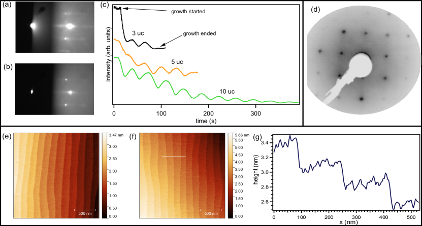
The TiO2 terminated substrates possess large flat terraces with unit cell high steps as can be inferred from the atomic force microscope image in Fig. S1(e). Another indicator for the high quality of the LTO films is, that their surfaces are barely discernible from the substrate in AFM, as demonstrated in the image of a 5 u.c. film with line profile in Fig. S1(f,g).
By in-situ transfer to a photoemission chamber the electronic state of the samples is independently investigated. Using ultra violet light (h eV) we probe the valence band region as can be seen in Fig. S2(a) for a 3 u.c. LTO sample. At the Fermi energy a quasiparticle peak and just 1.1 eV below it the lower Hubbard band are observed. The observation of the former in particular indicates metallic behavior. Due to the very limited inelastic mean free path of the photoelectrons at this excitation energy (approximately 0.1 nm according to Tanuma et al. [60]), we can conclude, that the LTO film itself in addition to the interface [61] is metallic. The most likely explanation for that appears to be excess oxygen p-doping [39].
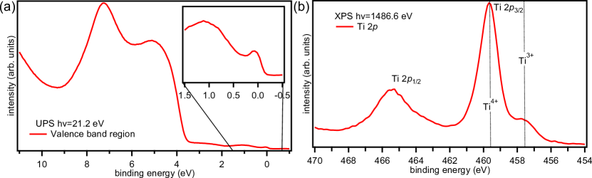
To check this hypothesis we analyze the Ti 2p core level by x-ray photoemission spectroscopy with monochromatized Al-Kα radiation (h=1487 eV). As can be seen in Fig. S2(b) for the same 3 uc LTO sample from above, the spectra is dominated by the Ti4+ valency, indicating a trivial insulating Ti 3d0 configuration. Nonetheless significant Ti3+ spectral weight, chemically shifted to lower binding energies is observed, which we would expect for stoichiometric LTO. The coexistence of both valencies confirms the suspicion that the LaTiO3 is grown overoxidized as LaTiO3+x. To determine the is not easy, as the SrTiO3 substrate also contributes a non-negligible Ti4+ signal and in the not unlikely scenario of oxygen vacancies in the substrate also a small Ti3+ signal to the spectra.
II Sondheimer Oscillations
In 3u.c. thick LTO/STO samples, low-field oscillations were systematically observed (see Fig. S3(a)). Due to their small amplitude, those oscillations are more visible in the second derivative of the resistance (see Fig. S3(b)). These oscillations are visible at low field, starting from zero field on. Their amplitude is damped with increasing magnetic field, and the oscillations finally disappear above about 4T. The amplitude also decreases in amplitude while temperature is increased, and completely vanishes above about 13K.
The fact that the oscillations exist only at low field and are damped with magnetic field is at odds with that of Shubnikov-de-Haas oscillations, which are often observed in high-mobility thin films but would appear starting from a finite field and increase in amplitude with increasing field. Moreover, the peak position increases linearly with magnetic field, as shown in see Fig. S3(c), with a periodicity of T. This further discounts a Shubnikov-de-Haas origin of these low-field oscillations, which would be periodic in inverse magnetic field.
A possible explanation for those oscillations are the so-called Sondheimer oscillations. They are semi-classical oscillations that are due to a resonance condition between cyclotron radius and thickness of the thin film . When applying a transverse magnetic field to a metallic thin-film, electrons undergo cyclotron orbits in plane, which added to the out-of-plane velocity creates a helical motion. If the mean free path is larger than the film thickness, full helical motion can occur within the film thickness without scattering. The number of cyclotron revolution of the trajectory in the thickness is , with the time to propagate in the film thickness from one interface to the other ( is the velocity in the out-of-plane direction); and the time to close a cyclotron orbit in-plane ( is the cyclotron pulsation). When n is an integer, no net in-plane motion is made while propagating in the thickness. However, when n is non-integer, the helix trajectory is interrupted at the film interface, resulting in a net in-plane motion. As Sondheimer showed, this results in an oscillatory behavior of the resistance with magnetic field, where oscillations occur with period [62, 63, 64]. Here corresponds to the derivative of the cross-section of the Fermi surface with out-of-plane momentum .
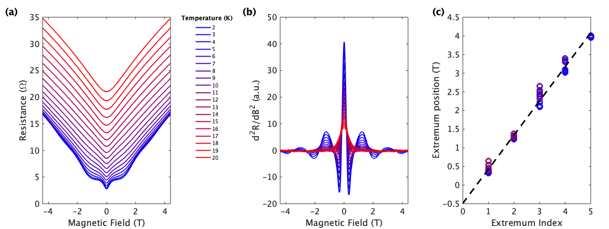
The fact that the observed oscillations are periodic in B, along with the fact that the first oscillation occurs at a smaller field than the 1T periodicity (see Fig. S3(c)), is compatible with the Sondheimer explanation [62]. The extraction of further information about the electronic structure of the film would however require additional information about the band structure and effective mass of the charge carriers, which are unavailable due to the absence of Shubnikov-de-Haas oscillations.
III Temperature and field dependence of the linear magnetoresistance
In order to determine the onset field of the linear magnetoresistance, we plotted the magnetoresistance in a log-log scale in Fig. S4. The linear slope in the log-log plot correspond to the linear MR behavior. An estimate of the critical field at which magnetoresistance becomes linear is defined as the intersect between linear fit and zero-field value. We observe that the critical field decreases with increasing thickness. At low temperature, for the 3u.c. sample, this field is close to 1T, while it decrease in the 5u.c. sample to 500mT, and to less than 200mT for the 10u.c. sample (see Fig. S4).
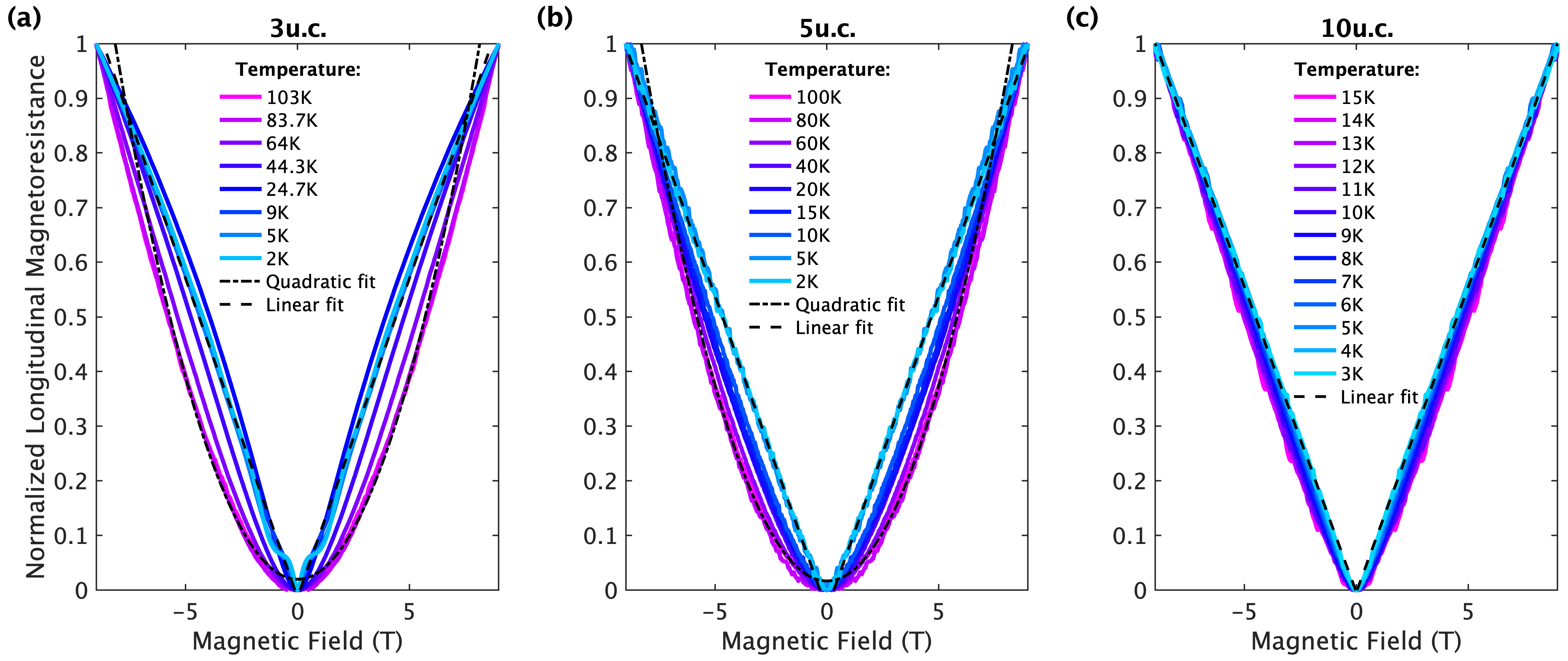
The linear magnetoresistance studied in the main text is a low-temperature effect. To illustrate this, we plotted in Fig. S5 the normalized magnetoresistance
This allows one to observe the transition from a very linear behavior to a parabolic-like behavior. This transition is evidenced in Fig. S5 by the linear fit at low temperature (dashed line) and the parabolic fits at high temperature (dotted line). For the 3u.c. sample, the transition between both regimes accelerates above 30-40K, which corresponds to the temperature at which the magnetic stripe pattern observed in cryogenic TEM starts to vanish. For the 10u.c. sample, the magnetoresistance remains linear up to the maximum temperature of 15K.
IV Lorentz TEM imaging
In this supplement, we supply images of the uniaxial modulation acquired at different foci (Fig. S6). They illustrate the fact that the modulation contrast vanished in focus and changes sign going from under- to overfocus, which proves that the observed contrast is a phase contrast (i.e., stems from a phase modulation of the complex electron wave only). Such a modulation typically indicate magnetic textures in the sample. An electric origin (e.g., ferroelectric domains) is ruled out in this case due to the strong magnetic field dependence of the modulation. The small dark dots distributed across the entire field of view may be associated to impurities, or point defects. They are deformed to asterisks due to induced astigmatism caused by the applied external magnetic field.
Note, however, that the small film thickness of the LTO shifts the phase modulation below observability threshold in standard kinematic scattering conditions employed in Lorentz TEM. Typical Lorentz TEM observations of such modulations require magnetic film thickness of several tens of nanometer. As mentioned in the main text, to reveal the magnetic stripes in our thin films we exploit the enhanced sensitivity of dynamic scattering conditions (i.e., scattering beyond first order Born approximation valid close to locally fulfilled Bragg conditions for electron diffraction) towards small phase shift (equivalent to scattering direction) modulations of the electron beam [65] imprinted by magnetic fields in the thin \chLaTiO3 film (Fig. 3(a) of the main text). Close to Bragg conditions, where scattering into systematic diffraction directions is strongly enhanced and dynamical scattering sets in (exemplified by the loss of intensity in bending contours of non-diffracted beam), small phase (and corresponding beam direction) modulations can be magnified by more than one order of magnitude depending on the excitation error (i.e., deviation from exact Bragg condition) and other parameters like the thickness of the sample. This is sufficient to amplify the small magnetic phase modulation of the thin LTO film in our case. These are then visualized under strong defocus (LTEM imaging conditions).

Lastly, we provide in Fig. S7 another example of uniaxial stripe modulations at bending contours, which exhibit two perpendicular modulation directions aligned with the crystallographic orientations of the underlying SrTiO3 substrate in one field of view.

V Theoretical modeling
V.1 Magnetism in the \chLaTiO3 heterostructure
Experimental [52] and theoretical [53] investigations established that bulk LaTiO3 orders antiferromagnetically (AF) at low temperature with canted Ti3+ moments, resulting in a small ferromagnetic component. The structure is shown in Fig. S8, where refers to the orthorhombic basis vectors. is the angle of the magnetic moments with respect to the plane and denotes the absolute value of the angle between the projection of the moments onto the plane and the axis. The canted AF ordering is caused by Dzyaloshinskii-Moriya (DM) and exchange asymmetry terms allowed by symmetry. Doping the system with holes leads to a percolative-style decrease in the magnitude of the zero temperature average moment as observed in experiments on LaTiO3+δ samples with [52]. At low temperature, a metal-to-insulator transition occurs at a critical doping such that the material is insulating for , while it hosts coexisting metallic and magnetic states for . The off-stoichiometry oxygen holes dope the Ti ions turning a fraction of them into Ti4+. This causes site dilution of the magnetic Ti3+ moments and also produces metallic puddles. When puddles merge to form a percolative metallic phase [66]. When a homogeneous metallic and paramagnetic state is obtained.
The LTO/STO heterostructure is polar and in order to mitigate the electrostatic energy build-up [67] an electron liquid is produced in the material. If we consider that the negative charges originate from the Ti3+ ions on the LTO side, we may transpose the previous considerations to the interface case. We note that, in contrast to the LaAlO3/SrTiO3 case, metallicity is expected to concern both sides of the interface. If the uniaxial modulations observed in TEM are caused by a spiral magnetic structure, as we argue in the main text, we conclude that in our experiments, the electron fraction donated by each Ti3+ site of LTO in the heterostructure is such that . In the percolative metallic phase, the volume fractions of the metal and of the insulator satisfy and (Maxwell construction in a two-phase state). At the percolation threshold , which is close to the critical occupation for the square lattice site percolation problem. The very low value of the resistivity of the 10 u.c. samples suggests a proximity to the homogeneous phase and a sizable carrier concentration, so we estimate , i.e %.

In the effective Hamiltonian (equation (2) of the main text), the anisotropy tensor has non-zero elements in the plane of the interface. Due to the tilt and rotation of the TiO6 octahedra in LTO, hopping amplitudes are given by a non-diagonal matrix[53] such that the interfacial DM mostly affects .
To see the stability of the spiral state, we checked that the demagnetizing energy due to the small ferromagnetic component at the boundaries [54] does not alter the spiral magnetic ground state. The stability of the spiral, when a magnetic field is applied perpendicularly to the interface, depends on the strength of the in-plane DM of LTO and of the exchange asymmetry. Using values listed in Ref (53), with a typical anisotropy parameter meV, we estimate that moments align along when the magnetic field exceeds T, which is above the maximum field available in our magnetotransport measurements.
V.2 Mobility in the spin spiral domains
As can be seen in Fig. 3 of the main text, the linear scale of the magnetic modulation region is on the order of a micrometer. According to the scenario that we advocated to explain its origin, this suggests that the spin diffusion length, , has a similar magnitude. As electrons move through the stripe pattern, they experience spin scattering due to the change in the direction of alignment of the local moments, perpendicularly to the stripe. Following [68], we determine the transmission and reflection coefficients a la Landauer-Büttiker, for electrons traveling across a structure consisting of two antiferromagnetically ordered regions separated by a paramagnetic spacer layer. The direction of the alignment in the second region is at an angle with respect to that in the first region. The system is equivalent to a Fabry-Pérot interferometer, so that we model one period of the spin spiral pattern as interferometers in series ( nm, ). A priori one should include two main types of processes. In the direct process, a portion of the wave hits interferometer and is subsequently transmitted to . In the indirect process, the portion of the wave that is reflected from interferometer , travels in the backward direction towards interferometer , where part of it is reflected and then moves in the forward direction towards interferometer where it adds its contribution to the transmitted portion of the initial wave; the amplitude of this indirect process is at most , which decreases exponentially with ; in addition it contains a phase factor, which stems from the distance involved in the indirect process, producing a phase difference between the two amplitudes. Overall, we neglect these secondary processes, which introduce small corrections to and . For , [68] and over a distance m, there are interferometers. The ratio of the mobility in the presence of the spin spiral over the mobility in its absence is . Consequently the mobility in the stripe region is at least one order of magnitude smaller than in the rest of the sample.