Reflection Channel Model for Terahertz Communications
††thanks: This work was funded by the NSF under grant CNS-1910655.
††thanks: All our data and code is available at: http://web.cecs.pdx.edu/ singh/projects/thzmimo/Home.html
Abstract
Terahertz frequencies are an untapped resource for providing high-speed short-range communications. As a result, it is of interest to study the propagation characteristics of terahertz waves and to develop channel models. In previous work we used a measurement-based approach to develop an accurate channel model for line of sight (LoS) links. In this paper we extend that work by developing channel models for non-line of sight (NLoS) links where the signal suffers one reflection. We study reflections that occur off a metal plate as well as a piece of wood.
Our model for received magnitude includes the effects of standing waves that develop between the transmitter and receiver. Measurements show an excellent agreement between empirical data and the model. In addition, we have analyzed the received phase of the reflected signal at frequencies in the range 320-480 GHz. We observed a linear error between the predicted and actual phase and developed a model to accommodate that discrepancy. The final model we have developed for predicting received phase is very accurate for the entire range 320 - 480 GHz and for both materials.
Index Terms:
Terahertz, channel model, reflectionI Introduction
The terahertz frequency band, which extends from 100 GHz to 3 THz is being studied for the next generation of wireless communication systems [1, 2]. Expected applications include ultra high data rate short-range communication (e.g., device to device or chip-to-chip), as an alternative to free-space optics, and as a wifi-like system for small offices etc. There are many challenges in deploying terahertz communication systems including its high attenuation with distance as well as with reflections and frequency-specific molecular absorption. Among the frequencies available, channels at 140, 220, 340, 410, and 460 GHz have been identified as viable communication channels as they suffer the least (though still considerable) environmental attenuation [3]. Thus, several different research efforts have been directed at developing communication systems at these bands. Examples of work most related to ours include prototype communication systems as proof of concept [4, 5, 6, 7], and channel models for line of sight (LoS) communication [8, 9, 10, 1, 11]. Our work has been on using measurements to develop channel models for LoS channels and MIMO LoS channels [11, 12, 13, 14]. In this paper we extend the channel model for the case of terahertz reflections off metallic and wooden surfaces. The channel model shows good agreement with measurements for both cases.
The usage scenario for terahertz reflections is best explained by considering an office with a ceiling mounted THz access point. Because terahertz channels are primarily LoS, carefully planned reflections are needed in order to provide full coverage in these scenarios. For instance, due to environmental clutter such as furniture, direct LoS paths between the access point and a user may be blocked. Thus, to reach the user, a reflection off a ceiling mounted metal plate could be used. These types of surfaces are called passive reflective surfaces (as opposed to active reflective surfaces) and are inexpensive to use. Similarly, if there is a sufficient density of such reflective surfaces, we can envision multiple reflected paths existing between the AP and user which would allow us to provide a high data rate channel. Our measurements show that reflections off metal and wood provide a viable alternative signal path. Of course, as expected, reflections off wood are suffer much greater attenuation (approximately 10dB greater path loss as compared to metal).
The remainder of the paper is organized as follows:
II Related Work
There has been considerable work on developing channel models for terahertz frequencies over the past few years such as ray tracing [15, 16, 17], empirical fitting using free-space models [18, 19, 20] and others [21, 22, 23, 24, 25, 26]. These models typically have to account for the specific impairments suffered by terahertz radiation such as high path loss [27], atmospheric absorption [20], reflection from indoor building material [28, 29], time dispersion [30], and RF impairments [31]. Other papers have reported on measurements and modeling for specific use scenarios. For instance, [20] reports on long range (110m) terahertz links upto 1 THz, [22, 24] studies LoS and NLoS channels around vehicles, or train-to-infrastructure [23], rack-to-rack and blade-to-blade communication in data centers [26], and device-to-device communication [15].
In our previous work, we have used both a time-domain system (with HDPE lenses) as well as a VNA system to measure and subsequently characterize the channel [13, 14, 12]. More recently, we observed that at specific distances the received power increases as compared with somewhat shorter distances. This observation led us to the discovery that standing waves produced between the transmit and receive antenna are responsible for the behavior [11].
In this paper we extend our prior work to consider single reflections. There has been work done on terahertz reflections such as vehicle reflections [24], indoor materials including drywall, clear glass as well as stratified building materials [29, 32, 28], and different metal materials [32]. However, most of the work doesn’t consider the effect of standing waves which is considerable in short-range communication. Our work in this paper will provide a more complete model that incorporates the effects of the standing wave and that predicts phase accurately.
III Measurement Setup and Experimental Design
A typical indoor signal path for sub-mmwave frequencies between transmitter and receiver is characterized by a line of sight path as well as numerous reflected paths which enables good coverage. At terahertz frequencies, on the other hand, most non-line of sight paths are absent due to air and material attenuation or direct blockage by obstacles. Thus, our goal is to determine if reflected paths can be created at these frequencies to enhance indoor coverage. Metals are ideally suited to this task because reflections are barely attenuated and indeed they act as mirrors at terahertz. We envision having metal sheets embedded in the ceiling of rooms to create a path between terahertz access points and devices that are not in the line of sight of the AP. Our goal in this paper is to precisely characterize such a reflected channel.
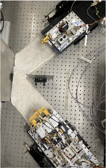
The measurement setup is illustrated in Figure 1 in which an aluminium plate is used to provide a NLoS signal path. To ensure that there is no additional reflection path other than from the aluminium plate, wet towels are placed under the propagation path. We have previously shown that the inclusion of this wet towel eliminates the reflection from the optical table [11]. Another small aluminum piece is put in between the Tx and Rx to block any direct signals. An identical setup is used with wooden boards to characterize reflections off wood.
To conduct the experiments, we use a Rohde & Schwartz Vector Network Analyzer (VNA) and Virginia Diodes, Inc. (VDI) frequency extender modules. The WR2.2 band extender module is capable of generating signals from 325 GHz to 500 GHz. Before measurement, the system is calibrated using Thru-Reflect-Line (TRL) standards. This calibration moves the measurement reference plane to the waveguide opening. Other VNA settings are listed in Table I. For this band, horn antennas with 25dB gain are used to transmit and receive signals. The length of these antennas is 1.68 cm.
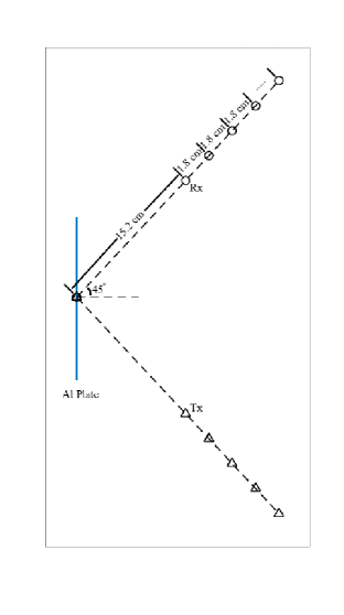
In this paper, we explore the case of incident angle. The minimum distance between the Tx/Rx to the Aluminium plate is 15.2 cm. For each measurement, both Tx and Rx are moved 1.8 cm further away from the Aluminium plate. Figure 2 shows the detailed diagram of the measurement setup with a total of 12 distances. Note that all distances are measured from one antenna’s aperture to the other’s.
| Output power | 5 dBm |
|---|---|
| Frequency range | 325 - 500 GHz |
| Frequency step | 0.1 GHz |
| IF Bandwidth | 1 kHz |
| Averaging | 10 |
| Calibration | Thru-Reflect-Line |
IV Channel Model
For magnitude path loss fitting, we use the channel model from the previous work [11]. In this model, the standing wave effect between the transmit and receive horn antennas is taken into account to modify the single-frequency floating intercept model which has the path loss (PL) written as equation (1).
| (1) |
where is the distance, cm is the minimum distance, is a floating intercept in dB that denotes the free-space path loss at , is the distance-based path loss exponent, and is the large-scale shadow fading that is modeled as a zero-mean Gaussian with standard deviation .
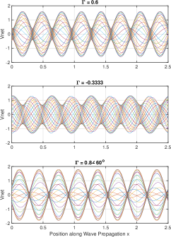
Equation (2) shows the magnitude of the standing wave with as the wavenumber, and as the reflection coefficient. is complex amplitude corresponding to the forward wave at .
| (2) |
Figure 3 illustrates the effect of reflection coefficient , wavelength on the standing wave.
IV-A Parameter Estimation for Magnitude
We first fit the measured data into equation (1) to estimate the parameters and using the least squares linear fit such that the root mean square deviation from the mean path loss is minimized. The difference between the fit and measured data is used to obtain the initial guess values for and . Since the standing wave is added into the received signal, it is then subtracted (in dB) from the from the path loss formula in equation 1 to obtain the final model. The least squares linear fit is repeated with and as optimizing variables to provide more accurate fit with smaller root mean square value compared to fitting solely the single-frequency floating intercept model.
IV-B Parameter Estimation for Phase
The phase shift according to frequency change is shown in equation (3)
| (3) |
where is the phase shift (rad), d is the distance, c is the speed of light, and is the change in frequency.
First, we apply the linear fit to a small range of frequency around the interested frequency to obtain the fitted distance from the slope of the measured data. Figure 4 shows the fitting for 340 GHz center frequency at d = 52 cm. The phase response is a straight linear line shows that the system is correctly calibrated. However, the distance calculated from the slope is 57.55 cm. This is different from the measured distance of 52 cm even if we add 1.68cm x 2 (two times the antennas length). The other fitted distances at 340 GHz are listed in Table II.
| dmeas | 340 GHz | 480 GHz | ||
|---|---|---|---|---|
| dfit | dfit | |||
| 30.40 | 35.90 | 5.50 | 33.92 | 3.52 |
| 34.00 | 39.50 | 5.50 | 37.49 | 3.49 |
| 37.60 | 43.28 | 5.68 | 41.24 | 3.64 |
| 41.20 | 46.67 | 5.47 | 44.52 | 3.32 |
| 44.80 | 50.34 | 5.54 | 48.07 | 3.27 |
| 48.40 | 53.62 | 5.22 | 51.64 | 3.24 |
| 52.00 | 57.55 | 5.55 | 55.50 | 3.50 |
| 55.60 | 61.02 | 5.42 | 58.81 | 3.21 |
| 59.20 | 64.62 | 5.42 | 62.45 | 3.25 |
| 62.80 | 68.26 | 5.46 | 66.27 | 3.47 |
| 66.40 | 72.02 | 5.62 | 69.90 | 3.50 |
| 70.00 | 75.26 | 5.26 | 73.37 | 3.37 |
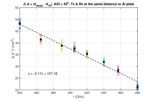
To examine this discrepancy between measured distance and fitted distance, we apply the same linear fit for the rest of the distances and center frequencies (410, 460 GHz). We observe that the difference between measured and fitted distance remains constant for a given frequency. Furthermore, the product of the difference in distance and the wavelength yields a linear function vs frequency as shown in Figure 5. The linear equation from Figure 5 can be used to predict the error in distance for a given frequency.
| (4) |
where is the difference between measured and fitted data, is wavelength and is frequency.
Equation 4 can thus be used for phase prediction for a given frequency and distance. The algorithm to do this is:

V Measurements and Validation
We conducted measurements for three frequencies: 340, 410, and 460 GHz. For each, we took multiple measurements at 12 distances (total path length from the Tx to metal/wood plate to Rx). Figures 6,7,8 plot the attenuation of the received signals against distance for each case. Observe that the dots (which are the measured data) show increasing attenuation with distance, as expected, but also a reduction in attenuation for some distances. This is caused by standing waves that get established between the Tx and Rx, as we described in [11]. It is noteworthy that the standing wave exists even when the signal is reflected. The next next two sections we describe our fit for amplitude and phase.
V-A Magnitude fitting
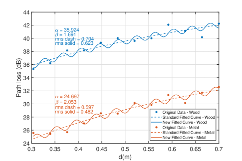
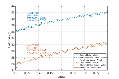
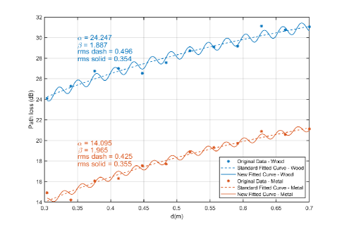
The path loss fitting of frequencies 340 GHz, 410 GHz, 460 GHz for both metal plate and wooden board as reflection surface are illustrated in Figures 6,7,8. As expected, the fitting with the standing wave effect give an improved agreement with the measured data. Overall, the path loss in the metal plate case is around 10dB lower than the measurements with the wooden board. The root mean square values are reasonable compared to the line of sight path loss cases in [11].
The reflection coefficient and wavenumber from the fitting is listed in Table III. The standing wave phenomena still holds in this NLoS case as metal acts as an almost perfect reflector as this frequency range [33].
| 340 GHz | 410 GHz | 460 GHz | |
| Metal Plate | |||
| k | |||
| Wood Plate | |||
| k | |||
We observe that the reflection coefficient for the standing wave is slightly different when comparing the LoS case from [11] as opposed to the NLoS case studied in this paper, Table IV. This is because reflections from the metal plate affects the overall measured value for . Thus, we have multiple standing waves established between Tx-plate, Tx-plate-Rx, plate-Rx, Tx-plate-Rx-plate-Rx, and some others. The value reported in Table IV is the cumulative effect of all these standing waves. Observe that the presence of these also affect the measured phase. However, since the amplitude is relatively small, these cause only a small phase error.
| LoS | NLoS | |
|---|---|---|
| 340 | 0.05 | 0.06 |
| 410 | 0.09 | 0.06 |
| 460 | 0.06 | 0.04 |
V-B Phase fitting
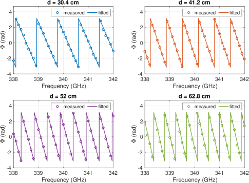
We use the algorithm outlined in section IV-B to fit the phase for each of the three center frequencies. For each frequency, we first compute (distance between measured and fitted distance) and correct the measured distance by adding . This fitting yields:
| (5) |
This corrected distance is then used to compute the phase from equation 3. Phase around the center frequency 340 GHz at distances of 30.4, 41.2, 52, 62.8 cm is plotted in Figure 9. We obtain an excellent match between the measured and predicted phases. Other measurements around 410 GHz, 460 GHz also gives the same quality match. The measurements using wooden board for these frequencies show a similar linear relationship to (5) with slope of -0.18 and offset of 106.68. We obtain very good agreement between the fitted and measured phase data.
VI Conclusion
In this paper, a complete channel model is obtained and verified for the case of a single reflection for terahertz when the reflection is off a metal plate and a wooden board. The amplitude fit, with the inclusion of standing wave, is much better compared to the standard single frequency floating intercept model. We have also provided an algorithm for computing the parameters of the fit for the magnitude.
In addition, we have developed a model to predict the phase of the received signal after a single reflection. We observed that for each frequency, there is a constant discrepancy between the actual Tx-wall-Rx distance and the distance predicted by using the arriving phase. We observe that this discrepancy in predicted vs actual distance has a linear relationship to frequency. Using this observation, we have developed an algorithm to correct the predicted phase at the receiver and we show that our model provides a phase that is very close to actual measured phase.
In current and future work we are extending the model to reflections from other materials typically used in indoor spaces. In addition, we are developing models for multiple reflections for frequencies upto 520 GHz.
References
- [1] I. A. Hemadeh, K. Satyanarayana, M. El-Hajjar, and L. Hanzo. Millimeter-wave communications: Physical channel models, design considerations, antenna constructions, and link budgets. IEEE Communications Surveys & Tutorials, 20(2):870 – 913, 2018.
- [2] Y. Xing, O. Kanhere, S. Ju, and T. S. Rappaport. Indoor wireless channel properties at millimeter wave and sub-terahertz frequencies. In Proceedings IEEE GLOBECOM 2019, pages 1 – 6, December 2019.
- [3] John Federici and Lothat Moeller. Review of terahertz and subterahertz wireless communications. Journal of Applied Physics, 107, 2010.
- [4] Ingmar Kallfass, Jochen Antes, Thomas Schneider, Fabian Kurz, Daniel Lopez-Diaz, Sebastian Diebold, Hermann Massler, Arnulf Leuther, and Axel Tessmann. All active MMIC-based wireless communication at 220 GHz. IEEE Transactions on Terahertz Science and Technology, 1(2):477–487, November 2011.
- [5] A. Hirata, T. Kosugi, H. Takahashi, J. Takeuchi, K. Murata, N Kukutsu, Y. Kado, S. Okabe, T. Ikeda, F. Suginosita, et al. 5.8-km 10-Gbps data transmission over a 120-GHz-band wireless link. In 2010 IEEE International Conference on Wireless Information Technology and Systems (ICWITS),, pages 1–4. IEEE, 2010.
- [6] S. Koenig, D. Lopez-Diaz, J. Antes, F. Boes, R. Henneberger, A. Leuther, A. Tessmann, R. Schmogrow, D. Hillerkuss, R. Palmer, T. Zwick, C. Koos, W. Freude, O. Ambacher, J. Leuthold, and I. Kallfass. Wireless sub-THz communication system with high data rate. Nature Photonics, 7:977–981, October 2013.
- [7] H.J. Song, K. Ajito, Y. Muramoto, and A. Wakatasuki. 24 Gbit/s data transmission in 300 GHz band for future terahertz communications. Electronics Letters, 48(15):953–954, July 2012.
- [8] S. Kim and A. Zajic. Statistical modeling and simulation of short-range device-to-device communications channel at sub-thz frequencies. pages 6423–6433, September 2016.
- [9] C. Han, A. O. Bicen, and I. F. Akyilidiz. Multi-ray channel modeling and wideband characterization for wireless communications in the thz band. IEEE Transactions on Wireless Communications, 14(5):2402 – 2412, May 2015.
- [10] A. Saleh and R. Valenzuela. A statistical model for indoor multipath propagation. IEEE Journal on Selected Areas in Communications, 5(2):128 – 137, May 1987.
- [11] Ha Tran, Thanh Le, and Suresh Singh. Effect of Standing Wave on Terahertz Channel Model. In 2021 IEEE International Conference on Communications Workshops (ICC Workshops), pages 1–6, June 2021.
- [12] Farnoosh Moshir and Suresh Singh. Modulation and rate adaptation algorithms for terahertz channels. Nano Communication Networks, 10:38–50, December 2016.
- [13] Suresh Singh, Ha Tran, and Thanh Le. Challenges in LoS Terahertz MIMO. In 2019 IEEE Global Communications Conference (GLOBECOM), pages 1–5, December 2019.
- [14] Suresh Singh, Thanh Le, and Ha Tran. Measurement of 2x2 LoS Terahertz MIMO Channel. In 2020 IEEE Wireless Communications and Networking Conference (WCNC), pages 1–5, May 2020.
- [15] Thomas Kürner, Alexander Fricke, Sebastian Rey, Philippe Le Bars, Achir Mounir, and Thomas Kleine-Ostmann. Measurements and Modeling of Basic Propagation Characteristics for Intra-Device Communications at 60 GHz and 300 GHz. Journal of Infrared, Millimeter, and Terahertz Waves, 36(2):144–158, February 2015.
- [16] Chong Han, A. Ozan Bicen, and Ian F. Akyildiz. Multi-Ray Channel Modeling and Wideband Characterization for Wireless Communications in the Terahertz Band. IEEE Transactions on Wireless Communications, 14(5):2402–2412, May 2015.
- [17] Gregory Gougeon, Yoann Corre, and Mohammed Zahid Aslam. Ray-based Deterministic Channel Modelling for sub-THz Band. In 2019 IEEE 30th International Symposium on Personal, Indoor and Mobile Radio Communications (PIMRC Workshops), pages 1–6, September 2019.
- [18] Shu Sun, Theodore S. Rappaport, Mansoor Shafi, Pan Tang, Jianhua Zhang, and Peter J. Smith. Propagation Models and Performance Evaluation for 5G Millimeter-Wave Bands. IEEE Transactions on Vehicular Technology, 67(9):8422–8439, September 2018.
- [19] Shu Sun, Theodore S. Rappaport, Timothy A. Thomas, Amitava Ghosh, Huan C. Nguyen, István Z. Kovács, Ignacio Rodriguez, Ozge Koymen, and Andrzej Partyka. Investigation of Prediction Accuracy, Sensitivity, and Parameter Stability of Large-Scale Propagation Path Loss Models for 5G Wireless Communications. IEEE Transactions on Vehicular Technology, 65(5):2843–2860, May 2016.
- [20] Sam Razavian, Mostafa Hosseini, Yash Mehta, and Aydin Babakhani. Terahertz Channel Characterization Using a Broadband Frequency Comb Radiator in 130-Nm SiGe BiCMOS. IEEE Transactions on Terahertz Science and Technology, 11(3):269–276, May 2021.
- [21] Shihao Ju, Yunchou Xing, Ojas Kanhere, and Theodore S. Rappaport. Millimeter Wave and Sub-Terahertz Spatial Statistical Channel Model for an Indoor Office Building. IEEE Journal on Selected Areas in Communications, 39(6):1561–1575, June 2021.
- [22] Atsushi Yamamoto, Koichi Ogawa, Tetsuo Horimatsu, Akihito Kato, and Masayuki Fujise. Path-Loss Prediction Models for Intervehicle Communication at 60 GHz. IEEE Transactions on Vehicular Technology, 57(1):65–78, January 2008.
- [23] Ke Guan, Bile Peng, Danping He, Johannes M. Eckhardt, Sebastian Rey, Bo Ai, Zhangdui Zhong, and Thomas Kürner. Measurement, Simulation, and Characterization of Train-to-Infrastructure Inside-Station Channel at the Terahertz Band. IEEE Transactions on Terahertz Science and Technology, 9(3):291–306, May 2019.
- [24] Johannes M. Eckhardt, Vitaly Petrov, Dmitri Moltchanov, Yevgeni Koucheryavy, and Thomas Kürner. Channel Measurements and Modeling for Low-Terahertz Band Vehicular Communications. IEEE Journal on Selected Areas in Communications, 39(6):1590–1603, June 2021.
- [25] Josep Miquel Jornet and Ian F. Akyildiz. Channel Modeling and Capacity Analysis for Electromagnetic Wireless Nanonetworks in the Terahertz Band. IEEE Transactions on Wireless Communications, 10(10):3211–3221, October 2011.
- [26] Chia-Lin Cheng and Alenka Zajić. Characterization of Propagation Phenomena Relevant for 300 GHz Wireless Data Center Links. IEEE Transactions on Antennas and Propagation, 68(2):1074–1087, February 2020.
- [27] Yunchou Xing and Theodore S. Rappaport. Propagation Measurement System and Approach at 140 GHz-Moving to 6G and Above 100 GHz. In 2018 IEEE Global Communications Conference (GLOBECOM), pages 1–6, December 2018.
- [28] Christian Jansen, Radoslaw Piesiewicz, Daniel Mittleman, Thomas Kurner, and Martin Koch. The Impact of Reflections From Stratified Building Materials on the Wave Propagation in Future Indoor Terahertz Communication Systems. IEEE Transactions on Antennas and Propagation, 56(5):1413–1419, May 2008.
- [29] Yunchou Xing, Ojas Kanhere, Shihao Ju, and Theodore S. Rappaport. Indoor Wireless Channel Properties at Millimeter Wave and Sub-Terahertz Frequencies. In 2019 IEEE Global Communications Conference (GLOBECOM), pages 1–6, December 2019.
- [30] Sijia Deng, Mathew K. Samimi, and Theodore S. Rappaport. 28 GHz and 73 GHz millimeter-wave indoor propagation measurements and path loss models. In 2015 IEEE International Conference on Communication Workshop (ICCW), pages 1244–1250, June 2015.
- [31] Nizar Bouhlel, Majed Saad, and Faouzi Bader. Sub-Terahertz Wireless System Using Dual-Polarized Generalized Spatial Modulation With RF Impairments. IEEE Journal on Selected Areas in Communications, 39(6):1636–1650, June 2021.
- [32] Jianjun Ma, Rabi Shrestha, Lothar Moeller, and Daniel M. Mittleman. Invited Article: Channel performance for indoor and outdoor terahertz wireless links. APL Photonics, 3(5):051601, May 2018.
- [33] Mira Naftaly and Richard Dudley. Terahertz reflectivities of metal-coated mirrors. Applied Optics, 50(19):3201–3204, July 2011.