Smart windows passively driven by greenhouse effect
Abstract
The rational thermal management of buildings is of major importance for the reduction of the overall primary energy consumption. Smart windows are promising systems which could save a significant part of this energy. Here we introduce a double glazing system made with a thermochromic metal-insulator transition material and a glass layer separated by an air gap which is able to switch from its insulating to its conducting phase thanks to the greenhouse effect occuring in the separation gap. We also show that this passive system can reduce the incoming heat flux by in comparison with a traditional double glazing while maintaining the transmittance around over of visible spectrum.
Nowadays buildings consume about of the primary energy used in the world Ramesh . Therefore their thermal management is a major concern in the context of current global challenge of energy efficiency. Smart windows could play a major role to respond to this challenge. These windows can be used to control heat flux exchanged between the indoor and external environnment. One way to achieve this control is by tuning the radiative properties of these systems. Hence, by controlling the overall emissivity/transmittivity of a window surface it is possible to facilitate or reduce heat exchange with the environment and therefore to act directly on the indoor temperature. Several strategies have been proposed so far to perform such a control. For example, single glazings made of thermochromic materials have been suggested Kim ; Zheng ; Chang to tailor the optical properties of windows with respect to their temperature. Among these materials vanadium dioxide (VO2) a metal-insulator transition (MIT) material has been largely investigated. Due to their pronounced change of optical properties in the infrared these phase-change materials have found numerous applications in the fields of thermal management pba2013 ; pba2014 ; pba2014_bis ; Reddy2018 ; Kats , energy storage Kubytskyi and information treatment pba2016 . However this material undergoes a reversible structural phase transition at relatively high temperature (C) making its employment challenging in smart windows. Moreover, to date, there is no real alternative candidate to this material presenting a pronounced MIT close to the ambient temperature. Electrochromic materials have also been proposed Cannavale ; Chen to modify the optical properties of smart windows using an external bias voltage. Hence, by using VO2 solid-electrolyte films, the light transmittance of such gate-controlled smart windows can be dramatically modified by tuning the hydrogen-ion doping through gating voltage. However, although this optical control can operate at ambient temperature it requires an external energy supply. Moreover, electrochromic windows are mainly effective in blocking visible light and not infrared radiation so that their thermal performances remain today very weak.
In the present letter we introduce a passive smart window based on a double glazing system (Fig. 1) realized with a VO2 film deposited on the internal side of the glazing. The two panes of this glazing are separated by a few-milimeter thick gap filled with noble gas.
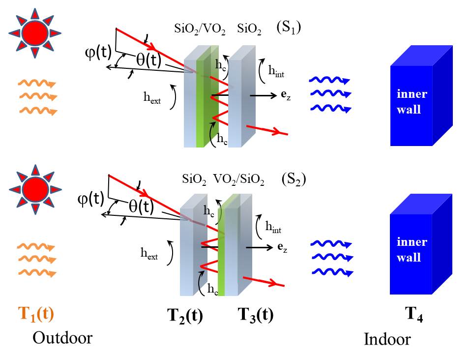
Following the evolution during the day of external conditions of sunshine evolve during the day the temperature of this MIT material changes thanks to the greenhouse effect occuring between the two panes. By optimizing the geometry of this system we show that we can at the same time control its transmittance in the visible range and the incoming heat flux. More specifically, by analyzing the temporal evolution of this thermo-optical system driven by the external sunshine and the heat flux radiated in the infrared by the external environment and the inner walls we show that our smart-window design results in a significant reduction of the heat flux reaching the inner side, compared to traditional windows, in conjunction with a low reduction of the transmittance in the visible range of the spectrum.
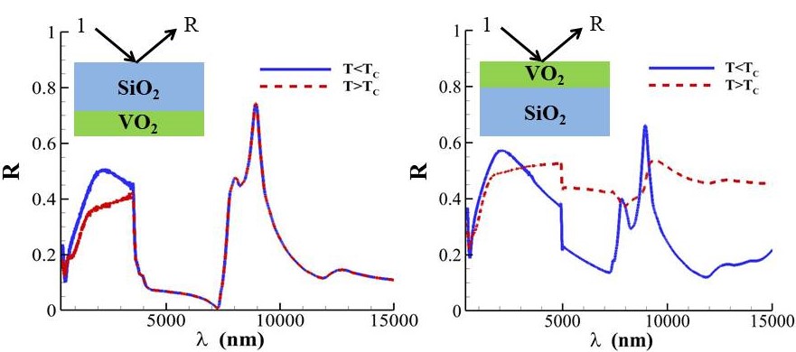
To start let us describe the physical characteristics of system. The active part is made of a vanadium dioxide (VO2) film which undergoes a first-order transition (Mott transition Mott ) from a high-temperature metallic phase to a low-temperature insulating phase Barker ; Barker2 at . This film is deposited on a glass layer which is partially transparent in the infrared range Palik . As a result of the phase transition both the emissivity and the reflectivity of this bilayer change radically (Fig. 2) on its two sides both in the visible and in the infrared. The outside pane of the window is assumed to be in contact with a thermal bath having temperature and is illuminated by the sun with a time-varying flux depending on the sun trajectory during the day. For the sake of simplicity, the field radiated by the bath can be assimilated to the field radiated by a blackbody at the same temperature. On its opposite side the window interacts with the inner walls of average emisssivity at temperature . Due to the thermal inertia of walls, is assumed here constant during a solar cycle.
The optical properties (emissivity/transmittivity) of the window are driven by the temperature of each pane and therefore by the heat flux they exchange between them and with the outdoor and indoor environments. The time evolution of the thermal state of the window under the external driving is governed by the coupled energy-balance equations
| (1) |
Here denotes the total surfacic power received by the element from all other elements of the system, the contribution of solar flux, the losses/gains due to the convective exchanges and the heat capacity per unit surface for the pane of the window. The power exchanged per unit surface by each plate () with its surrounding by convection is calculated from the convective heat transfer coefficients , and (within the cavity formed by the two panes, between the external medium and the external pane and between the inner medium and the internal pane) using the linear Newton’s law of cooling
| (2) |
which takes into account the convective interactions on all sides of the layer. We consider here a double glazing with a cavity filled with a noble gas, such as Argon, and we assume each pane cooled or heated up by natural convection on its opposite side. With vertical windows and temperature differences between the panel and its surrounding smaller than C the corresponding heat transfer coefficients can be reasonably set to WmK-1 and WmK-1 which correspond to the typical values for vertical panels in these conditions Awbi ; McAdams . Hence, the power exchanged by convection between each panel and its surrounding is about that is a third of the solar irradiation. In this preliminary study, we do not include the heat exchanges due to forced convection or turbulent exchanges between each pane and its surrounding environment. These effects as well geometric effects such as the window inclination and sizing will be analyzed in future works. The heat flux across any plane parallel to the interacting surfaces is given by the normal component of Poynting vector
| (3) |
Here denotes the unit vector normal to the panes of windows, and are the local electric and magnetic fields which are generated by the randomly fluctuating source currents in each solid and by the fields radiated by media and while represents the classical statistical averaging over all field realizations. Using the Fourier decomposition of electric and magnetic fields can be recasted in terms of the field correlators of local field amplitudes in polarization RMP ; Latella
| (4) |
where and denote the parallel and normal components of the wavector. The correlators and in each region of the system can be written in term of correlators of fields radiated by each solid and by the external baths. We summarize below the calculation of one of such correlators (say in the windows cavity), the calculation of all others correlators being similar. The right and left propagating fields in this cavity are related to the fields in the region of baths and to the fields () emitted by each pane by the following systems (by omitting to write the polarization for clarity reasons)
| (5) |
where and are the reflection and transmission operators of the layer toward the right () and the left (), respectively. By solving this system with respect to the cavity field we get
| (6) |
where we have set . It follows that the correlators () into the cavity reads in term of correlators of fields radiated by each solid
| (7) |
But, according to the fluctuation dissipation theorem Rytov , these correlators reads
| (8) |
with
| (9) |
and . Finally, the radiative power received by the two panes from the rest of the system (except the sun) reads
| (10) |
being the panes thickness.
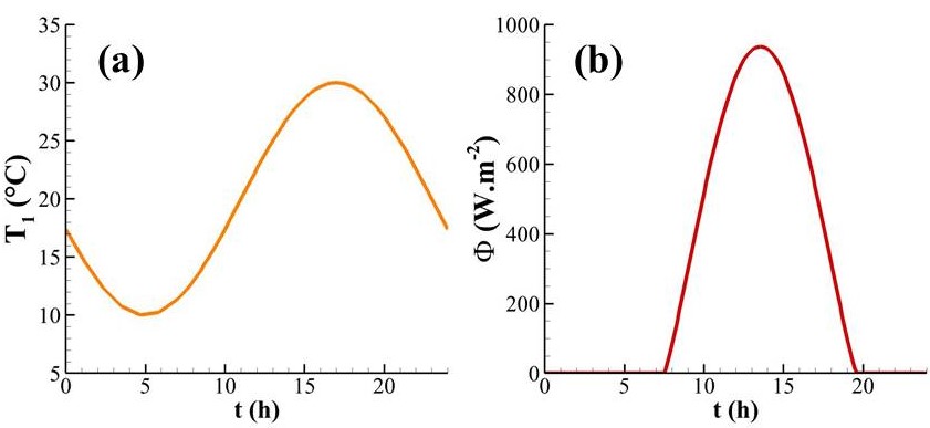
The solar flux plotted in Fig. 3(b) is calculated from the AM1.5 Global spectrum NREL over a daily cycle for a window facing south. We also assume a sinusoidal variation of the outdoor temperature [Fig. 3-(a)] with a minimal value C at a.m. and a maximal value C at at p.m., corresponding to a typical variation of this temperature during summer. Finally, in order to demonstrate the operating mode of the window we assume the inner wall perfectly absorbing (i.e. ). The time evolution of these two primary sources being very slow in comparison with the thermalization time of glazing ( few seconds to the minute), the energy balance Eq. (1) can be solved in the adiabatic approximation.
The solutions of this balance equation corresponding to the external conditions (solar flux , outdoor temperatures ) given the indoor temperature C are plotted in Fig. 4 for different thicknesses of VO2 film and compared to the thermal state of a simple glass-glass double glazing. As shown in Figs. 4(a) and (b) the temperature of the active layer can reach, at the midday, levels significantly higher than the critical temperature . The comparison of (resp. ) with the temperatures of a double (glass-glass) glazing of same thickness demonstrates the presence of a strong greenhouse effect in the designed window due to the trapping of the infrared light in the separation gap between the two panes. The magnitude of this effect is directly related to the thickness of VO2 film. As shown in Figs. 4(a) and (b), the thicker is this film the greater is the blocked infrared radiation in the separation gap between the two panes of glazing. The heating induced by this greenhouse effect in the smart window surpasses the one traditionally observed in the traditional double-glazing window by more than with VO2 film nm thick in -type configuration and it is still higher with a film nm in the same configuration. The physical consequences of this heating are shown in Figs. 4(c) and (d) demonstrating both the thermal and optical performances of this smart window.
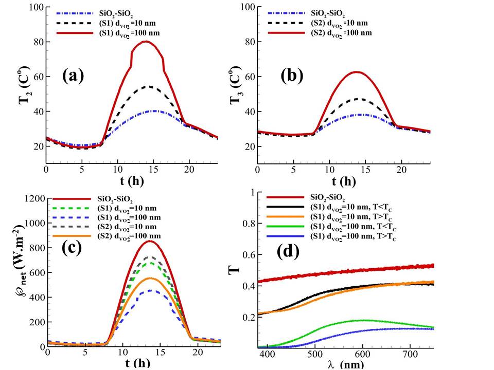
The net incoming heat flux , with respect to time, plotted in Fig. 4(c) is drastically reduced in comparison with a traditional window (double glazing SiO2-SiO2). This reduction is approximately at the midday when the VO2 film nm is deposited on the inner side of the external pane ( configuration in Fig. 1), a value representing of the solar irradiation at lattitude and about of the incoming flux through a traditional window. Such isolating behavior exceeds by far the performances of all previous smart windows rewiew_Feng ; rewiew_Cui . On the other hand, when the MIT layer is on the opposite pane ( configuration) the incoming net flux becomes, in comparison, more important, the temperature of this pane being increased by the greenhouse effect. For nm thick VO2 the thermal insulation is reduced by a third.
Beside the thermal characteristics of the window we show in Fig. 4(d) the transmittance
| (11) |
of the smart window in the visible range for both phases of thermochromic material. Here (resp. ) denotes the directionnal spectral transmission of the window under an incident angle (with respect to the normal, see Fig. 1) in (resp. ) polarization. Notice that this transmittance depends weakly, in the visible, on the crystallographic state of VO2 film, the main changes taking place mainly in the infrared. Although relatively small, this transmittance ( for nm thick VO2) over of spectrum is comparable with that of usual double glazing SiO2-SiO2. This transmittance falls down to with nm thick VO2, making the window partially opaque. Nevertheless, this value could be significantly improved using a nanostructured MIT layer without significantly affecting its properties in the infrared, as discussed in Ref. rewiew_Feng ; rewiew_Cui ; Taylor ; Liu . However, this could also significantly increase the overall fabrication cost. This problem as well as the optimization of the window will be addressed in a specific study.
In conclusion we have introduced a smart window based on a double glazing made with a SiO2-VO2 bilayer which is autonomously thermally and optically regulated by greenhouse effect. This system overcomes the primary weaknesses of thermochromic and electrochromic smart windows. Beyond its application in the developpemnt of smart windows for more sustainable buidlings, the passive insulation mechanism introduced in the present work could find broader applications in the development of self-regulated insulating materials for complex systems.
Acknowledgments
This research was supported by the French Agence Nationale de la Recherche (ANR), under grant ANR-19-CE08-0034 (PassiveHEAT). P. B.-A. acknowledges discussions with E. Blandre and A. Losquin.
Data availability
The data that support the findings of this study are available from the corresponding authors upon reasonable request.
References
- (1) T. Ramesh, R. Prakash, K. K. Shukla, Energy Build. 42, 1592 (2010).
- (2) H. Kim, Y. Kim, K. S. Kim et al., ACS Nano 7, 5769 (2013).
- (3) J. Zheng, S.Bao, and P. Jin, Nano Energy 11, 136 (2015).
- (4) T. Chang, X. Caoa, L. R. Dedon et al., Nano Energy 44, 256 (2018).
- (5) P. Ben-Abdallah and S. A. Biehs, Appl. Phys. Lett., 103, 191907 (2013).
- (6) P. Ben-Abdallah, H. Benisty and M. Besbes, J. Appl. Phys. 116, 034306 (2014).
- (7) P. Ben-Abdallah and S.-A. Biehs, Phys. Rev. Lett. 112, 044301 (2014).
- (8) A. Fiorino, D. Thompson, L. Zhu et al., ACS Nano 12, 5774 (2018).
- (9) D. G. Baranov, Y. Xiao, I. A. Nechepurenko et al., Nature Materials 18, 920 (2019).
- (10) V. Kubytskyi, S.-A. Biehs and P. Ben-Abdallah, Phys. Rev. Lett. 113, 074301 (2014).
- (11) P. Ben-Abdallah and S.-A. Biehs, Phys. Rev. B 94, 241401(R) (2016).
- (12) A. Cannavale, U. Ayr, F. Fiorito et al., Energies, 13, 1449 (2020).
- (13) S. Chen, Z. Wang, H. Ren et al., Sci. Adv. 5, eaav6815 (2019).
- (14) M. M. Qazilbash, M. Brehm, B. G. Chae et al., Science 318, 5857, 1750 (2007).
- (15) A. S. Barker, H. W. Verleur, H. J. Guggenheim, Phys. Rev. Lett. 17, 1286 (1966).
- (16) H. W. Verleur, A. S. Barker, C. N. Berglund, Phys. Rev. 172, 788 (1968).
- (17) Handbook of Optical Constants of Solids, edited by E. Palik (Academic Press, New York, 1998).
- (18) H. B. Awbi, Energy and Buildings 28, 219-227 (1998).
- (19) W. H. McAdams. Heat Transmission, McGraw-Hill Book Company, (New York, 3rd edition, 1954).
- (20) S.-A. Biehs, R. Messina, P.S. Venkataram et al., Rev. Mod. Phys., 93, 025009 (2021).
- (21) I. Latella, P. Ben-Abdallah, S.-A. Biehs et al., Phys. Rev. B 95, 205404 (2017).
- (22) S.M. Rytov, Y. A. Kravtsov and V. I. Tatarskii, Principles of Statistical Radiophysics, Vol. 3, (Academy of Sciences of USSR, Moscow, 1953).
- (23) NREL (2004), Reference Solar Spectral Irradiance: Air Mass 1.5 (rredc.nrel.gov/solar/spectra/am1.5).
- (24) M. Feng, X. Bu, J. Yang et al., J. Mater. Sci. 55, 8444 (2020).
- (25) Y. Cui, Y. Ke, C. Liu et al., Joule 2, 1707 (2018).
- (26) A. Taylor, I. Parkin, N. Noor et al., Opt. Exp. 21, A750 (2013).
- (27) S. Liu, C. Y. Tso, H. H. Lee et al., Sci. Rep. 10, 11376 (2020).