Safety-Aware Physical Human-Robot Collaborative Transportation and Manipulation with Multiple Aerial Robots
Abstract
Human-robot interaction will play an essential role in various industries and daily tasks, enabling robots to effectively collaborate with humans and reduce their physical workload. Most of the existing approaches for physical human-robot interaction focus on collaboration between a human and a single ground robot. In recent years, very little progress has been made in this research area when considering aerial robots, which offer increased versatility and mobility compared to their grounded counterparts. This paper proposes a novel approach for safe human-robot collaborative transportation and manipulation of a cable-suspended payload with multiple aerial robots. We leverage the proposed method to enable smooth and intuitive interaction between the transported objects and a human worker while considering safety constraints during operations by exploiting the redundancy of the internal transportation system. The key elements of our system are (a) a distributed payload external wrench estimator that does not rely on any force sensor; (b) a 6D admittance controller for human-aerial-robot collaborative transportation and manipulation; (c) a safety-aware controller that exploits the internal system redundancy to guarantee the execution of additional tasks devoted to preserving the human or robot safety without affecting the payload trajectory tracking or quality of interaction. We validate the approach through extensive simulation and real-world experiments. These include as well the robot team assisting the human in transporting and manipulating a load or the human helping the robot team navigate the environment. To the best of our knowledge, this work is the first to create an interactive and safety-aware approach for quadrotor teams that physically collaborate with a human operator during transportation and manipulation tasks.
Index Terms:
Aerial Robotics, Physical Human-Robot InteractionSupplementary material
Video: https://youtu.be/c1mj3be02cI
I Introduction
As envisioned in the Industry 4.0 revolution, human-robot interaction will play a more important role in future industries and daily life [1]. Most research on human-robot interaction focuses on collaboration between humans and ground robots. Only a few approaches exist for aerial robots, mostly limited to teleoperation. Compared to ground robots, collaborative Micro Aerial Vehicles (MAVs) show additional flexibility and maneuverability brought by their 3D mobility and small size. Moreover, a team of collaborative MAVs can provide increased adaptivity, resilience, and robustness during a task or multiple simultaneous tasks compared to a single aerial robot. For example, teams of MAVs can assist humans in completing some complex or dangerous tasks. These include, but are not limited to inspection [2, 3], mapping [4, 5], environment interaction [6, 7], surveillance [8], and autonomous transportation and manipulation [9, 10]. Specifically, in autonomous aerial transportation and manipulation, there are many possible usage scenarios. For instance, in a post-disaster response task, a team of aerial robots can cooperatively deliver emergency supplies to designated rescue locations based on the first respondent’s guidance. Alternatively, on a construction site, an aerial robot team can cooperatively manipulate over-sized construction materials with human workers to speed up the installation process and reduce their physical workload.
This paper proposes a novel approach that enables a team of aerial robots to transport and manipulate a cable-suspended payload in safe physical collaboration with a human operator, as depicted in Fig. LABEL:fig:Intro. As discussed in [11], the choice of cable mechanisms stands out compared to other existing solutions, such as simple spherical joints, robot arms [12], because of their lighter weight, lower costs, simpler design requirements, and zero-actuation-energy consumption. Therefore, they are particularly suited for Size, Weight, and Power (SWaP) aerial platforms. Cables also present a good balance among maneuverability, manipulability, and safety for physical human-aerial-robots collaboration compared to other solutions. For instance, several solutions attach the robots directly to the payloads via passive mechanisms like spherical joints [13], magnets [14] or active mechanisms like gripper [15]. However, these mechanisms present lower maneuverability and manipulability during a manipulation or physical interaction task compared to cables. Conversely, other complex actuated solutions based on robot arms [16, 17, 18] can increase maneuverability and flexibility. However, this generally comes at the price of increasing the inertia and power of the system which may affect the operator’s safety requirements. Therefore, we believe that lightweight cable mechanisms can provide compared to other existing solutions a good trade-off in terms of maneuverability, manipulability, and safety while concurrently offering a good flexibility to execute multiple tasks.
We introduce a novel control, planning, and estimation framework that allows the human operator to physically collaborate with a quadrotor team to transport and manipulate a rigid body payload in all 6 Degrees of Freedom (DoF). Furthermore, the approach can exploit the system redundancy to enable the execution of secondary tasks such as obstacle avoidance or keeping a safe distance among the team agents and the human operator during collaboration, as shown in Fig. LABEL:fig:Intro (left).
Some existing approaches study the collaboration between humans and aerial robots but mostly with only one aerial robot [17, 19, 20]. When considering multiple aerial robots, a common solution is teleoperation [6, 21]. Few solutions exist for human physical interaction and collaboration with several MAVs [22, 23]. However, the human operator’s physical collaboration is limited to a 2D horizontal plane, and these approaches do not consider how to effectively exploit the additional DoF to increase both the operator’s and robots’ safety.
In summary, the contributions of this paper are the following
-
•
A safety-aware load position and orientation controller that can exploit the additional degrees of mobility of the system introduced by using multiple agents. Specifically, compared to existing solutions, our controller considers the full nonlinear dynamics of the quadrotor team carrying a tethered rigid-body payload while offering the ability to preserve human or robot safety.
-
•
A scalable and distributed cable-suspended payload external wrench estimator that does not depend on any external force sensors.
-
•
A 6D admittance controller for human-aerial-robot collaborative transportation and manipulation of a rigid-body payload.
-
•
A a set of extensive real-world experiments to validate the proposed solution.
To the authors’ best knowledge, this work is the first one proposing a safety-aware and interactive approach for quadrotor teams that allow seamless physical collaboration with human operators for collaborative transportation and manipulation of rigid-body payloads.
The paper is organized as follows. In Section II, we review the literature that is related to cooperative aerial manipulation and physical human-robot interaction. In Section III, we review the nonlinear system dynamics, considering the external wrench from a human operator. In Section IV, we discuss the proposed control framework that considers the nonlinear system dynamics and the safety of humans and robots. Section V presents the state estimation strategy and admittance control framework for intended human-aerial-robot collaborative manipulation. Section VI presents real-world experiments results on validating the proposed framework. Section VIII concludes the work and proposes multiple future research directions.
II Related Works
Cooperative Aerial Manipulation. In the subsequent discussion, we primarily concentrate on the control, planning, and estimation techniques specifically associated with aerial transportation and manipulation using suspended cables. This emphasis is due to the multiple aforementioned benefits that the cable mechanism offers compared to other mechanisms.
Past literature includes several control and estimation methods [11, 24, 21, 25] for autonomous aerial transportation and manipulation using multiple aerial robots equipped with cables. For example, several works [24, 25, 26, 27, 28] propose formation controllers for a team of MAVs to fly in a desired formation when carrying the suspended-payload. The carried payload is not modeled as an integrated part of the system but as an external disturbance that each MAV controller tries to compensate for. Therefore, it is expected that these solutions can struggle to transport the payload to a given position. In [29], by assuming the payload is a point-mass, the authors analyze the full nonlinear dynamics of the system. Based on the dynamic model, the authors design a geometric controller to transport the payload to the desired position moving the quadrotor team to accommodate the desired load motions. Moreover, the previously mentioned methods [29, 25, 26, 27], treat the payload as a point-mass, hence restricting the manipulation capabilities to payload’s positional movements only, with no control over its orientation.
Other approaches for autonomous aerial transportation and manipulation rely on a leader-follower paradigm [13, 30, 31, 32]. The leader robot follows the desired trajectory, whereas the followers maintain either a constant distance from the leader [31], or adapt to forces exerted on them when tracking their trajectory [33, 13]. However, these methods are subject to error compounding failure since they rely on the leader as a fundamental control unit for navigation. Furthermore, they cannot accurately guarantee the payload’s transportation to the desired location or manipulate its orientation.
Several works analyze the system’s complex nonlinear dynamics and mechanics and propose corresponding controllers to control the payload’s pose in 6 DoF [34, 35, 36, 37]. For example, in [36, 37], the authors assume the system is in a quasi-static state and analyze the corresponding static system mechanics. A payload pose controller assigns the quadrotors’ desired position to manipulate the payload to the desired pose. In [35, 34], the complex nonlinear dynamics in the system are thoroughly analyzed using Lagrangian mechanics. Leveraging this model, nonlinear geometric controllers enable the payload to follow the desired pose trajectory. More recently, several solutions propose optimal control strategies [38, 39]. Although all these works consider the payload a rigid body, the redundant control DoF available in the system [40] are not exploited to accommodate additional tasks like obstacle avoidance or to ensure safety distance among agents.
Some recent literature starts to investigate this aspect [21, 41, 7]. However, they are specifically designed for a team of three or four quadrotors. In [42], the authors attempt to leverage system redundancy for a team with an arbitrary number of aerial robots, implementing an optimization formulation for the parallel robot that exclusively optimizes the tension magnitude in the cables, without considering cable directions.
However, the methodology presented in [42] does not provide clear instructions for determining cable direction. Consequently, its applicability for secondary tasks such as obstacle avoidance or spatial separation from the human operator remains ambiguous. In this work, we formulate a general safety-aware controller for any quadrotors that exploit the additional system redundancy at the control level, allowing the system to achieve some secondary tasks, such as avoiding obstacles or keeping a safe distance among robots and human operators.
However, since the above methods are designed to control the payload’s pose explicitly, it is essential to have a reasonable estimation of the payload’s states (i.e., pose and twists) to be fed back into the controller to have a good tracking performance of the payload’s pose. Some estimation approaches can recover the payload pose in [21, 43], but they rely on GPS and, therefore, cannot be employed in indoor environments or areas where the GPS signal is shadowed. Conversely, in our previous work [11], we tackle the payload pose inference problem using onboard vision sensors and IMU to obtain closed-loop control of the payload pose.
However, the proposed vision-based estimation method might be subject to onboard visual-inertial odometry drift, leading to some constant offset errors. Although such errors will not affect the stability of the system, they will influence the task performance. For instance, consider a scenario where the system is required to transport a payload to a specific location, but due to state estimation drift, there is a 1-meter offset from the desired destination. In such cases, as shown in this paper, our proposed method enables a local human operator to guide the system and correct the payload to the desired pose, ensuring that the payload is transported to the correct final destination.
Physical Human-Robot Interaction. Physical Human-Robot Interaction (pHRI) is a rapidly growing field in robotics, facilitating the collaboration between humans and robots in various scenarios such as manufacturing, healthcare, and service industry. Most of the research in this field focuses on the collaboration between a single robot and a human. For instance, this includes cooperative manipulation with a robot arm attached to a ground wheeled base [44, 45], a fixed-base robot arm [46], a humanoid robot [47], or an aerial robot with a manipulator [17, 19]. Past Researchers’ works also present approaches like admittance control [48, 19], compliance control, impedance control for single-human-single-robot physical collaboration.
To increase payload capacity, the common strategies are either deploying a more powerful robot or utilizing a team of robots. The latter approach not only increases redundancy and provides the potential for fault tolerance, but also brings in specialized capabilities that enhance the team’s resilience and performance compared to a single robot. However, employing a team of robots demands effective coordination and collaboration across estimation, planning, and control levels.
While multiple robot-human interactions with teleoperation via haptic devices [49] or mixed reality glasses [50, 51] is a widely explored research topic, physical human-multi-robot cooperative manipulation with pHRI remains mostly underexplored [52]. Recently, a handful of works start to research on direct physical interaction between a human and multiple ground robots to cooperatively manipulate or transport an object [52, 53, 54]. In [54], the authors demonstrate that omnidirectional ground robots with robot arms can physically collaborate with a human using their proposed force-mediated controller but only simulation results were presented. In [52], the authors design an omni-robot system that can lift payloads. Then the multiple proposed omni-robots can collaborate with humans to manipulate objects toward desired locations. In [53], the authors use two robot arms with omnidirectional wheeled base to physically collaborate with a human to manipulate over-size objects. They introduce an admittance control module on both ground robots to adapt the human motion as the human leads the manipulation. However, since the system dynamics for aerial robots are inherently different from ground robots, the established dynamics models and corresponding control methods for ground robots cannot be directly translated to aerial robots.
In [22], the authors propose a framework for physical human-robot collaborative transportation of cable-suspended payload with a team of quadrotors. The proposed approach models the payload as a point mass and assumes external forces applied on the payload to be constrained in 2D. Leveraging their previous work [31], the designed controller assigns three quadrotors as leaders and the remaining robots as followers in the team. When an external force is applied to the payload, a fixed step is given to the leaders’ positions along the estimated force direction. In [23], five quadrotors collaborate with a human operator to transport a point mass payload. The force applied by a human on the payload is estimated by summing the cable tension forces and subtracting the gravity. The human-applied force is fed into an admittance controller, which updates the desired quadrotor position and velocity in the formation. However, compared to our work, the cable tension magnitude is measured by a custom tension measurement module, and its direction by a motion capture system. Moreover, the aforementioned works present substantial limitations as they presume the payload to be a point-mass and constrain the human operator to manipulate the payload in only 2D. On the contrary, in our proposed work, we widen the scope of physical interactions between the human operator and the payload to all DoF. This enhancement is achieved by modeling the payload as a rigid body with DoF and developing an estimator to estimate the full DoF wrench acting on the payload. Furthermore, our system removes the use of any force-measuring devices on the robots or payload (except to obtain the ground truth during testing for validating our estimation approach). These are unique characteristics that increase the flexibility and applicability of our solution compared to existing ones.
III System Dynamics
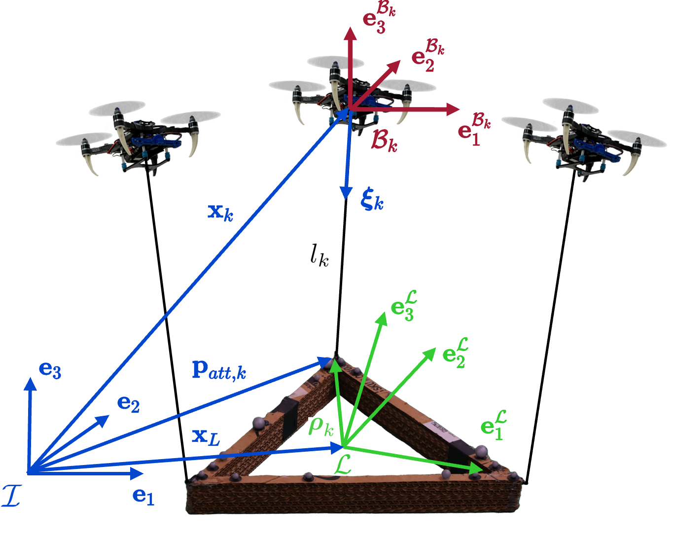
In this section, we introduce the overall system dynamics modeling. We consider a team of MAVs cooperatively transporting a rigid body payload. Each MAV has one massless cable attached from it to the payload, as depicted in Fig. 1. Without loss of generality, the system’s world frame fixes at a location on the ground. The payload frame, , is located at the center of mass of the payload and initially coincides with . The relevant variables in our problem are stated in Table I. For any 3 dimensional vector in this paper, we use subscripts represents the 3 elements in the vector correspondingly.
The system dynamics models are developed based on the following assumptions
-
1.
Aerodynamic interactions with the ground and other effects caused by high robot velocity are ignored due to its insignificant effect at a low moving speed that’s achieved by this system;
-
2.
Each cable is assumed to be attached at the center of mass of each robot, each robot’s center of gravity coincides with its geometrical center, and all cables are assumed to be massless with no dynamic effects on the system;
-
3.
Wind disturbances are ignored, the human operator would only interact with the payload, and all external forces on the payload and each robot are considered to be exerted by a human operator.
Assumption 1 is made based on the operational velocity, as well as based on the fact that, with our proposed framework, we can specify a spatial distance among agents to minimize these effects. This can also be enforced in our safe aware controller presented in Section IV-B. Assumption 2 is considered valid as a result of the symmetrical design of the MAV and the lightweight nature of all the cables used. Assumption 3 is based on the fact that in this work, we tackle indoor operating conditions.
| , , | world frame, payload frame, robot frame |
| mass of payload, robot | |
| position of payload, robot in | |
| linear velocity, acceleration of payload in | |
| linear velocity, acceleration of robot in | |
| orientation of payload with respect to | |
| orientation of robot with respect to | |
| yaw, pitch, row of robot with respect to | |
| , | payload’s angular velocity, acceleration in |
| , | robot’s angular velocity, acceleration in |
| moment of inertia of payload, robot | |
| unit vector from robot to attach point in | |
| , | angular velocity, length of cable |
| tension magnitude within the cable | |
| external human force, net force on payload in | |
| external human moment on payload in | |
| net moment on payload in | |
| total thrust of quadrotor | |
| control force on robot in | |
| control moment on robot in | |
| attach point position in | |
| human position, attach point position in |
III-A Payload Dynamics
As shown in Fig. 1, we consider the payload suspended by MAVs. The net force in and moment in on the payload is determined by all the cable tension forces , , gravitational pull , and external wrench applied by the human operator
| (1) |
where , , . In eq. (1), the matrix maps tension vectors of all MAVs in to the wrench on the payload with force in and moments in
| (2) |
where the hat map is defined such that . Through eq. (1), we can obtain the translational and rotational dynamics of the payload as
| (3) |
where is the payload mass, is the payload linear and angular acceleration respectively, is the payload angular velocity and is the payload’s inertia matrix.
III-B Quadrotor Dynamics
As shown in Fig. 1, the cable attached to the quadrotor is attached to the payload at point . The location of the attach point with respect to is represented by constant vector . Based on assumptions 2 and 3, we consider the translational and rotational dynamics of the quadrotor as follows
| (4) |
| (5) |
where and are the control force and moment on the quadrotor, is the tension force applied on the quadrotor.
IV Control
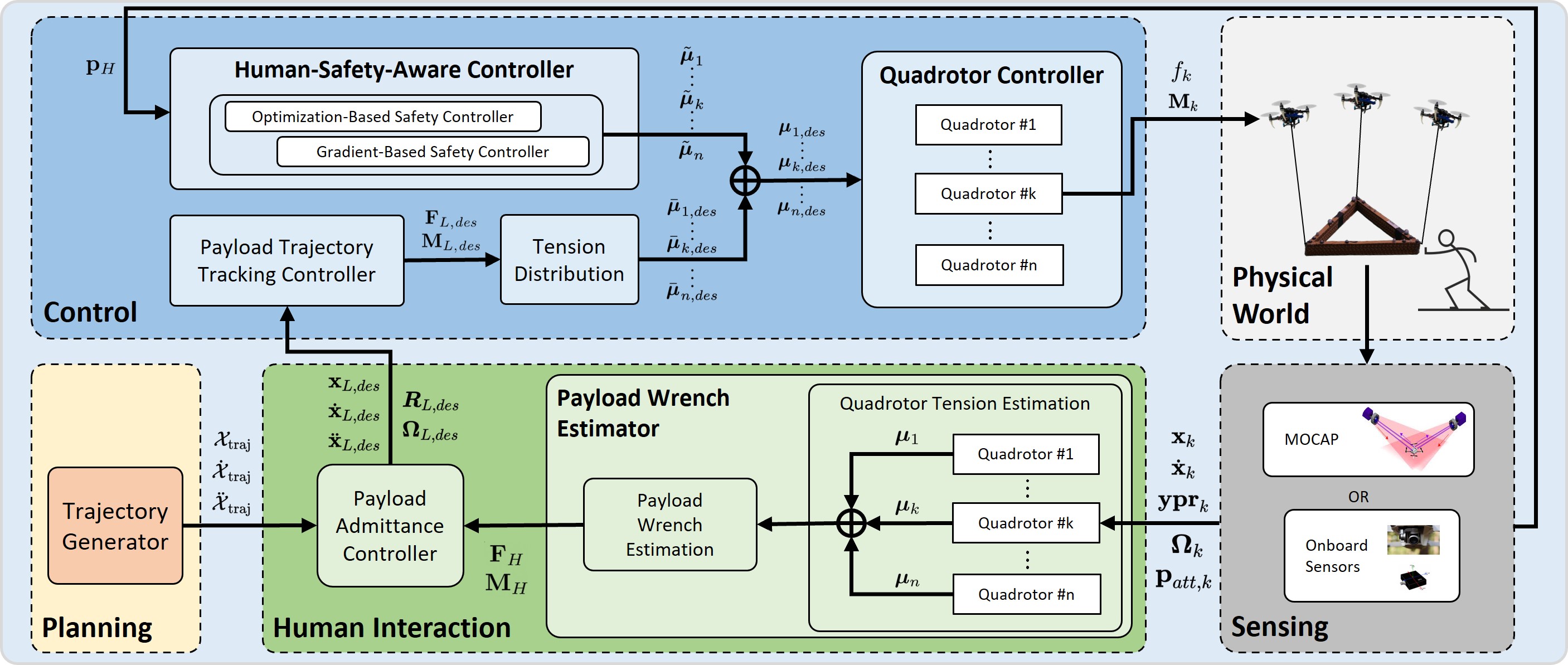
In this section, we present a hierarchical nonlinear controller that enables a team of quadrotors to manipulate a rigid-body load suspended by cables. The controller is formulated based on the system dynamics presented in Section III. As shown in Fig. 2, we employ a hierarchical formulation for the controller like our previous work [11], which is based on the theoretical results shown in [40].
The formulation starts from a payload controller described in Section IV-A that generates the desired wrenches to control the position and orientation of the payload. Then the desired wrench is distributed to obtain desired cable tension vectors for each robot.
As discussed in Section I, compared to existing control solutions, the proposed approach allows, for number of robots, to control the payload’s full pose explicitly while concurrently exploiting the system redundancy to execute the additional tasks. As we will present in Section IV-B, the key idea is to exploit the additional system redundancy to increase system safety by guaranteeing a spatial separation between the robots and some objects in the environments. To achieve this goal, we propose and discuss two different approaches. Overall, the system will distribute the wrench to the desired cable tension forces by considering two key goals
-
1.
Minimize the total cable tension forces to save the robot’s energy.
-
2.
Exploit the null space of the cable distribution matrix to achieve secondary tasks such as keeping safety distance between robots and possible human operators in the team.
Finally, the robot controller will input the desired tension vector to generate the corresponding thrust and moment as presented in Section IV-C.
IV-A Payload Controller
We present a payload controller that enables the load to follow the desired trajectory in a closed loop. The subscript denotes the desired value given by the trajectory planner. The desired forces and moments acting on the payload are designed as
| (6) |
| (7) |
where , are diagonal positive constant matrices, and
| (8) |
IV-B Safety-Aware Controller
Once the desired payload wrench , is obtained, these can be distributed to the desired tension force along each cable as
| (9) |
where is the Moore-Penrose inverse of for full-column-rank matrices. The above solution can be directly used as the desired cable tension vector for the robot, like in our previous works [9, 11]. However, the above solution does not exploit the possibility for the quadrotor team’s needs to accomplish secondary tasks, for example, avoiding obstacles or, as shown in this paper, increasing human operator safety during physical collaboration when transporting or manipulating a rigid-body payload.
In the following, we propose two methods that enable each of the MAVs to maintain a minimum safe distance from an object, which is a crucial metric for measuring the safety between robots and human collaborators [55], meanwhile still applying the original and from the Section IV-A, therefore not influencing the original load configuration. The proposed methods exploit the redundancy introduced by using more than three MAVs. Moreover, as the number of DoF of the payload is , and each cable provides control force on the payload in DoF, for any number of robots , , we can exploit the additional system redundancy in . Specifically, the null space of , , quantifies such redundancy.
Let us assume to find a tension modifier, , that modifies in eq. (9), and , then we have
| (10) |
and the updated robot’s desired cable tension force is
| (11) |
Intuitively, provides all the possible combinations of cable tension vectors that can generate internal motions of the structure (i.e., variations of the cables’ directions) that do not affect the load configuration controlled by the method presented in Section IV-A. This is confirmed by eq. (1) and eq. (11), as would create a nonzero net wrench on the payload while creates zero net wrench. Moreover, can be related to the position of each robot
| (12) |
where is the cable length when the cable is taut, and
| (13) |
The advantage is that we can exploit to enforce the robot to maintain a safe distance between the other agents in the system and other objects in the environments, like a potential human operator. Therefore, the safety controller needs to find the aforementioned tension modifier, , and use eq. (11) to move MAVs based on eq. (12) without affecting payload. We propose the following two approaches for finding
-
1.
Gradient-Based Safety Controller: Find a such that each MAV maximizes the distance between itself and the object using a gradient ascent method.
-
2.
Optimization-Based Safety Controller: Find a such that each MAV guarantees a predetermined minimal safe distance between all its neighboring drones and the object by using nonlinear optimization.
In the following, we can describe the obstacle or human operator as a particular object of interest in the environment. The corresponding point position with respect to is denoted as in the following controller formulation.
Gradient-Based Safety Controller: Inspired by strategies used for redundant rigid link robot arm in [56], we introduce a gradient-based method to compute . Specifically, a pseudo-tension-modifier, , is found by maximizing the distance between objects in the environment and each drone. is then projected into to become the tension modifier . To update the pseudo-tension-modifier, we propose
| (14) |
where is a diagonal positive-definite matrix with variable and tunable coefficients on its diagonal. And is the cost function and is defined as the squared distance between each drone and the object from which the system is required to keep a safe distance
| (15) |
where . Note that points from the attach point to the robot. Computing the partial derivative of the cost function for the robot using eq. (15), we have
| (16) |
For each control step, we update based on eq. (14), performing gradient ascent to maximize the distance between each robot and the objects in the environment. To regulate the effect of gradient on each robot when the object is far away, we propose each element of as a function of the robot-to-object distance of exponential decay type
| (17) |
where, are tunable coefficients. With this varying coefficient, distance limit is achieved to ensure the effect of gradient is particularly significant when robot is close to the object, from eq. (14) is not yet in . We consider the following optimization problem
| (18) | ||||
| s.t. |
The closed-form solution [57] for this quadratic programming problem is
| (19) |
where is the pseudoinverse as in eq. (9). will be full-column-rank if we have redundancy (i.e., ). is a particular null space projector that projects any orthogonally into the null space of . We project into with eq. (19), ensuring zero additional wrenches being applied on the payload when each robot is maximizing distance from the object. Finally, we update the desired tension vector as
| (20) |
Optimization-Based Safety Controller: In this section, we directly formulate an optimization problem to solve for a tension vector in that guarantees safety distance among the objects and the robots. The nonlinear optimization problem is to minimize the total square norm of the resulting cable tension vector. Furthermore, we formulate predetermined robot-to-object distance constraints. Additionally, another constraint is added between each pair of robots to prevent robot collision. Consider the following nonlinear optimization problem
| (21) | ||||||
| s.t. | ||||||
where spans and is the vector to be optimized. and are two scalar values denoting the predetermined safe minimum distance allowed between robots and between the object and each robot, respectively. The robot’s position is expressed in terms of and
| (22) |
where represents the three rows of the null space basis matrix for the MAV. Since eq. (21) is a nonlinear optimization problem with quadratic cost function and quadratic constraints, we use sequential quadratic programming solver for nonlinearly constrained gradient-based optimization [58] in NLOPT [59] to solve eq. (21) and obtain . After obtaining , the desired cable tension forces can be obtained as follows
| (23) |
Discussion: The proposed methods are both effective for the quadrotor team to keep a safe distance away from a given object, as we also experimentally verify in Section VI. However, considering computational aspects, the gradient-based method requires fewer resources compared to the optimization-based method. This is primarily due to the closed-form solution offered by the gradient-based approach, as demonstrated by eq. (16). On the other hand, the optimization-based method needs to solve a nonlinear optimization problem. In Section VII, we provide a quantitative analysis of the computational complexity and resource usage for both methods based on our implementation.
IV-C Robot Controller
In this section, we present the controller on each robot that enables the quadrotor to execute the desired cable tension force. The same robot controller has been used in our previous works [11, 9].
Once we obtain the desired tension forces from eq. (20) or eq. (23), we can obtain the desired direction and the desired angular velocity of the cable link as
where is the derivative of the desired cable direction . After we obtain the desired cable direction and cable angular velocity , we can determine the desired force vector for the robot as
| (24) |
where and are diagonal positive constant matrices, and are the cable direction and cable angular velocity errors respectively
As we obtain the desired force vector of the quadrotor, we can follow the attitude control of quadrotor [60] to derive the desired rotation and angular velocity with desired yaw angle and desired yaw angular velocity from the robot’s own planner. The thrust command and moment command to the quadrotor are therefore selected as
| (25) | ||||
| (26) | ||||
where , are diagonal positive constant matrices, and are the orientation and angular velocity errors similarly defined using eq. (8). The readers can refer to [40] for stability analysis of the controller. The aforementioned derivation addresses the challenges related to transitioning the nonlinear geometric controllers from theory to practice by showing a clear hierarchical formulation that can run on real robots.
V Physical Human-Robot Interaction
This section introduces the physical human-robot interaction module that enables a human operator to physically cooperate with a team of quadrotors in manipulating a suspended rigid-body payload. The module comprises two primary subsections: the estimation module and the admittance controller that we present in the following.
The estimation module is designed to facilitate the quadrotor team in estimating the human operator’s input wrench exerted on the payload. The admittance controller takes the estimated human wrench and the desired payload state as input and generates a desired payload state to adapt the human’s action.
V-A State Estimation
We present the estimator design that allows the quadrotor team to estimate the external wrench applied to the payload by the human operator. First, in Section V-A1, we introduce a quadrotor state estimator based on Unscented Kalman Filter (UKF) that runs onboard each quadrotor in a distributed fashion. Each quadrotor can leverage the estimator to estimate the cable force applied to it, without the need for a force sensor. Subsequently, in Section V-A2, we show how we can estimate the external wrench applied on the payload by the human operator via sharing the cable force on each quadrotor among the team.
V-A1 Robot State Estimator
We consider the MAV to have the following state
| (27) |
where are the robot orientation Euler angles expressed according to the ZYX convention and the input are defined as
| (28) |
where is defined in the dynamic model and the attach point and is obtained based on motor speed values from the electronic speed controllers as
| (29) |
where is the known motor constant, is the motor speed of the motor. Denote the current time step as and the previous time step as . Now we will present the nonlinear process model and the linear measurement model of the UKF.
Process Model
Based on MAV equations of motion presented in eq. (5), discretizations of quadrotor states are performed by assuming each control step moves forward in time by . The discrete-time nonlinear process model is
| (30) |
with
| (31) |
For updating the Euler angle, a few nonlinear mappings are used as in [61]
-
1.
that maps to .
-
2.
that maps to ; or maps axis-angle , to rotation matrix .
In eq. (31), is rotated into . After stepping , the new robot angular position in represented in is mapped into . This new angular position in is then added to the previous orientation. The resultant orientation is mapped to the Euler angle with . The equations of motion for unit cable direction are presented in [11]. Here, we provide the result
| (32) |
We consider a the time invariant process noise diagonal covariance matrix, under the assumption that our system is subject to zero mean, additive Gaussian process noise. To predict with the process model, the UKF algorithm calls eq. (31). Since measurement does not necessarily arrive at every control time step, nonlinear prediction with zero process noise is used.
Measurement Model
Using an indoor MOCAP system, we can measure everything in the state except tension magnitude. The measured states for robot therefore are
| (33) |
We also want to note that using onboard Visual Inertial Odometry and vision-based methods from our previous work [11] can provide the same measurements as the motion capture does and can potentially make the entire measurement update process run fully onboard.
Denoting the time step when UKF measurement update is triggered as , the UKF finds the state prior to , . A nonlinear propagation through eq. (31) is performed by propagating sigma points around through the system model in eq. (31) as shown in [62].
The linear measurement model is
The system state prediction is compared to the actual measurement using the above model
| (34) |
where is the averaged state after sigma point propagation and is the Kalman gain. Kalman gain is computed based on the standard UKF update step as in [62].
V-A2 Payload Wrench Estimator
Rearranging eq. (1), we obtain
| (35) |
Considering quasi-static operating conditions, we can assume the payload linear and angular accelerations terms can be neglected. Therefore, leveraging this assumption and rearranging based on eq. (35) we obtain
| (36) |
Extracting tension values from each robot’s state allows us to compute the external wrenches on the payload.
V-B Payload Admittance Controller
The admittance controller is a high-level controller that updates and in eq. (8) for the payload controller (Section IV-A) based on the external force applied on the payload. When interacting with the payload, it allows the human operator to experience a virtual mass-spring-damper system rather than the actual mass. By setting the admittance controller’s tunable parameters to the desired values, the payload can be either sensitive or insensitive to external forces regardless of the payload’s actual property.
The admittance controller treats the payload as a virtual mass-spring-damper system as the external force applied to the payload. The input is a payload external wrench, . The output includes payload twist, , and payload linear and angular position, , with angular position represented by Euler angle. The admittance controller also computes payload linear and angular acceleration, , but the lower level payload controller does not use this output. The controller assumes the following dynamics for the payload
| (37) |
where , , and are tunable diagonal positive semidefinite matrices denoting the desired mass, damping, and spring property of the payload, defined as follows:
| (38) |
where represents parameters corresponding to the axes of the translational motion, and denotes parameters associated with the roll, pitch, and yaw directions of the rotational motion, respectively. Based on the initial starting condition of the payload, , , and can be set accordingly. We choose to set them to be the planned trajectory. Closed-form solutions exist for eq. (37) with the assumption that the input wrench is a predetermined function (e.g., a linear function). However, such an assumption is not ideal for our use case. Therefore, we choose to solve , , with Runge-Kutta order approximation.
VI Experimental Results
The experiments are conducted in an indoor testbed with a flying space of of the ARPL lab at New York University. We use three quadrotors to carry a triangular payload via suspended cables. The quadrotor platform used in the experiments is equipped with a 801 board for on-board computing [63]. A laptop equipped with an Intel i9-9900K CPU obtains the Vicon 111www.vicon.com motion capture system data via ethernet cable and runs the optimization-based safety controller.
The framework has been developed in ROS222www.ros.org and the robots’ clocks are synchronized by Chrony333https://chrony.tuxfamily.org/. The mass of the payload is , which exceeds the payload capacity of every single vehicle. The odometry of the payload and quadrotors, the position and velocity of attachment points, and the human operator’s position are estimated using the Vicon data at a frequency of . The unit vector of each cable direction and the corresponding velocity are estimated by
| (39) |
where are position and velocity of the attach point in and are position and velocity of the robot in , all of which are estimated by the motion capture system.
VI-A Cable Force and External Wrench Estimation
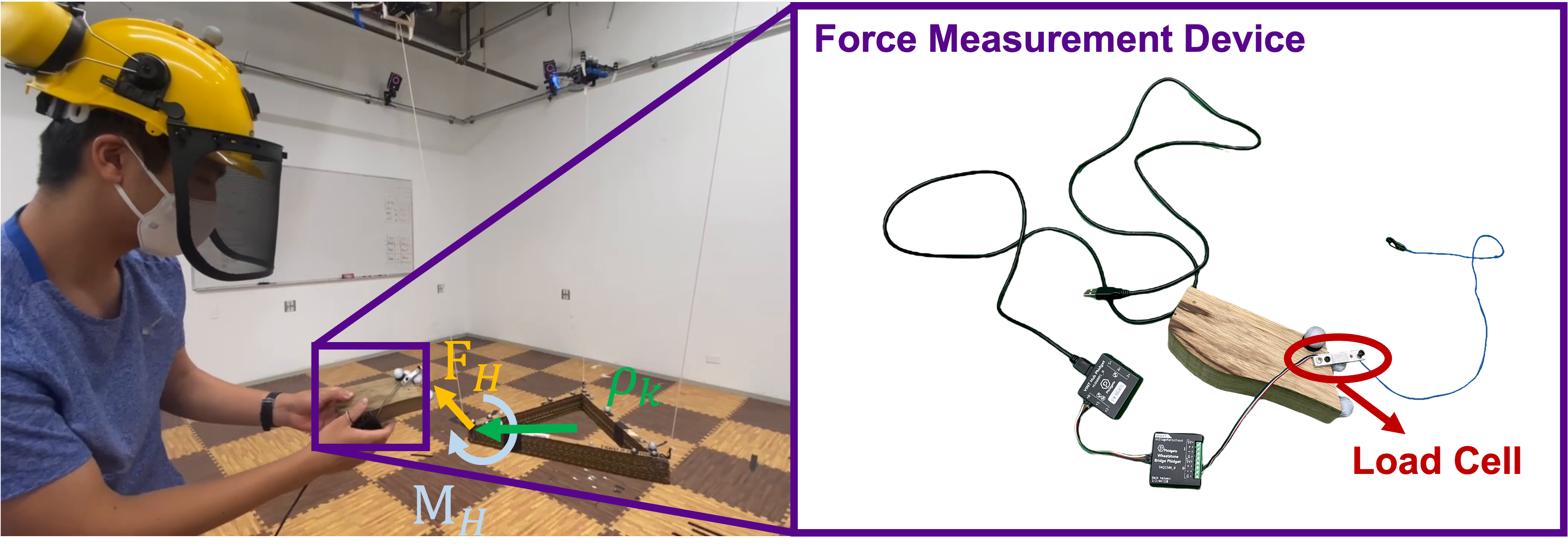
In this section, we validate our cable force and external wrench estimation algorithm by comparing the estimation results obtained using the approach presented in Section V-A2 with the ground truth from the wrench measurement device as shown in Fig. 3.
We can identify the ground truth force by measuring the force direction and force magnitude separately via the wrench measurement device. As the ground truth force direction is along the cable between the measurement device and the other end where the device is attached to the system, it is measured by computing the difference between the load cell’s position and the attach point position using the Vicon motion capture system. The ground truth force magnitude is measured via a Phidget micro load cell444www.phidgets.com as shown in Fig. 3. The measured cable direction and tension magnitude are post-processed to yield the ground truth force.
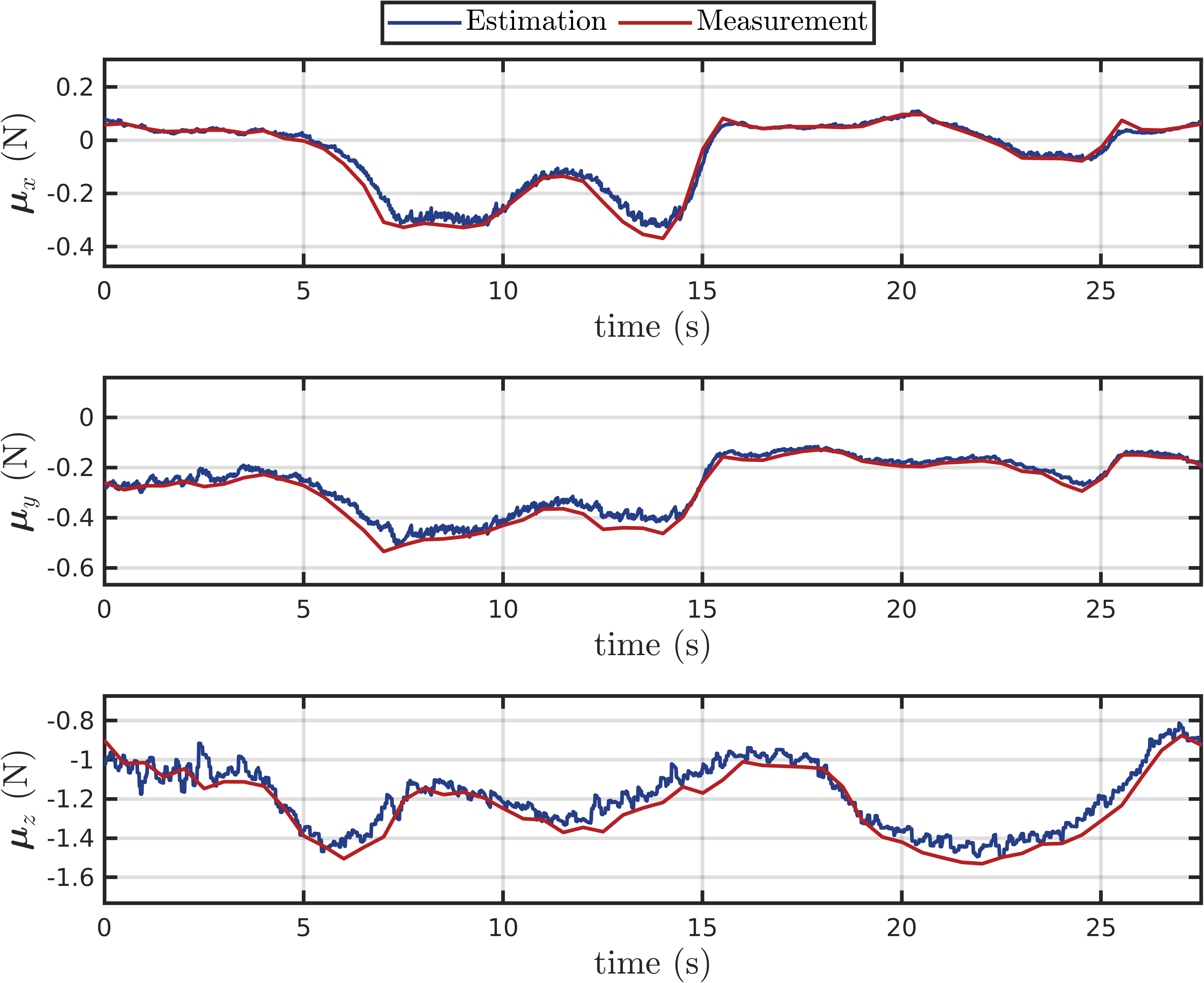
In the cable force estimation experiment, we hover a quadrotor in midair and run the proposed cable tension filter onboard. The measurement device is connected to the center of mass of the quadrotor and a human operator pulls the measurement device into various directions to evaluate the algorithms. The results are shown in Fig. 4. In the plots, we compare the measured forces to the estimated forces in all DoF and the estimated cable forces track measured ground truth accurately.
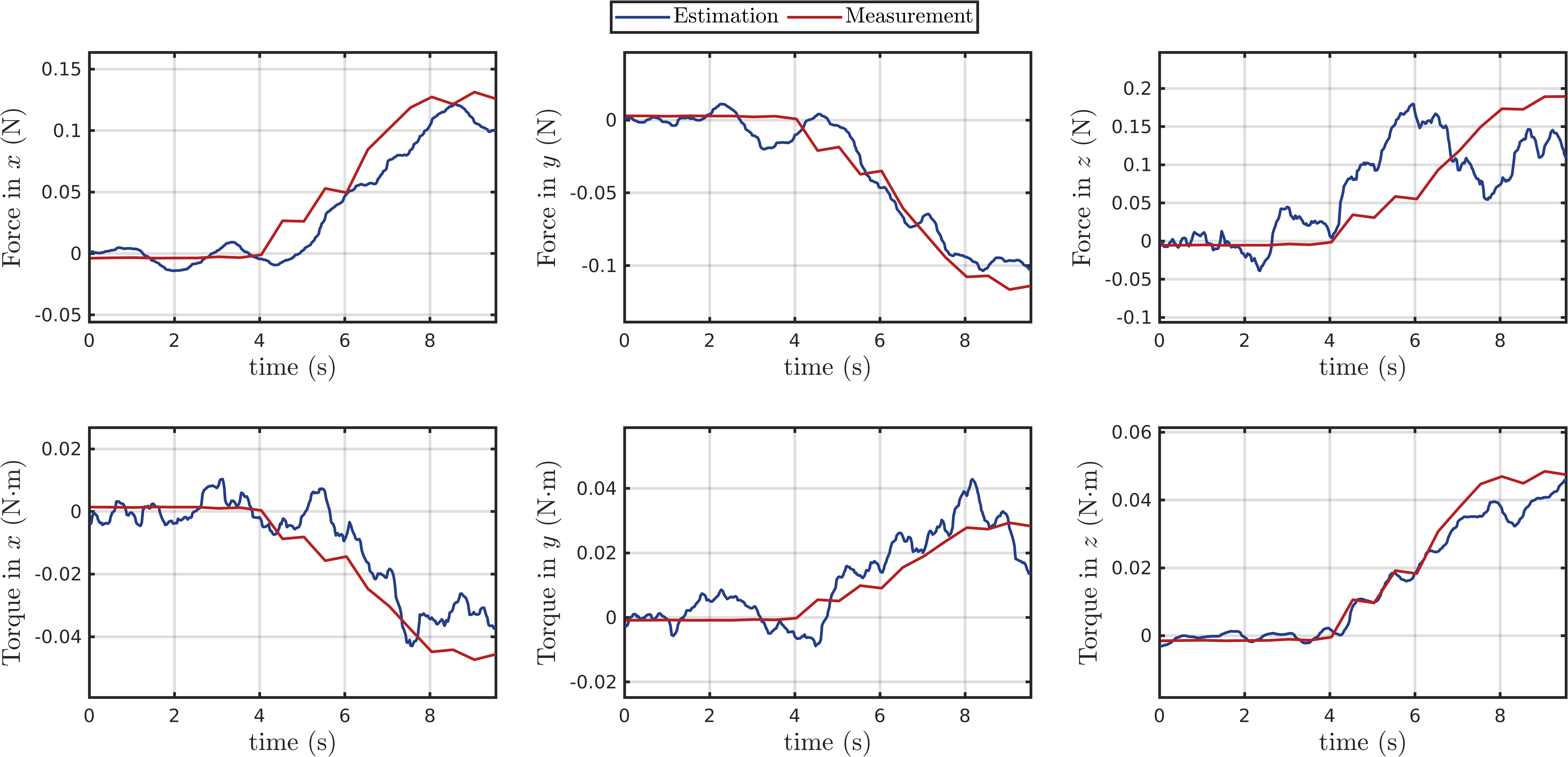
During the wrench estimation experiment, we hover the system with the regular payload controller without activating the admittance controller. Subsequently, the human operator pulls the payload with the force measurement device, and we record both the ground truth wrench and the estimation results. In addition to the ground truth force, the ground truth external torque is obtained by crossing the attached point position vector in and the measured ground truth force vector from the measurement device. The payload is pulled so that the external wrench is non-zero in all six DoF, as shown in Fig. 3.
The results are shown in Fig. 5. In the plots, we compare the measured wrenches to the estimated wrenches in all 6 DoF. The estimated wrenches track measured ground truth quite accurately. In the direction, however, the estimation deviates from measurement. We believe this is caused by the hybrid dynamics switching when the payload is pulled in the positive direction. The root mean squared errors in all six directions are also reported in Table II, confirming a good accuracy.
| Force () | Moment () | |||||
| roll | pitch | yaw | ||||
| 0.0185 | 0.0117 | 0.0564 | 0.0088 | 0.0066 | 0.0045 | |
VI-B Admittance Control with Wrench Estimation
After validating the wrench estimation, we jointly test it with the admittance controller.
VI-B1 Virtual Impedance Realization
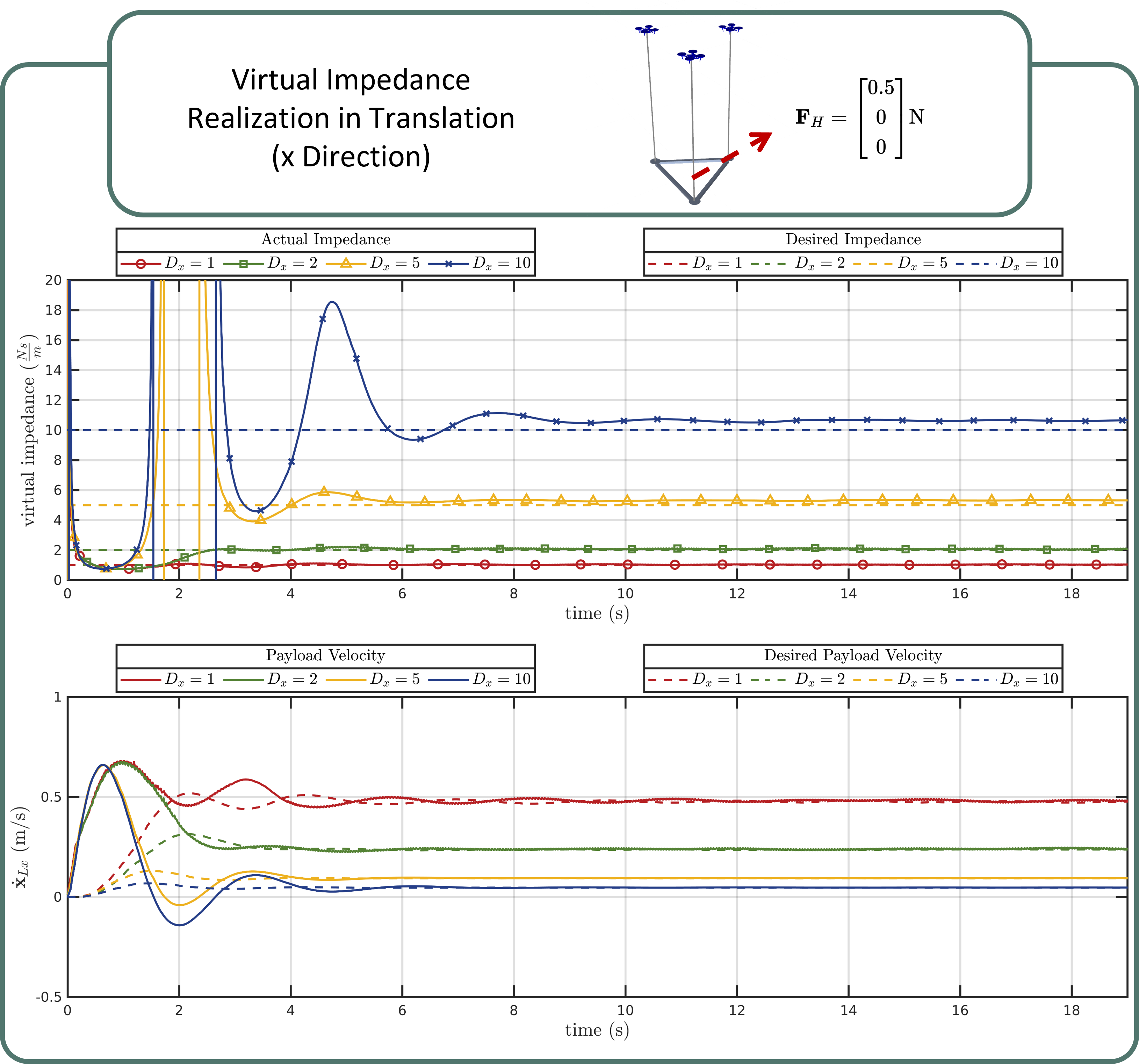
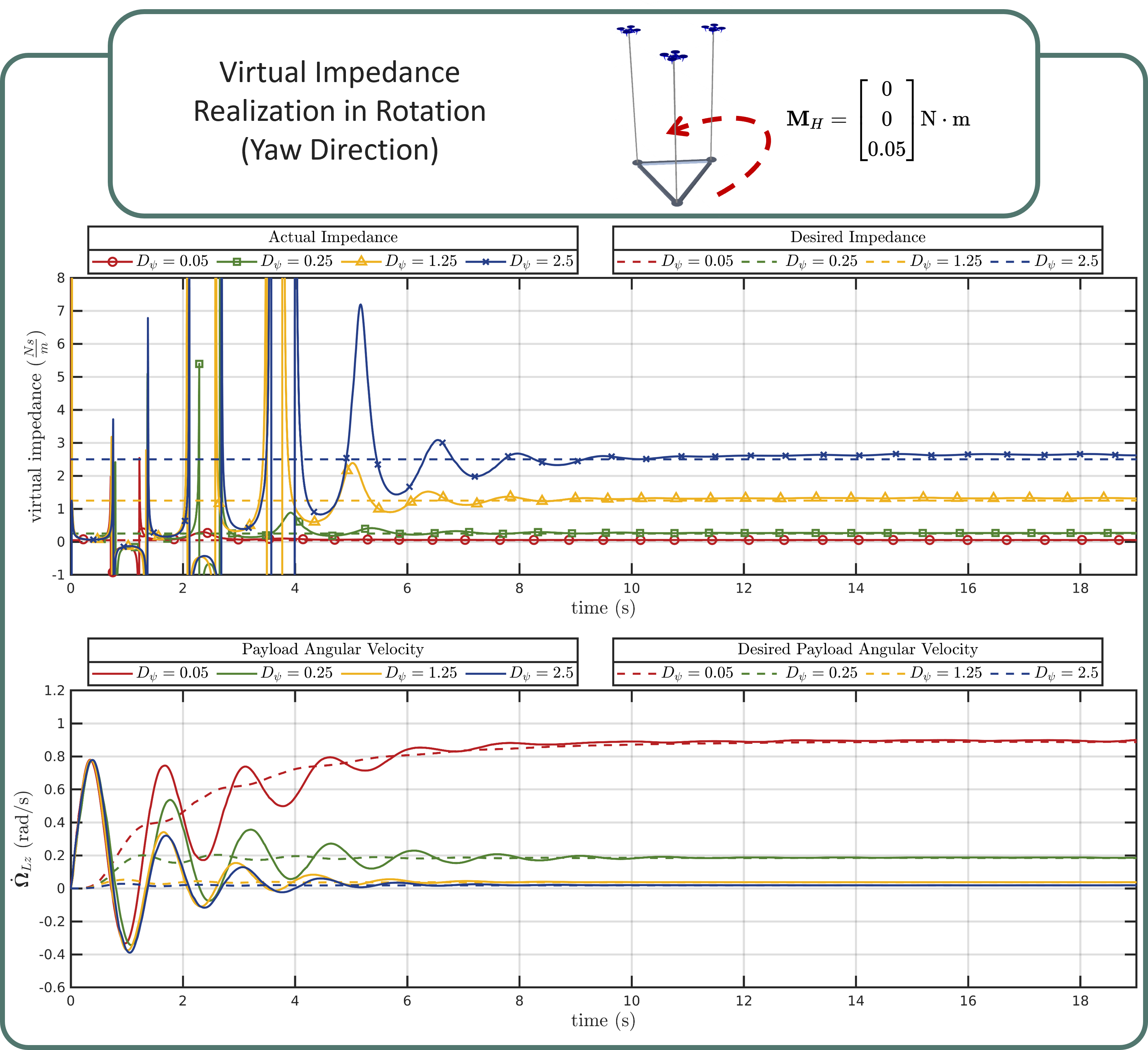
In this section, we present results in simulation to quantitatively analyze the performance of our system, particularly regarding the rendering of the desired virtual impedance of our proposed system. We deploy a robot team that consists of “Dragonfly” quadrotors with cable in our open-source simulator [64] to validate the realization of desired impedance values. In the experiments, we introduce a step wrench input and observe the system’s response.
In the first experiment, we apply a step force input of on the payload in the positive direction and set different impedance values (, , , ) in the admittance controller. The second experiment involves the application of a step moment input of on the payload in the positive yaw direction, with different impedance values (, , , ) set in the admittance controller. The results are shown in Figs. 6 and 7. We evaluate the actual impedance in the system using the ground truth force and moment, divided by the actual velocity of the payload along the corresponding direction. Hence the actual impedance we obtain in Fig. 6 and Fig. 7 are and , respectively. In the plots, we compare the actual impedance with the desired impedance set in the admittance controller.
As illustrated by the plots, upon application of step force and moment inputs to the system, the payload promptly accelerates in the and yaw directions, respectively. As the wrench estimation updates, the admittance controller starts to adjust the desired payload state to adapt the human input, shown by the dashed lines in the bottom plots in both Figs. 6 and 7. Through the comparison, we can see that with larger values of , the desired velocity derived from the admittance controller evolves slower and smaller in magnitude. As the experiment proceeds, the desired velocity ultimately converges to final values, respectively equivalent to and .
Moreover, a larger desired impedance value results in noticeable spikes in the actual impedance before the convergence. This can be attributed to the fact that a higher impedance value leads to a smaller corresponding desired velocity, which in turn causes larger velocity errors at the initial stage. This subsequently results in an overshooting response of the actual payload velocity, causing it to cross the zero line and trigger spikes in the actual impedance realization.
Lastly, as the experiments progress and the transient effects resulting from the step input reduce, the payload’s linear and angular velocities converge toward the desired payload velocity determined by the admittance controller. Consequently, the actual virtual impedance also aligns with the value set by the admittance controller. We observe similar results for the other Cartesian and angular axes that are not reported for simplicity.
VI-B2 Real-World Experiments
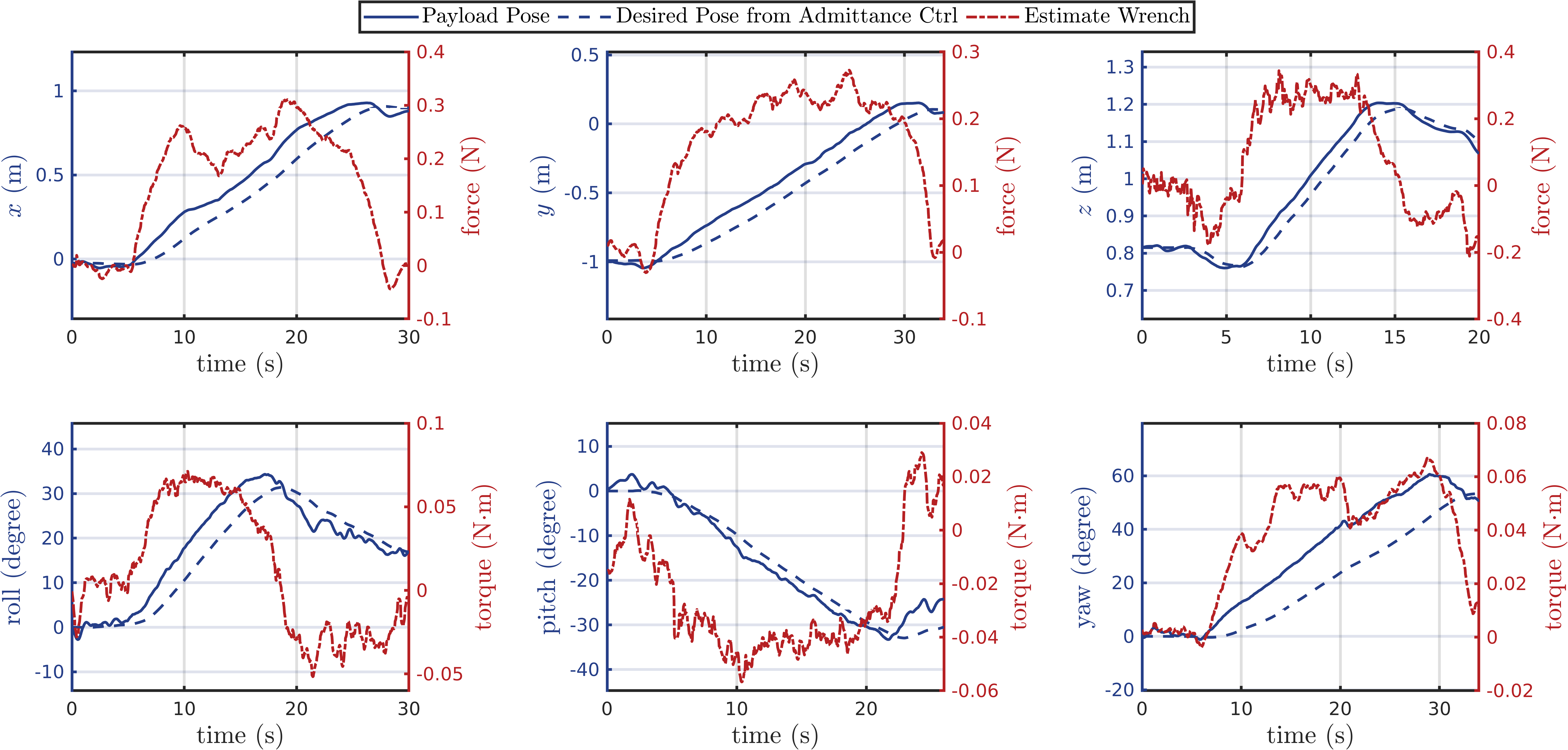
We conduct six tests involving all DoF of the admittance controller in real-world experiments. The human operator manipulates the payload by translating the payload in , , and and rotating the payload in roll, pitch, and yaw, respectively, to show that the load can be fully manipulated. At the end of each experiment, the human operator releases the payload. The square gain matrices in the admittance controller have a block-diagonal structure as .
The experimental results are presented in Fig. 8. As shown in the plots, the human operator translates the payload approximately m in and direction, m in the direction. In the rotation part of the experiment, the human operator rotates the payload approximately in the roll and pitch direction and in the yaw direction. The tests show that the admittance controller, coupled with the wrench estimator, can successfully update the payload’s desired position or orientation according to the human operator’s interactive force as input. As the human operator releases the payload, the wrench estimation outputs as wrench estimation. Since in the admittance controller is in this set of experiments, the payload remains at the position or orientation released by the human operator without returning to its original reference position or orientation. It further confirms the effectiveness of the wrench estimation and admittance controller pipeline in assisting object transportation and manipulation.
VI-C Safety-Aware Human-Robot Collaborative Transportation
In this section, we show that our system enables a human operator to physically collaborate with the robot team to accomplish the following two tasks
-
1.
The robot team and the human operator collaboratively manipulate the payload to a goal location.
-
2.
Human operator corrects the payload trajectory to avoid an obstacle in an existing trajectory.
The gradient-based and optimization-based human-safety-aware controllers are tested for each of the two tasks. For the optimization-based method, the drone-to-drone distance is set to be , and the human-to-drone distance is set to be . The gradient-based method does not require a predetermined distance.
In addition, as we show in Fig. 2 and discuss in Section IV-B, we feed the human operator’s position from the Vicon in as to the eqs. (16) and (21) for application to safe human-robot interaction. We would also like to note that by using deep-learning-based human pose estimation techniques [65], the robots can also use onboard camera to estimate , but this is out of the scope of this paper and we refer it as future work.
VI-C1 Human-robot collaborative transportation
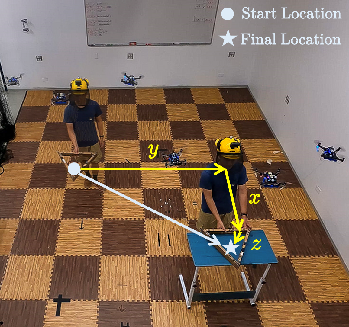
In this experiment, the robot team and the human operator collaborate together to move a payload from the starting location to the final location via direct force interaction. Payload translates in all three axes, as shown in Fig. 9. The square gain matrices are selected block-diagonal as .
Note that the spring constant coefficient for the admittance controller is set to zero so that the payload stays at the position/orientation once the human operator releases the payload.
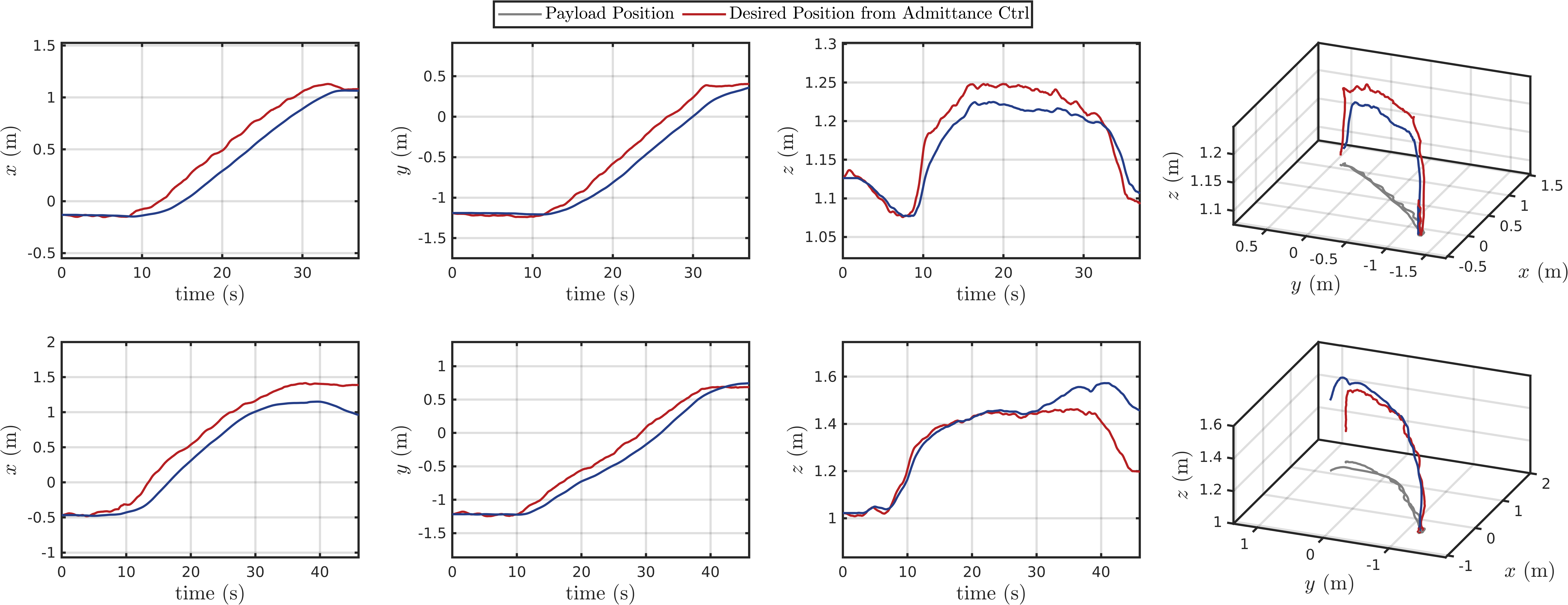
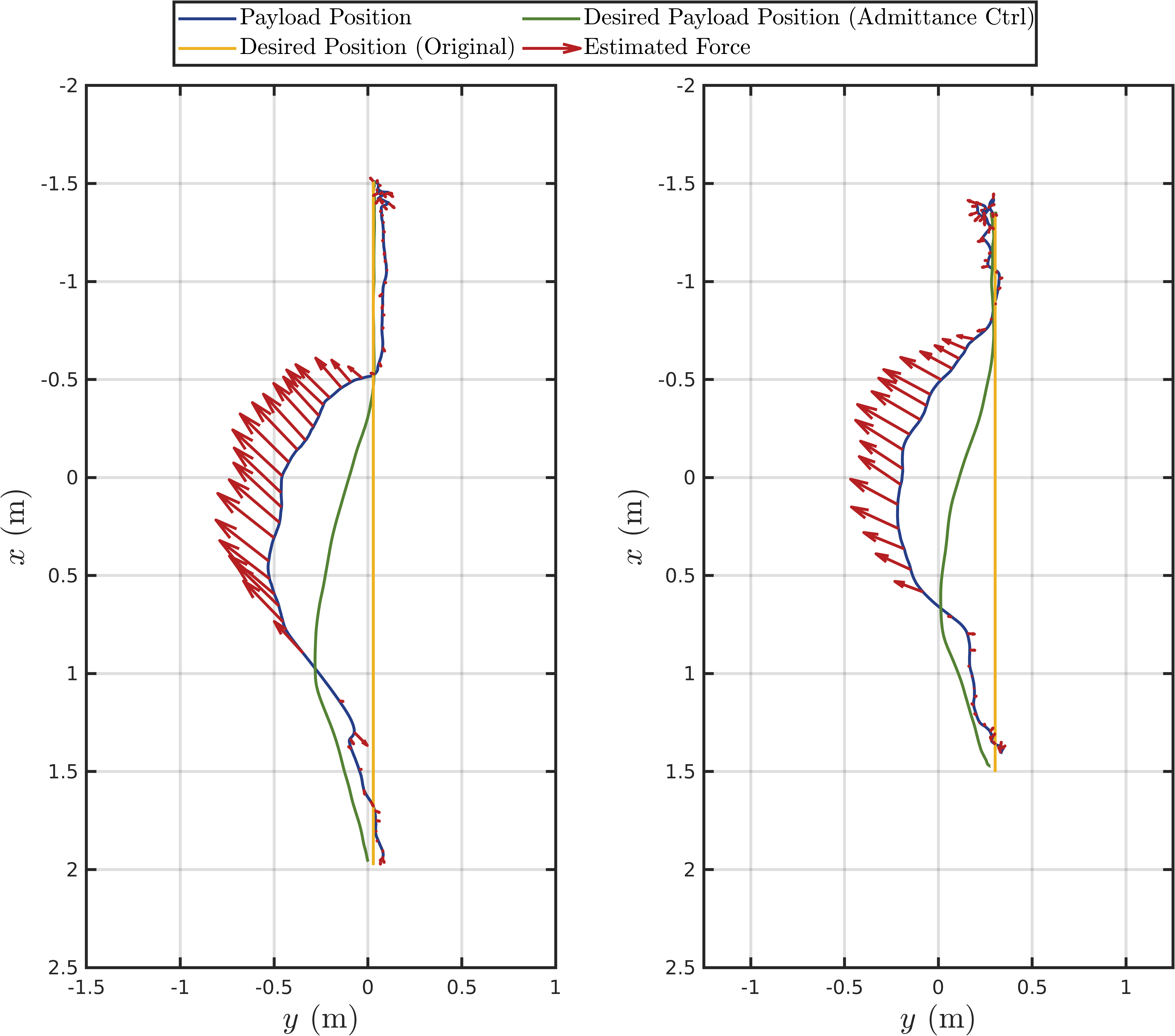
The experimental results are shown in Fig. 10, where we compare the actual payload position with desired payload position from the admittance controller.
The results demonstrate the proposed methods can confidently update the desired payload position to satisfy the human operator’s intention of moving the payload under both gradient-based and optimization-based human safety methods. Furthermore, the movement introduced by the null-space-based safety controller does not affect the performance of the payload wrench estimation or admittance controller.
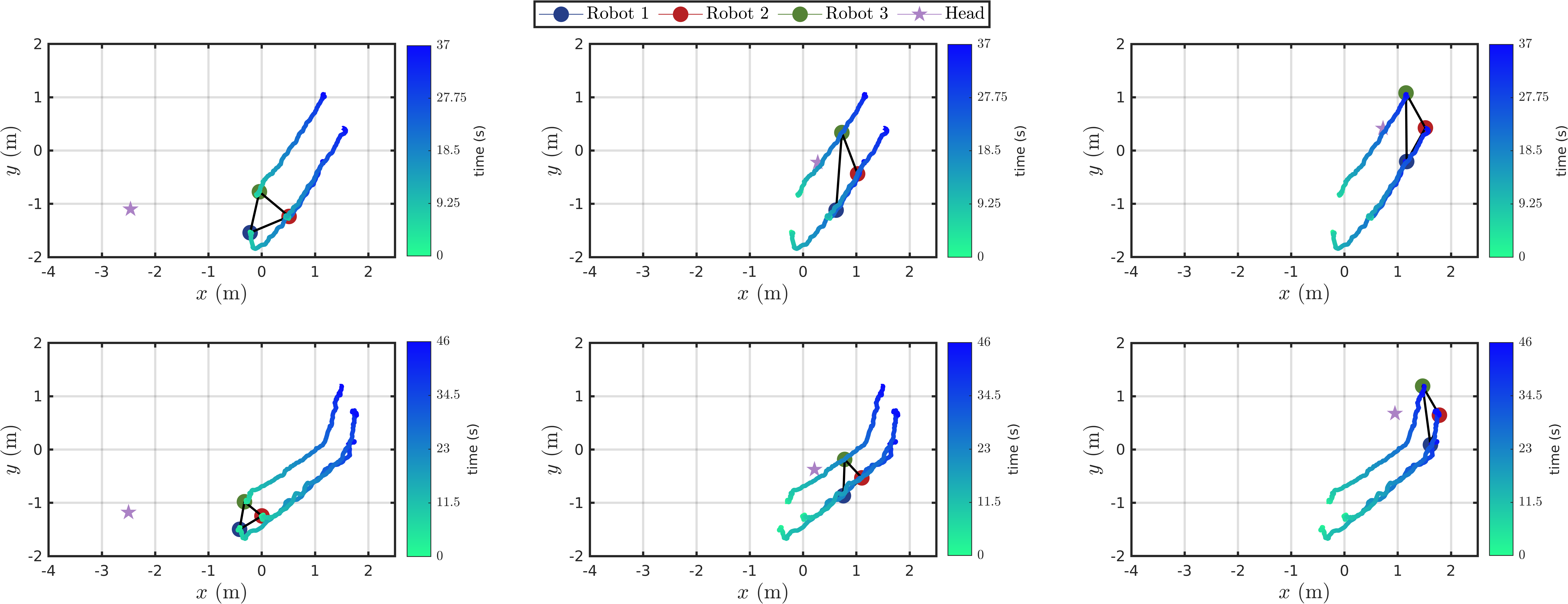
In Fig. 11, we show the effects of the two human-safety-aware controllers with a top view of the entire collaboration task. From the plots, we can observe that, as the human operator, denoted by the purple star, approaches the robots with a suspended payload, the human-safety-aware controllers start to be effective. The controller expands the robots (blue and green circles) that are close to the human operator to keep the distance.
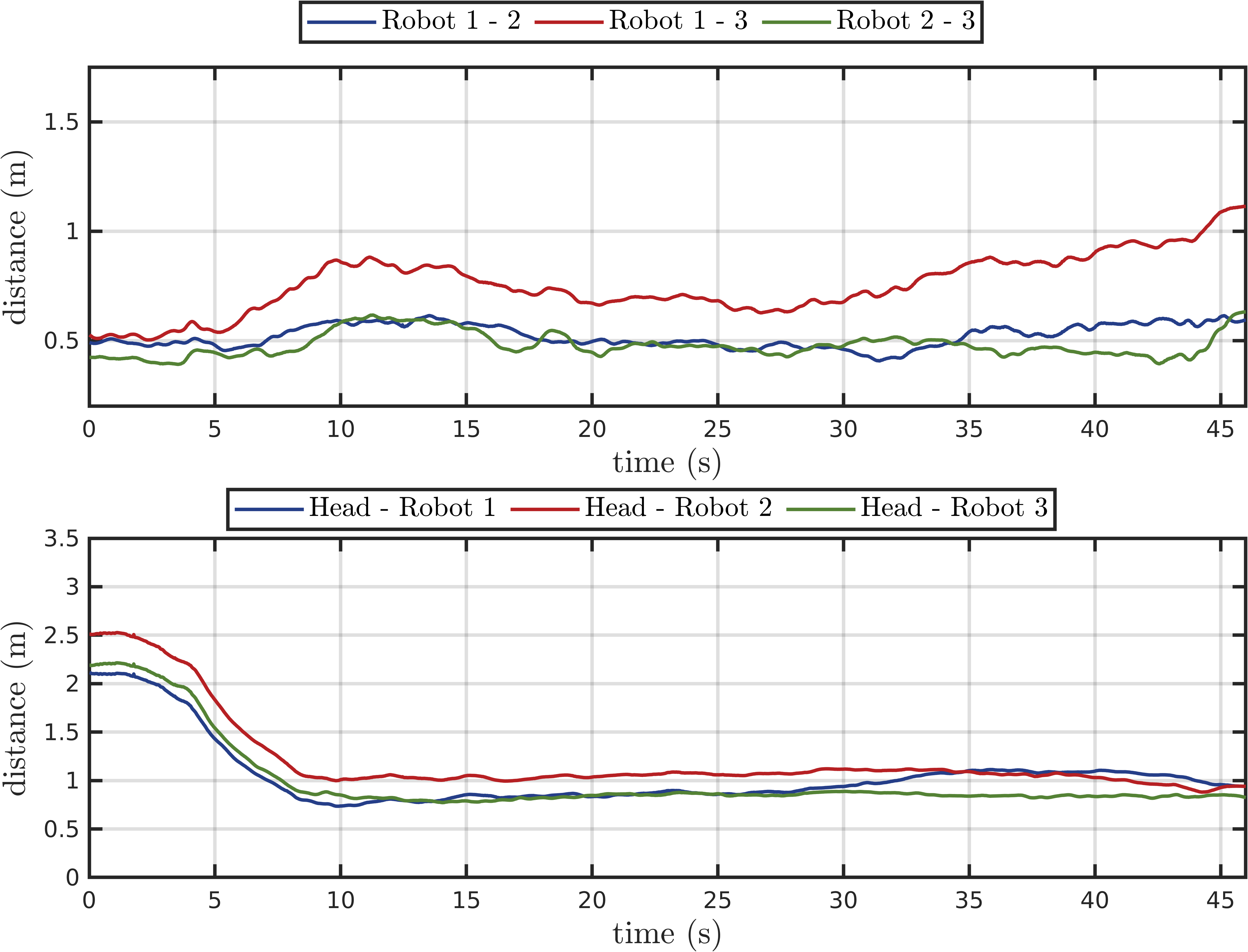
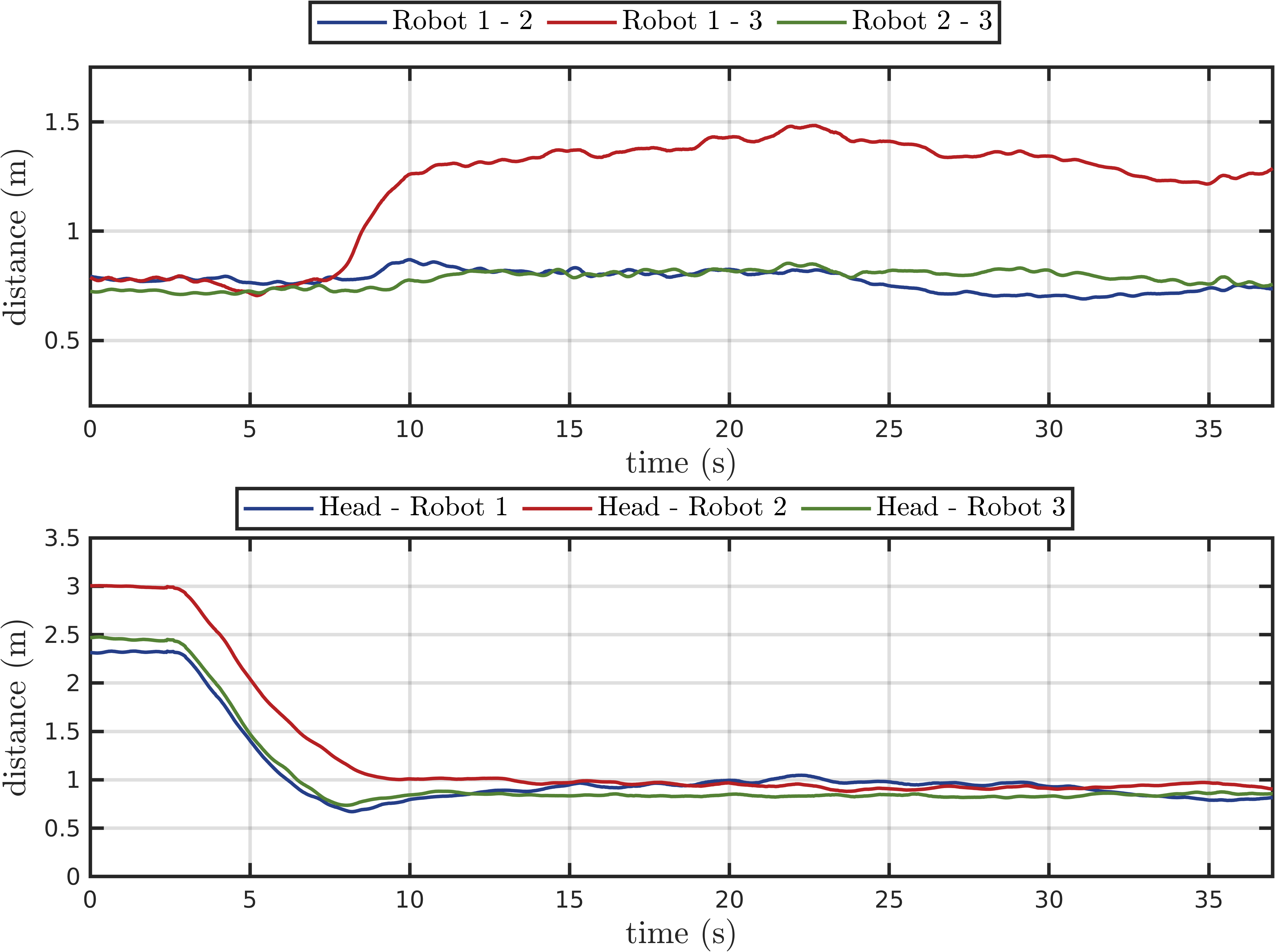
To further support our analysis with quantitative results, we plot the distances between each drone with the human operator and one another in Figs. 12 and 13 throughout the entire tasks. First, from both figures, we can see that the human operator starts about away from the robot team. As the human operator approaches the robot team, the distances between the human operator and the robot 1 and 3 (denoted by blue and green) reduce to around . Then the safety-aware controllers, both optimization-based and gradient-based methods, start to be effective and maintain the human-robot distance around the boundary. Both methods generate sufficient distance between the human operator and drones to give the human operator confidence and a sense of security when interacting with the payload.
Additionally, we would like to point out that the optimization-based method differs from the gradient-based method in that it allows safety distance to be implemented between drones. In the top plot in Fig. 13, all three drones are keeping at least or more than safe distance from each other as the constraints require the inter-robot distance should be larger than or equal to .
| Scalability | Time Complexity | |
| \cellcolormygreenHuman Interaction | \cellcolormygreen | \cellcolormygreen |
| Quadrotor Estimation | High | |
| Payload Wrench Estimation | Medium | |
| Payload Admittance Controller | High | |
| \cellcolormybluePlanning and Control | \cellcolormyblue | \cellcolormyblue |
| Payload Trajectory Planner | High | |
| Payload Trajectory Tracking Controller | High | |
| Tension Distribution | Medium / High | Exp: / Theory: |
| Gradient-Based Safety Controller | High | |
| Optimization-Based Safety Controller | Low | |
| Quadrotor Controller | High |
VI-C2 Human-assisted Payload Trajectory Tracking
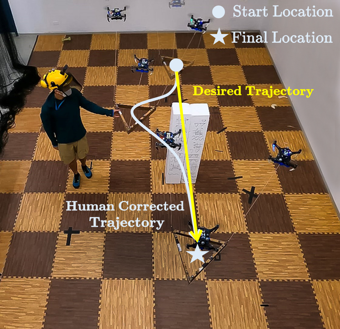
In this experiment, the payload follows a straight trajectory from the starting location to the final location, as the robot team is unaware of the obstacle. The human operator corrects the payload trajectory to avoid the obstacle, as shown in Fig. 14. Both gradient-based and optimization-based methods are also applied here. The square gain matrices for the admittance controller have a block-diagonal structure as .
Note that the constant spring coefficient for the admittance controller is no longer zero. The payload will now return to the position/orientation commanded by the trajectory when the human operator releases the payload.
As we can see from Fig. 15, the correction takes effects according to the admittance controlled trajectory. Once the human operator stops the correction, the non-zero constant starts to allow the corrected trajectory to converge with the original trajectory. As expected, such behavior is present in both the gradient-based and optimization-based methods.
VII Discussion
VII-A Scalability
Our approach is designed in a way that both distributed and centralized computations can be performed. In this section, we discuss the scalability of our proposed algorithms and we summarize the results in Table III.
VII-A1 Human Interaction
In the estimation part of the Human Interaction module, each quadrotor runs its own quadrotor estimation onboard, which is independent of the number of quadrotors in the system.
Next, the payload wrench estimation computation can operate on a central ground station or on each of the quadrotor in a distributed fashion as the team synchronizes their clocks and share the individual cable force estimation among the team. The computation, as shown in eq. (36), scales linearly with the number of quadrotors because of the linear tension mapping matrix . The computation complexity in eq. (36) is bounded by , where represents the number of quadrotors within the system. This is because the dimension of matrix , as depicted in eq. (2), scales in accordance with . Linear time complexity is not a problem based on the available computational resource since has to be in the order of thousands in order to have this linear-complexity matrix multiplication be the bottleneck of the system.
Similarly, the payload admittance controller in eq. (37) can operate on a central ground station or on each of the quadrotor in a distributed fashion as the team synchronizes their clocks. Its computation is independent of the number of quadrotors in the system because the payload admittance controller controls only the DoFs of the payload.
VII-A2 Planning and Control
On the Planning and Control side, the payload trajectory planner and trajectory tracking controller can operate in the same fashion as the admittance controller. This means that they can either run on the ground station or each of the quadrotor with the quadrotors synchronizing with each other using synchronization software like Chrony. Its computation is independent of the number of quadrotors. The quadrotor controllers in eqs. (25) and (26) operate in a distributed fashion on each quadrotor.
The tension distribution requires a linear mapping in the form of matrix multiplication as shown in eq. (9) and has a bounded complexity of where is the number of quadrotors in the system. It is possible to distribute this linear mapping computation: store blocks of the pseudoinverse of the tension distribution matrix in each drone and perform the tension mapping computation onboard each drone. This would reduce the complexity to .
Regarding the human-safety-aware controller, it could operate in a centralized fashion or a distributed fashion depending on the chosen method. The following two paragraphs discuss the two methods
-
i)
If the optimization-based safety controller is used, the sequential quadratic programming solver requires storage and time, where is the dimension of the problem. The solver runs in a centralized fashion and the required computation scales up cubically.
-
ii)
If the gradient-based safety controller is used, the tension modifier term could be computed onboard each quadrotor. In the gradient-based safety controller, the tension modifier is computed using the null space projection of a scaled gradient vector that maximizes eq. (15), which is the sum of the -norm distances of each quadrotor and the human operator. The closed-form gradient with respect to each quadrotor is provided in eq. (16). The null space projection can be written as the optimization in eq. (18), which has the closed form solution eq. (19). The tension modifier that each quadrotor needs can be computed on each quadrotor. Computation time and space complexity are independent of the number of quadrotors due to the usage of closed-form solutions for both gradient computation and null space projection computation. The gradient-based safety controller runs in a distributed manner.
In conclusion, considering the overall scalability, only when the optimization-based safety controller is used, will the system become centralized, and its scalability on the controller side may be affected. Conversely, the system is more scalable with the gradient-based safety controller.
VII-B Potential of Using Onboard Sensing and Perception
Throughout this paper, we employ a motion capture system for multiple purposes:
-
i)
providing feedback on the payload states (pose and velocity) to the controller;
-
ii)
supplying measurement updates on the drone and cable states for the UKF on each drone, where the UKF utilizes motor speeds and a nonlinear dynamics model to predict drone states, including the tension force vector, without using force sensors;
-
iii)
and providing the position of the human operator in the world.
We argue that the state estimation can be replaced with onboard sensing due to several reasons. As discussed in [11], we designed an Extended Kalman Filter (EKF) to predict the cable direction and velocity through the nonlinear dynamics model using the IMU data and motor speeds from the Electronic Speed Controller (ESC). By employing a black-and-white circular tag attached at each cable’s end and applying the computer vision algorithm from [66], we can obtain the measurement of the attach point position with respect to the robot frame at Hz camera rate. Given the assumption that the cable remains taut, we can leverage the geometry constraints and the robot’s orientation estimated by the onboard Visual-Inertial Odometry (VIO) algorithm to measure the cable’s direction with respect to the world frame. The measured cable direction above serves as a measurement update to the EKF, ensuring our estimate remains accurate and responsive. With the proposed EKF estimator, we can obtain the cable direction and velocity up to 250 Hz.
Furthermore, we can also leverage the quadrotor position estimated from the onboard VIO and the estimated cable direction from above, under the taut cable assumption, to infer the attach point position in the world frame. By sharing the positions of all attach points among the robots, they can collectively estimate the payload state, pose, and velocity, which can then be used as feedback for the payload controller.
In [11], we validate the vision-based state estimation method by comparing the states from the onboard estimation system with those obtained from the motion capture system. The results indicate that the onboard estimation system provides comparable outcomes to the motion capture system, with only cm-level errors. Hence, this technique can potentially provide all necessary measurement updates for the UKF developed in this paper. Finally, theoretically, we can also obtain the position of the human using onboard cameras by leveraging state-of-the-art human pose estimators [65].
VIII Conclusion and Future Works
In this paper, we presented a safety-aware human-robot collaborative transportation and manipulation approach considering a team of aerial robots with a cable-suspended payload. Our approach allows a human operator to interact in DoF with a rigid structure transported through the cable by a team of aerial robots. Additionally, the system incorporates important safety requirements by exploiting the additional system redundancy. We demonstrated, through real-world experiments, our system’s capability to keep a safe distance from the human operator and between each agent without affecting the quality or accuracy of the interactive experience. The system can assist the human during a complex and heavy manipulation task and enable the human operator to complement the load navigation presented in the obstacle avoidance experiment.
Future work could incorporate human-centric studies, focusing on human-related metrics such as the comfort and acceptance of the approach by the human operator, which are pivotal factors in the realm of human-robot interaction. Moreover, enhancing safety measures against unforeseen human actions such as abrupt or forceful pulling of the load, which could cause the cable to slack or exceed the actuator’s limits, will also be of critical importance.
We would also like to incorporate the tension-measurement device onboard each MAV to provide additional accuracy in the tension estimation process. Furthermore, we would also like to introduce an obstacle-detection module. As a result, the robot team can identify potential hazardous volumes in space using onboard computation. Subsequently, we can utilize the null space to autonomously avoid any drone getting close to such volume without affecting payload trajectory tracking. Finally, another potential future work will be applying deep-learning-based methods with the robots’ onboard cameras to estimate the human operator’s pose as input to the proposed safety-aware controller.
References
- [1] K. Schwab, The fourth industrial revolution. London, England: Portfolio Penguin, 2017.
- [2] S. S. Mansouri, C. Kanellakis, E. Fresk, D. Kominiak, and G. Nikolakopoulos, “Cooperative coverage path planning for visual inspection,” Control Engineering Practice, vol. 74, pp. 118–131, May 2018.
- [3] K. Shah, G. Ballard, A. Schmidt, and M. Schwager, “Multidrone aerial surveys of penguin colonies in antarctica,” Science Robotics, vol. 5, no. 47, p. eabc3000, 2020.
- [4] G. Loianno, Y. Mulgaonkar, C. Brunner, D. Ahuja, A. Ramanandan, M. Chari, S. Diaz, and V. Kumar, “Autonomous flight and cooperative control for reconstruction using aerial robots powered by smartphones,” The International Journal of Robotics Research, vol. 37, no. 11, pp. 1341–1358, 2018.
- [5] N. Michael, S. Shen, K. Mohta, Y. Mulgaonkar, V. Kumar, K. Nagatani, Y. Okada, S. Kiribayashi, K. Otake, K. Yoshida, K. Ohno, E. Takeuchi, and S. Tadokoro, “Collaborative mapping of an earthquake-damaged building via ground and aerial robots,” Journal of Field Robotics, vol. 29, no. 5, pp. 832–841, 2012.
- [6] A. E. Jiménez-Cano, D. Sanalitro, M. Tognon, A. Franchi, and J. Cortés, “Precise cable-suspended pick-and-place with an aerial multi-robot system: A proof of concept for novel robotics-based construction techniques,” Journal of Intelligent & Robotic Systems, vol. 105, no. 3, p. 68, Jul. 2022.
- [7] D. Sanalitro, M. Tognon, A. J. Cano, J. Cortés, and A. Franchi, “Indirect force control of a cable-suspended aerial multi-robot manipulator,” IEEE Robotics and Automation Letters, vol. 7, no. 3, pp. 6726–6733, 2022.
- [8] M. Saska, V. Vonásek, J. Chudoba, J. Thomas, G. Loianno, and V. Kumar, “Swarm distribution and deployment for cooperative surveillance by micro-aerial vehicles,” Journal of Intelligent & Robotic Systems, vol. 84, no. 1, pp. 469–492, Dec. 2016.
- [9] G. Li and G. Loianno, “Design and experimental evaluation of distributed cooperative transportation of cable suspended payloads with micro aerial vehicles,” in Experimental Robotics, B. Siciliano, C. Laschi, and O. Khatib, Eds. Cham: Springer International Publishing, 2021, pp. 28–36.
- [10] B. E. Jackson, T. A. Howell, K. Shah, M. Schwager, and Z. Manchester, “Scalable cooperative transport of cable-suspended loads with UAVs using distributed trajectory optimization,” IEEE Robotics and Automation Letters, vol. 5, no. 2, pp. 3368–3374, 2020.
- [11] G. Li, R. Ge, and G. Loianno, “Cooperative transportation of cable suspended payloads with MAVs using monocular vision and inertial sensing,” IEEE Robotics and Automation Letters, vol. 6, no. 3, pp. 5316–5323, 2021.
- [12] A. Ollero, M. Tognon, A. Suarez, D. Lee, and A. Franchi, “Past, present, and future of aerial robotic manipulators,” IEEE Transactions on Robotics, vol. 38, no. 1, pp. 626–645, 2022.
- [13] A. Tagliabue, M. Kamel, S. Verling, R. Siegwart, and J. Nieto, “Collaborative transportation using mavs via passive force control,” in IEEE International Conference on Robotics and Automation (ICRA), 2017, pp. 5766–5773.
- [14] G. Loianno and V. Kumar, “Cooperative transportation using small quadrotors using monocular vision and inertial sensing,” IEEE Robotics and Automation Letters, vol. 3, no. 2, pp. 680–687, April 2018.
- [15] D. Mellinger, M. Shomin, N. Michael, and V. Kumar, Cooperative Grasping and Transport Using Multiple Quadrotors. Berlin, Heidelberg: Springer Berlin Heidelberg, 2013, pp. 545–558.
- [16] J. Thomas, G. Loianno, J. Polin, K. Sreenath, and V. Kumar, “Toward autonomous avian-inspired grasping for micro aerial vehicles,” Bioinspiration & biomimetics, vol. 9, no. 2, p. 025010, 2014.
- [17] A. Afifi, M. van Holland, and A. Franchi, “Toward physical human-robot interaction control with aerial manipulators: Compliance, redundancy resolution, and input limits,” in IEEE International Conference on Robotics and Automation (ICRA), 2022, pp. 4855–4861.
- [18] G. Corsini, M. Jacquet, H. Das, A. Afifi, D. Sidobre, and A. Franchi, “Nonlinear model predictive control for human-robot handover with application to the aerial case,” in IEEE/RSJ International Conference on Intelligent Robots and Systems (IROS), Kyoto, Japan, Oct. 2022.
- [19] M. Tognon, R. Alami, and B. Siciliano, “Physical human-robot interaction with a tethered aerial vehicle: Application to a force-based human guiding problem,” IEEE Transactions on Robotics, vol. 37, no. 3, pp. 723–734, 2021.
- [20] J. Lee, R. Balachandran, Y. S. Sarkisov, M. De Stefano, A. Coelho, K. Shinde, M. J. Kim, R. Triebel, and K. Kondak, “Visual-inertial telepresence for aerial manipulation,” in IEEE International Conference on Robotics and Automation (ICRA), 2020, pp. 1222–1229.
- [21] J. Geng and J. Langelaan, “Cooperative transport of a slung load using load-leading control,” Journal of Guidance, Control, and Dynamics, vol. 43, no. 7, pp. 1313–1331, 2020.
- [22] H. Rastgoftar and E. M. Atkins, “Cooperative aerial payload transport guided by an in situ human supervisor,” IEEE Transactions on Control Systems Technology, vol. 27, no. 4, pp. 1452–1467, Jul. 2019.
- [23] M. Romano, A. Ye, J. Pye, and E. Atkins, “Cooperative multilift slung load transportation using haptic admittance control guidance,” Journal of Guidance, Control, and Dynamics, vol. 45, no. 10, pp. 1899–1912, 2022.
- [24] K. Klausen, C. Meissen, T. I. Fossen, M. Arcak, and T. A. Johansen, “Cooperative control for multirotors transporting an unknown suspended load under environmental disturbances,” IEEE Transactions on Control Systems Technology, vol. 28, no. 2, pp. 653–660, 2020.
- [25] M. Bernard, K. Kondak, I. Maza, and A. Ollero, “Autonomous transportation and deployment with aerial robots for search and rescue missions,” Journal of Field Robotics, vol. 28, no. 6, pp. 914–931, 2011.
- [26] V. P. Tran, F. Santoso, M. A. Garratt, and S. G. Anavatti, “Distributed artificial neural networks-based adaptive strictly negative imaginary formation controllers for unmanned aerial vehicles in time-varying environments,” IEEE Transactions on Industrial Informatics, vol. 17, no. 6, pp. 3910–3919, 2021.
- [27] X. Zhang, F. Zhang, P. Huang, J. Gao, H. Yu, C. Pei, and Y. Zhang, “Self-triggered based coordinate control with low communication for tethered multi-uav collaborative transportation,” IEEE Robotics and Automation Letters, vol. 6, no. 2, pp. 1559–1566, 2021.
- [28] Y. Liu, F. Zhang, P. Huang, and X. Zhang, “Analysis, planning and control for cooperative transportation of tethered multi-rotor UAVs,” Aerospace Science and Technology, vol. 113, p. 106673, 2021.
- [29] T. Lee, K. Sreenath, and V. Kumar, “Geometric control of cooperating multiple quadrotor UAVs with a suspended payload,” in 52nd IEEE Conference on Decision and Control (CDC), 2013, pp. 5510–5515.
- [30] M. Gassner, T. Cieslewski, and D. Scaramuzza, “Dynamic collaboration without communication: Vision-based cable-suspended load transport with two quadrotors,” in IEEE International Conference on Robotics and Automation (ICRA), 2017, pp. 5196–5202.
- [31] H. Rastgoftar and E. M. Atkins, “Continuum deformation of a multiple quadcopter payload delivery team without inter-agent communication,” in International Conference on Unmanned Aircraft Systems (ICUAS), 2018, pp. 539–548.
- [32] H. Xie, K. Dong, and P. Chirarattananon, “Cooperative transport of a suspended payload via two aerial robots with inertial sensing,” IEEE Access, vol. 10, pp. 81 764–81 776, 2022.
- [33] A. Tagliabue, M. Kamel, R. Siegwart, and J. Nieto, “Robust collaborative object transportation using multiple MAVs,” The International Journal of Robotics Research, vol. 38, no. 9, pp. 1020–1044, 2019.
- [34] T. Lee, “Geometric control of quadrotor UAVs transporting a cable-suspended rigid body,” IEEE Transactions on Control Systems Technology, vol. 26, no. 1, pp. 255–264, 2018.
- [35] G. Wu and K. Sreenath, “Geometric control of multiple quadrotors transporting a rigid-body load,” in 53rd IEEE Conference on Decision and Control (CDC). IEEE, 2014, pp. 6141–6148.
- [36] J. Fink, N. Michael, S. Kim, and V. Kumar, “Planning and control for cooperative manipulation and transportation with aerial robots,” The International Journal of Robotics Research, vol. 30, no. 3, pp. 324–334, 2011.
- [37] N. Michael, J. Fink, and V. Kumar, “Cooperative manipulation and transportation with aerial robots,” Autonomous Robots, vol. 30, no. 1, pp. 73–86, Jan 2011.
- [38] R. C. Sundin, P. Roque, and D. V. Dimarogonas, “Decentralized model predictive control for equilibrium-based collaborative uav bar transportation,” in IEEE International Conference on Robotics and Automation (ICRA), 2022, pp. 4915–4921.
- [39] G. Tartaglione, E. D’Amato, M. Ariola, P. S. Rossi, and T. A. Johansen, “Model predictive control for a multi-body slung-load system,” Robotics and Autonomous Systems, vol. 92, pp. 1–11, Jun. 2017.
- [40] T. Lee, “Geometric control of multiple quadrotor UAVs transporting a cable-suspended rigid body,” in 53rd IEEE Conference on Decision and Control (CDC), 2014, pp. 6155–6160.
- [41] J. Geng, P. Singla, and J. W. Langelaan, “Load-distribution-based trajectory planning and control for a multilift system,” Journal of Aerospace Information Systems, vol. 19, no. 5, pp. 366–381, 2022.
- [42] C. Masone, H. H. Bülthoff, and P. Stegagno, “Cooperative transportation of a payload using quadrotors: A reconfigurable cable-driven parallel robot,” in IEEE/RSJ International Conference on Intelligent Robots and Systems (IROS), 2016, pp. 1623–1630.
- [43] E. Bulka, C. He, J. Wehbeh, and I. Sharf, “Experiments on collaborative transport of cable-suspended payload with quadrotor UAVs,” in International Conference on Unmanned Aircraft Systems (ICUAS), 2022, pp. 1465–1473.
- [44] L. v. der Spaa, M. Gienger, T. Bates, and J. Kober, “Predicting and optimizing ergonomics in physical human-robot cooperation tasks,” in IEEE International Conference on Robotics and Automation (ICRA), 2020, pp. 1799–1805.
- [45] J. Stuckler and S. Behnke, “Following human guidance to cooperatively carry a large object,” in 11th IEEE-RAS International Conference on Humanoid Robots, Bled, Slovenia, Oct 2011, p. 218–223.
- [46] M. Gienger, D. Ruiken, T. Bates, M. Regaieg, M. MeiBner, J. Kober, P. Seiwald, and A.-C. Hildebrandt, “Human-robot cooperative object manipulation with contact changes,” in IEEE/RSJ International Conference on Intelligent Robots and Systems (IROS), 2018, pp. 1354–1360.
- [47] W. Sheng, A. Thobbi, and Y. Gu, “An integrated framework for human–robot collaborative manipulation,” IEEE Transactions on Cybernetics, vol. 45, no. 10, p. 2030–2041, Oct 2015.
- [48] F. Augugliaro and R. D’Andrea, “Admittance control for physical human-quadrocopter interaction,” in 2013 European Control Conference (ECC), Jul 2013, p. 1805–1810.
- [49] D. Sieber, S. Musić, and S. Hirche, “Multi-robot manipulation controlled by a human with haptic feedback,” in IEEE/RSJ International Conference on Intelligent Robots and Systems (IROS), Sep 2015, p. 2440–2446.
- [50] G. A. Yashin, D. Trinitatova, R. T. Agishev, R. Ibrahimov, and D. Tsetserukou, “Aerovr: Virtual reality-based teleoperation with tactile feedback for aerial manipulation,” in 2019 19th International Conference on Advanced Robotics (ICAR), Dec 2019, p. 767–772.
- [51] S. O. Sachidanandam, S. Honarvar, and Y. Diaz-Mercado, “Effectiveness of augmented reality for human swarm interactions,” in 2022 International Conference on Robotics and Automation (ICRA), May 2022, p. 11258–11264.
- [52] M. L. Elwin, B. Strong, R. A. Freeman, and K. M. Lynch, “Human-multirobot collaborative mobile manipulation: The omnid mocobots,” IEEE Robotics and Automation Letters, vol. 8, no. 1, p. 376–383, Jan 2023.
- [53] D. Sirintuna, I. Ozdamar, and A. Ajoudani, “Carrying the uncarriable: a deformation-agnostic and human-cooperative framework for unwieldy objects using multiple robots,” in IEEE International Conference on Robotics and Automation (ICRA), 2023, pp. 4915–4921.
- [54] N. E. Carey and J. Werfel, “A force-mediated controller for cooperative object manipulation with independent autonomous robots,” in International Symposium on Distributed Autonomous Robotic Systems, 2022.
- [55] P. A. Lasota, T. Fong, and J. A. Shah, “A survey of methods for safe human-robot interaction,” Foundations and Trends in Robotics, vol. 5, no. 3, p. 261–349, 2017.
- [56] B. Siciliano, L. Sciavicco, L. Villani, and G. Oriolo, Robotics Modelling, Planning and Control. Springer London, 2009.
- [57] D. Bertsekas, Nonlinear Programming. Athena Scientific, 1999.
- [58] D. Kraft, “Algorithm 733: Tomp–fortran modules for optimal control calculations,” ACM Trans. Math. Softw., vol. 20, no. 3, p. 262–281, sep 1994.
- [59] S. G. Johnson, The NLopt nonlinear-optimization package, 2011. [Online]. Available: http://ab-initio.mit.edu/nlopt
- [60] D. Mellinger and V. Kumar, “Minimum snap trajectory generation and control for quadrotors,” in IEEE International Conference on Robotics and Automation (ICRA), 2011, pp. 2520–2525.
- [61] J. Sola, “Quaternion kinematics for the error-state kalman filter,” arXiv preprint arXiv:1711.02508, 2017.
- [62] S. Thrun, W. Burgard, and D. Fox, Probabilistic Robotics. MIT Press, 2005.
- [63] G. Loianno, C. Brunner, G. McGrath, and V. Kumar, “Estimation, control, and planning for aggressive flight with a small quadrotor with a single camera and imu,” IEEE Robotics and Automation Letters, vol. 2, no. 2, pp. 404–411, April 2017.
- [64] G. Li, X. Liu, and G. Loianno, “RotorTM: A flexible simulator for aerial transportation and manipulation,” 2022. [Online]. Available: https://arxiv.org/abs/2205.05140
- [65] S. Ren, K. He, R. Girshick, and J. Sun, “Faster R-CNN: Towards real-time object detection with region proposal networks,” in Advances in Neural Information Processing Systems, C. Cortes, N. Lawrence, D. Lee, M. Sugiyama, and R. Garnett, Eds., vol. 28. Curran Associates, Inc., 2015.
- [66] T. Krajník, M. Nitsche, J. Faigl, P. Vaněk, M. Saska, L. Přeučil, T. Duckett, and M. Mejail, “A practical multirobot localization system,” Journal of Intelligent & Robotic Systems, vol. 76, pp. 539–562, 2014.