Update on the LLRF operations status at the European XFEL
Abstract
The European XFEL (EuXFEL) is a free-electron laser in the X-ray range for users. Its high availability is one of the key aspects of the machine. In 2022, it entered in the sixth year of operation. The EuXFEL linac is based on the TESLA superconducting RF technology, operating at 1.3 GHz with an RF pulse length of and a repetition rate of 10 Hz. The LLRF system is based on the MicroTCA standard and relies on a high level of automation. In this contribution, we review the LLRF operation at the EuXFEL and the development of new tools and features to improve the monitoring and extend the usability of the LLRF system.
1 THE EUROPEAN XFEL
The European XFEL is a hard X-ray free-electron laser (FEL) based on a high-electron-energy superconducting linear accelerator [Decking2020AAccelerator]. With different linac energies ranging from 8 to 17.5 GeV and variable-gap undulators, photon energies from 0.25 to 25 keV can be covered.
The baseline frequency of the RF system is 1.3 GHz. The linac is made up of a normal conducting gun followed by an accelerating module (named A1) and a third harmonic lineariser module (called AH1) operating at 3.9 GHz. The linac is then completed by other 24 RF stations (A2-A25), each of them fed by one 10 MW multibeam klystron [Bousonville2021EuropeanOperation]. The regular RF station is made up of 4 cryomodules (with the exception of A1 and AH1 that have only one accelerating module each), where every module is made up of 8 standing wave superconducting TESLA cavities [Aune2000SuperconductingCavities].
The multicavity LLRF system is based on the MicroTCA.4 standard (MTCA). It provides RMS field stability better than 0.01% in amplitude and 0.01 deg in phase at the 1.3 GHz cavity operating frequency [Branlard2012TheSystem]. For every regular RF station, it is split into manager and subordinate crates as each of them can process the signals from up to 2 cryomodules. For this reason, A1 and AH1 can share the same MTCA crate.
2 LLRF STATISTICS
At the EuXFEL, there are currently 4 reference energy settings: 8, 11.5, 14 and 16.3 GeV. The first three are comprised in the so-called "reduced-energy configuration (RE)", while the latter in the "high-energy configuration (HE)". The differences between the two configurations are the modulator high-voltage of some RF stations and the average gradient in the cavities. Switching between the three beam energies of the reduced-energy configuration is done by changing the off-crest RF phase by means of the Linac Energy Manager server [Hensler2017RF-EnergyXFEL].
Running at high-energy implies a higher accelerating gradient in the cavities, a higher dark current radiation and then a higher incidence of Single Event Upsets (SEUs) that can affect the MTCA boards, causing station trips.
In order to maintain the full functionality of the LLRF system, a weekly maintenance is performed every Monday for 1 hour. Due to the complexity and extension of the LLRF system at the EuXFEL, having it always in nominal running condition (i.e. every single aspect of it at the desired status or setting) might be not easy. Most important properties of the LLRF system that are regularly checked in order to guarantee full functionality comprise: status of the cavity tuners and RF power coupler motors, resonance frequency of the cavities and loaded quality factor (), status of the tuning piezos, reference phase, status of the MTCA crates, LLRF feedbacks, cavity power limiters, quench protection, drift compensation modules, control system servers, power supplies of the racks, etc… Thus, typical operations during weekly maintenance include:
-
•
Power-cycle of faulty MTCA boards, CPUs, crates;
-
•
Piezo relaxation (reduction of piezo DC voltage to extend their lifetime);
-
•
adjustment;
-
•
Beam based calibration.
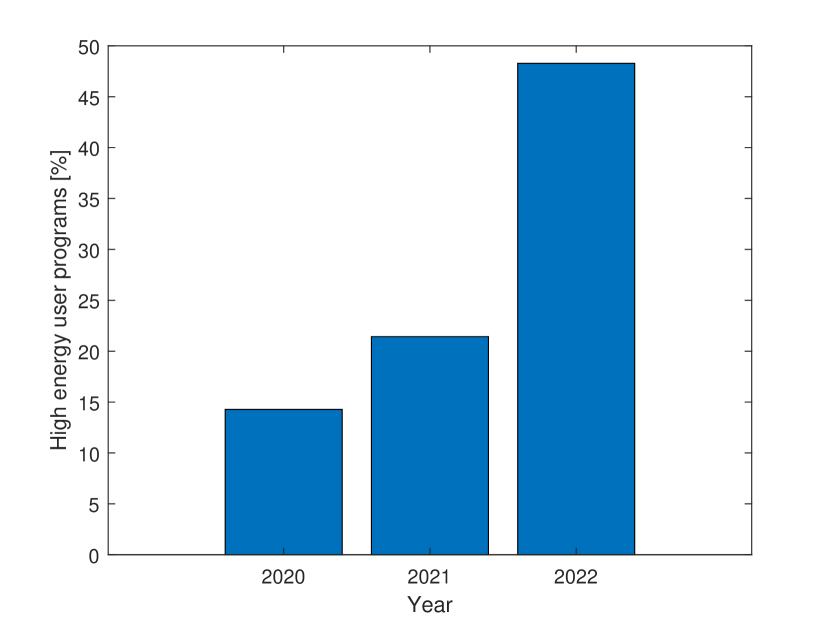
The 16.3 GeV energy is highly requested by the FEL users. Indeed, in 2022, EuXFEL will run at high-energy for almost 50% of the user time (Fig. 1).
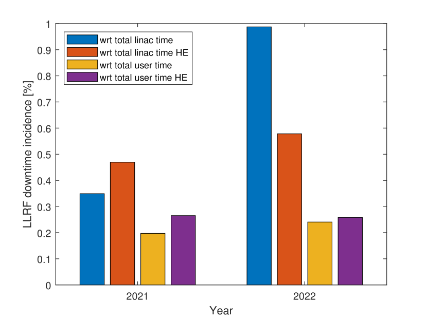
In Table 1 and Fig. 2, the LLRF downtime incidence with respect to the total linac time and total user time is shown. In addition to the user time, the total linac time is given by setup, tuning and facility development time. From the statistics, it is possible to observe that running in high-energy increases the contribution of the LLRF system to the total linac downtime. Nevertheless, during user time, this contribution is limited to a value that is lower than 0.3%. A very good result, considering the total length of the linac and the radiation prone environment (the racks are located underneath the cryomodules in the same tunnel). During reduced-energy runs, it is possible to perform tests on a few RF stations placing them "off-beam", i.e. shifting their timing with respect to beam. These studies allow to discover field emitters and quenching cavities. The solution applied in these cases is to reduce the maximum voltage of the affected RF station or to detune the affected cavity.
| Year | Total linac time [days] | Total LLRF downtime [hours] | Total user time [days] | User LLRF downtime [hours] | User HE weeks |
| 2021 | 277.36 | 23.23 | 168.00 | 7.94 | 6 |
| 2022 | 236.21 | 55.97 | 136.00 | 7.86 | 14 |
3 NEW TOOLS AND FEATURES
Due to the large scale of the accelerator, a high degree of automation is provided to assist operators and system experts, including exception detection and handling. In the past months, several new tools and features have been introduced at the EuXFEL to further improve the monitoring and extend the usability of the LLRF system.
3.1 LLRF status tool
As mentioned in the previous section, maintenance of the LLRF system is regularly performed. Having an instantaneous picture of such a complex and distributed system is very helpful. Including in a single jddd (Java Data Display program for the Distributed Object Oriented Control System) [Sombrowski2007JDDD:XFEL] panel information about the status of MTCA crates, LLRF controllers and servers, cavity signals, external hardware units, coupler and cavity tuners is almost impossible. For this reason, a MATLAB script has been developed to check hundreds of Distributed Object Oriented Control System (DOOCS) ([Grygiel1996DOOCS:Workstations]) properties in about 30 seconds. By means of the GUI, it is also possible to check a reduced number of properties grouped by LLRF subsystem and obtain a quicker output. The tool generates a textual report and the run of the script is daily scheduled through cron jobs with automatic emails sent to the experts. This tool allows to have an updated status of the system so that everything can be fixed during maintenance time.
3.2 Cavity tuner tool
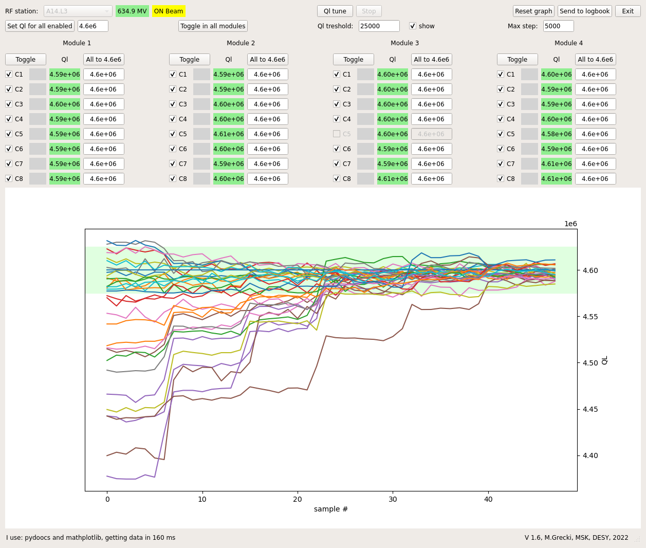
A new cavity tuner Python script has been recently developed and deployed at the EuXFEL. As already mentioned in the previous section, the adjustment is part of the activities performed during LLRF maintenance. In particular, it is performed at every RF station when switched from one energy configuration to another. The approach of the script is similar to the already existing cavity resonance frequency tuner script. With respect to the previously adopted script [Cichalewski2012SuperconductingFLASH], this new version directly acts on all the modules of an RF station, reducing the required tuning time. A picture of the cavity tuner’s GUI is shown in Fig. 3. Through its GUI, it is possible to select or exclude single cavities and modules. It is also possible to redefine the global goal value of the station or set individual cavity values. Finally, it is possible to set the tolerance threshold and the maximum number of tuner steps the algorithm can change at each iteration.
3.3 MTCA hot-plug feature
Running at high-energy increases the rate of SEUs. SEUs lead to an RF station trip if probe boards are affected. RF stations usually survive the whole user week run before maintenance if forward and reflected boards are hit. This is because the probe signals are used for field regulation (vector sum of the RF station), while forward and reflected signals are used for diagnostic purposes to calculate the cavity detuning and the , and to compute the virtual probe that can be used in case of failure of the probe signal [Pfeiffer2015VirtualSignals]. In the past, the way to fix faulty boards was to power-cycle the MTCA crate. Recently, the hot-plug support has been enabled in all MicroTCA Carrier Hubs (MCHs). This now allows to just power-cycle the faulty board and rescan the PCIe bus on the relative CPU. The whole procedure can be performed directly from the dedicated jddd panel. The procedure is much faster than the past, as it requires around 1 minute in total while the power-cycle of the crate requires 5 minutes before all the servers are up and running due to the CPU restart. In addition, a crate power-cycle often results in jumps of the reference phase and thus the re-calibration of the cavity signals are required. We are also experiencing wrong initialization of the down converter board attenuators for which re-initialization is sometimes necessary. So, power-cycling only the faulty board reduces the necessary checks on the RF station during recovery.
3.4 Beam regions
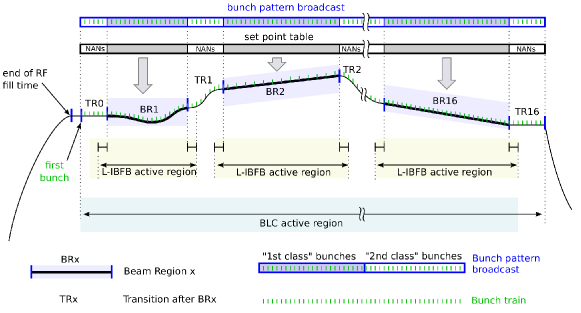
During the summer 2022 shutdown, the so-called "beam regions" (BRs) feature has been released at EuXFEL. It represents a change with respect to the previous multi flat tops scheme [Ayvazyan2008AlternatingFLASH]. The maximum number of flat tops was limited to 3, while now there can be up to 16 beam regions. The beam regions can now have arbitrary shape and are not just limited to a constant amplitude. The beam regions are separated by transition regions (TRs). A schematic view of the concept is shown in Fig. 4. The beam is present over the entire RF flat top but only the bunches accelerated during the BR will be used to lase ("first class" bunches). For this reason, the longitudinal intra bunch train feedback (L-IBFB) stabilizing the bunch arrival time and compression is active during the BRs but switched off during the TRs. The beam loading compensation (BLC) is active throughout. The shape of the BRs is provided by a high-level server, while the set point transitions between BRs are calculated by the LLRF controller server.
When the beam regions are enabled, the RF stations run in the so-called "table mode", while, when disabled, in the "scalar mode", which corresponds to just one flat top. The set point tables are generated by the llrfCtrl server. The llrfCtrl server rejects beam region requests that correspond to exceeding the vector limit of . This is considered to be the maximum deviation, in the complex plane, that is sustainable by the klystron bandwidth. It is possible to easily switch between the table mode and scalar mode by means of the main LLRF panel. The number of beam regions is determined by the Bunch Pattern Builder server [Frohlich2019Multi-beamlineXFEL]. The RF station is recovered in scalar mode after an RF trip. At the moment, at the EuXFEL, the stations from A1 to A5 (i.e. Injector 1, Linac 1 and Linac 2) are running in table mode with up to two beam regions with simple flat top tables. Stations from A6 to A25 (i.e. Linac 3) are operated in scalar mode. Results of flexible operating modes at the EuXFEL, also using the beam regions, are reported in [Guetg2022FlexibleEuXFEL].
4 MARWIN XTL RADIATION SCANS
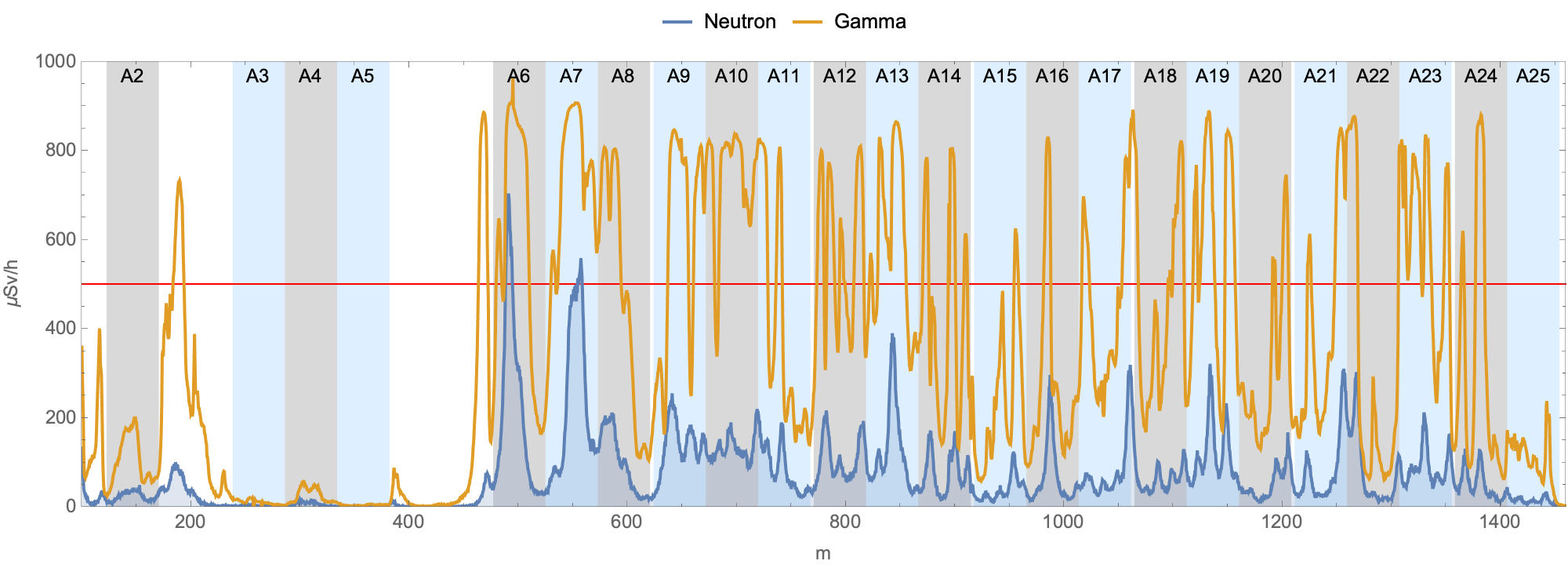
During high-energy runs, weekly radiation scans of the XTL tunnel (i.e. RF stations from A2 to A25) are performed. The scans are run by means of the MARWIN moving robot [Dehne2018Marwin:Environment]. The robot is capable of autonomous motion inside the tunnel and measures instantaneous gamma and neutron radiation levels. If the neutron radiation level of a station repetitively exceeds the administrative limit of , its accelerating gradient is reduced or the emitting cavity identified and detuned. The typical radiation profile of the XTL tunnel during high-energy run is reported in Fig. 5. In the plot, it is possible to observe a high radiation level at the RF station A6. The station has always been affected by cavity field emitters producing dark current. However, in this particular case, the radiation was mainly due to a non optimal setup of the bunch compressor BC2 that lead to beam losses at the chicane. Over the years, several other field emitters have been discovered [Branlard2021FourXFEL].
5 SUMMARY
An overview of the LLRF operations at the European XFEL is given in this paper. The statistics show that the downtime incidence of the LLRF system is maintained at a level <0.3% with respect to the user linac time even though, in 2022, the high-energy user programs have risen to almost 50% of the user time. Due to the large scale of the accelerator, a high degree of automation is provided to assist operators and system experts, including exception detection and handling. New tools and features have been developed to further improve the monitoring and extend the usability of the LLRF system. Among them, there is the LLRF status tool that checks hundreds of DOOCS properties and provides the health status of the whole LLRF system with its subsystems. Another recent new tool is the cavity tuner script. This script, together with its GUI, allows to tune the of all the cavities of an RF stations in a few tens of seconds. Enabling the MTCA hot-plug feature allowed to reduce the time to recover an RF station in case of a faulty board due to SEU. The beam regions feature introduced the possibility to have arbitrary RF shapes in amplitude and phase. Radiation scans are performed weekly during high-energy runs by means of the moving robot MARWIN in order to keep the neutron radiation level of the linac below .
References
- [1] JACoW, http://www.jacow.org
- [2] IEEE Editorial Style Manual, IEEE Periodicals, Piscataway, NJ, USA, Oct. 2014, pp. 34–52.