Non-invasive color imaging through scattering medium under broadband illumination
Abstract
Due to the complex of mixed spectral point spread function within memory effect range, it is unreliable and slow to use speckle correlation technology for non-invasive imaging through scattering medium under broadband illumination. The contrast of the speckles will drastically drop as the light source’s spectrum width increases. Here, we propose a method for producing the optical transfer function with several speckle frames within memory effect range to image under broadband illumination. The method can be applied to image amplitude and color objects under white LED illumination. Compared to other approaches of imaging under broadband illumination, such as deep learning and modified phase retrieval, our method can provide more stable results with faster convergence speed, which can be applied in high speed scattering imaging under natural light illumination.
1 Introduction
How to penetrate random scattering media for quick and reliable non-invasive imaging has become one of the hottest issues in the field of computational imaging, with applications ranging from biological imaging to astronomical imaging[1, 2, 3, 4]. Different methods for non-invasive scattering imaging have been developed recently. Wavefront shaping can be used to image objects behind scattering medium by controlling the spatial light modulator[5, 6, 7]. However, this method usually demands reference objects like a guide star in the plane of interest. Measuring the transmission matrix of the entire scattering system is also an non-invasive imaging method[8, 9]. The determination of the transmission matrix takes long time and requires high precision. Alternatively, it is relatively efficient to measure the point spread function (PSF) of the scattering system and perform a deconvolution operation[10, 11]. However, the method needs prior information and will lose the important advantage of non-invasion imaging.
A breakthrough in the field of non-invasive imaging is on speckle correlation technology (SCT) within optical memory effect range and phase retrieval algorithms[12]. The speckle correlation method based on memory effect draws conclusions from autocorrelation of PSF of the scattering system. Within memory effect range, the speckle autocorrelation approximates the autocorrelation of the object, as shown in Eq. (1)[12], .
| (1) |
where is the speckle captured by camera, is the PSF of the imaging system and is the object in space domain. denotes the autocorrelation operation, and denotes the convolution operation.
The key to Eq. (1) is , which is a sharp peak function. The autocorrelation of PSF can be ignored in the convolution operation[13, 14]. So strict requirement of PSF limits SCT-based method valid for narrow band illumination. Deep learning is an existing reliable method for imaging through scattering media under broad-spectrum illumination[15, 16]. However the method requires a large amount of sample data for an end-to-end learning. Another method is to modify the phase retrieval algorithm by introducing constraints of the phase of OTF (PhTF)[14]. However the iterative process of the phase retrieval algorithm is unstable and the calculation process can take a long time[17].
Broadband spectrum and multi-spectrum are an essential part in color imaging, in which images from different spectrum are superposed to recover the color or the spectral information of object[10]. The current widely used method is to measure the spectral PSF of several discrete spectrum and apply deconvolution or correlation operations on each of them[10, 11]. By this way, the object can be rebuilt with deconvolution operation as Eq. (2)[18],
| (2) |
where is the speckle captured by camera, is the PhTF of the imaging system, is the wavelength of light source, is the object in space domain, and denotes the Fourier transform and inverse Fourier transform, respectively.
However, manipulating spectral PSF can obtain the orientation and position information additionally. Those approaches are limited by the need for prior information of spectral PSF and can not be applied in non-invasion circumstance. As an alternative, a non-invasive triple correlation-based color image reconstruction method was suggested [19]. It contains orientation information which is missing during the traditional speckle correlation. But triple correlation algorithm requires narrow band illumniation source as SCT and it also takes long time to complete than SCT with phase retrieval process[20].
In this paper, The multi-frame OTF retrieval engine (MORE)[21] is used to achieve non-invasive color imaging under broadband illumination by generating OTF with speckles from different objects. It can not only breaks the limitation of speckle correlation imaging technology, but also have stable and fast iterative convergence due to redundant information of speckles.
2 Principle and methods
MORE, has successfully carried out high-speed dynamic imaging under low signal-to-noise ratio circumstances in our earlier work[21]. When the PSF and the speckle for the system’s object have the relationship , the relationship can be expressed in the frequency domain as follows:
| (3) |
where is the speckle pattern, is the object, and for the PSF of the system.
Rewrite Eq. (3) as
| (4) |
in which is the amplitude of the OTF. It is proved that amplitude of the OTF only acts as a spatial frequency filter on [21, 22]. It indicates that the object can be approximated with the speckle pattern and PhTF, :
| (5) |
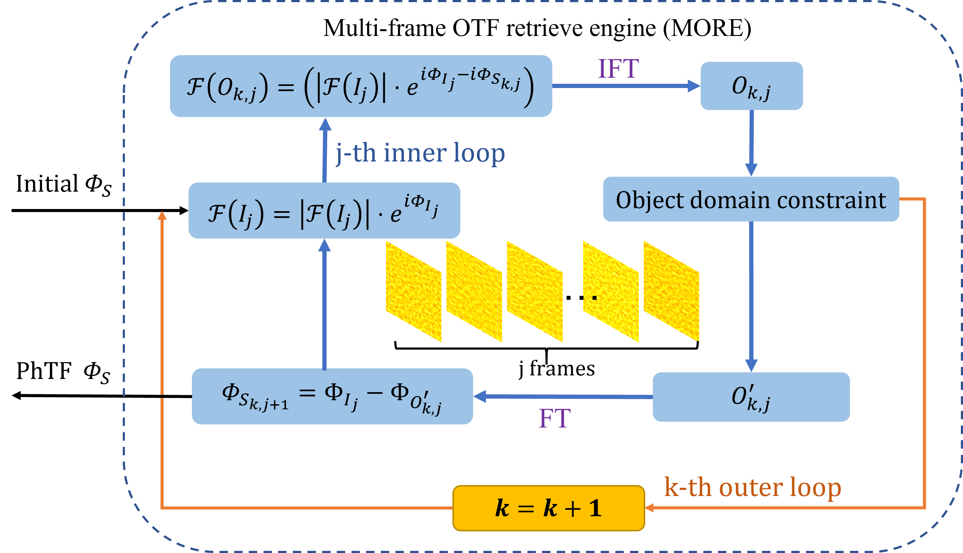
As is shown in Fig. 1, MORE is proposed to generate the PhTF by iteratively computing the Fourier phase among the speckles. In this way, MORE avoids the influence of the PSF autocorrelation introduced in traditional SCT[12], and achieves non-invasive imaging behind the scattering medium under the broadband illumination.
Similar as the Error-Reduction algorithm[23], the iterative process starts in the frequency domain with an initial random guess of PhTF, . In the k-th outer loop and j-th inner iterative loop, the Fourier transform of object, , is calculate with the frequency domain magnitude of speckle and difference of Fourier phase of speckle and PhTF, . After applying an inverse Fourier transform of the object in the frequency domain, we use a real and nonnegative constraint of to update the guessed object, , in object domain. To return to the frequency domain, we performe a Fourier transform on and calculate PhTF with speckle’s phase of Fourier transform, . Then the inner iterative move forward and turn to next frame until all the frames are used. After j-th inner iterative loop is completed, and another time outer loop starts and it goes from the first frame to the last one. When k reaches the number of loops we specify, we can obtain the PhTF of the imaging system, . The objects can be recovered with speckle frames and the PhTF, as Eq. (5) shows.
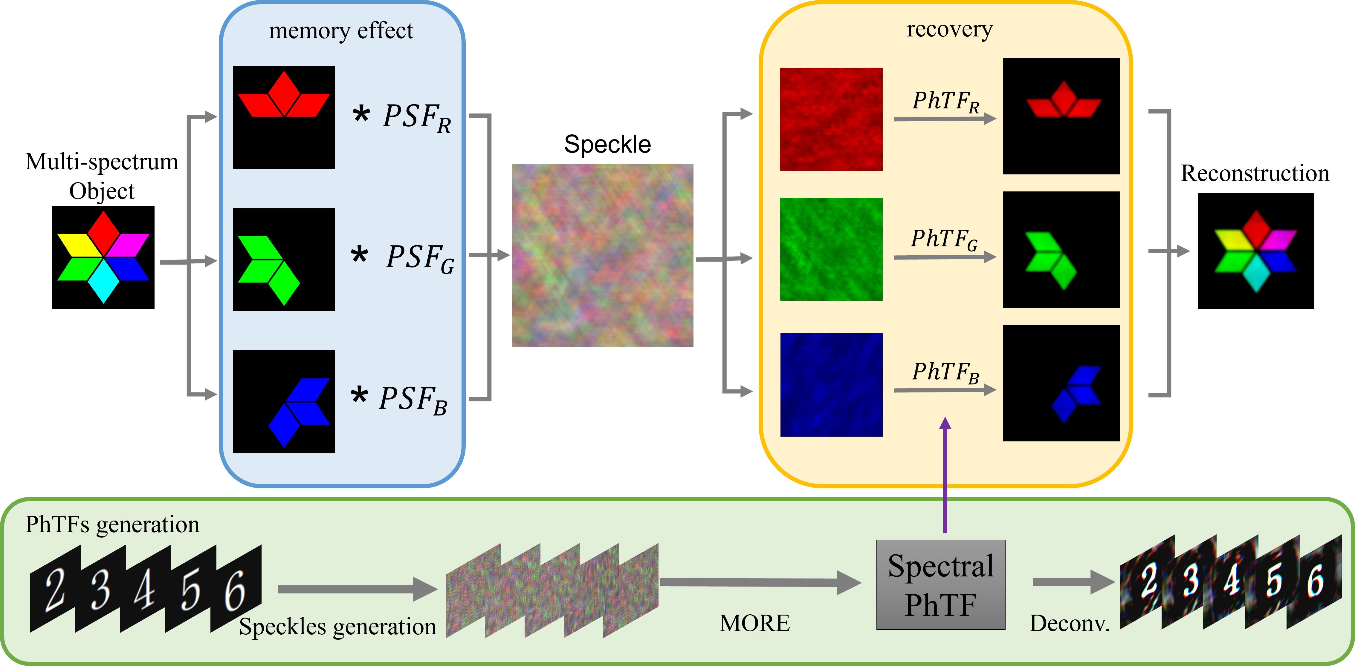
Additionally, by performing OTF retrieval on each of the three broadband spectrum channels separately, MORE can be used for color imaging. Under broadband illumination, speckle pattern is the sum of speckles under narrow band illumination[10, 14]. For the speckle captured by a 3 channel R, G, B color camera, it can be regarded as a sum of the three broadband speckles, which can be described by Eq. (6). By applying MORE in three broadband color channel (R, G, B), we can obtain different PhTF of those channels. Then the object can be retrieved by deonvoluting with PhTF. Equation. (7) shows the deconvolution operation in Fourier domain, where Fourier transform of object is equal to the Fourier transform of speckle divided with PhTF.
| (6) |
| (7) |
Where represents the broadband wavelength ranges of three color channels (R, G, B), is the color speckle with 3 channels captured by camera, is the speckle intensity under wavelength range , is the PSF of imaging system under wavelength range of , is the object under wavelength range of , and denotes the Fourier transform and inverse Fourier transform, respectively.
The recovery pipeline has been explicitly explained using a numerical simulation, as shown in Fig. 2. The object we demonstrate in simulation is a multicolored star. Its three color channels are extracted and combined using three separated PSFs generated randomly. Then, to get three single channel images, we performed a deconvolution operation using only the PhTF, which we have obtained on the R, G, and B images of speckles. By superposing those images, object’s color image was rebuilt.
3 Experimental results
3.1 Amplitude object imaging under LED illumination
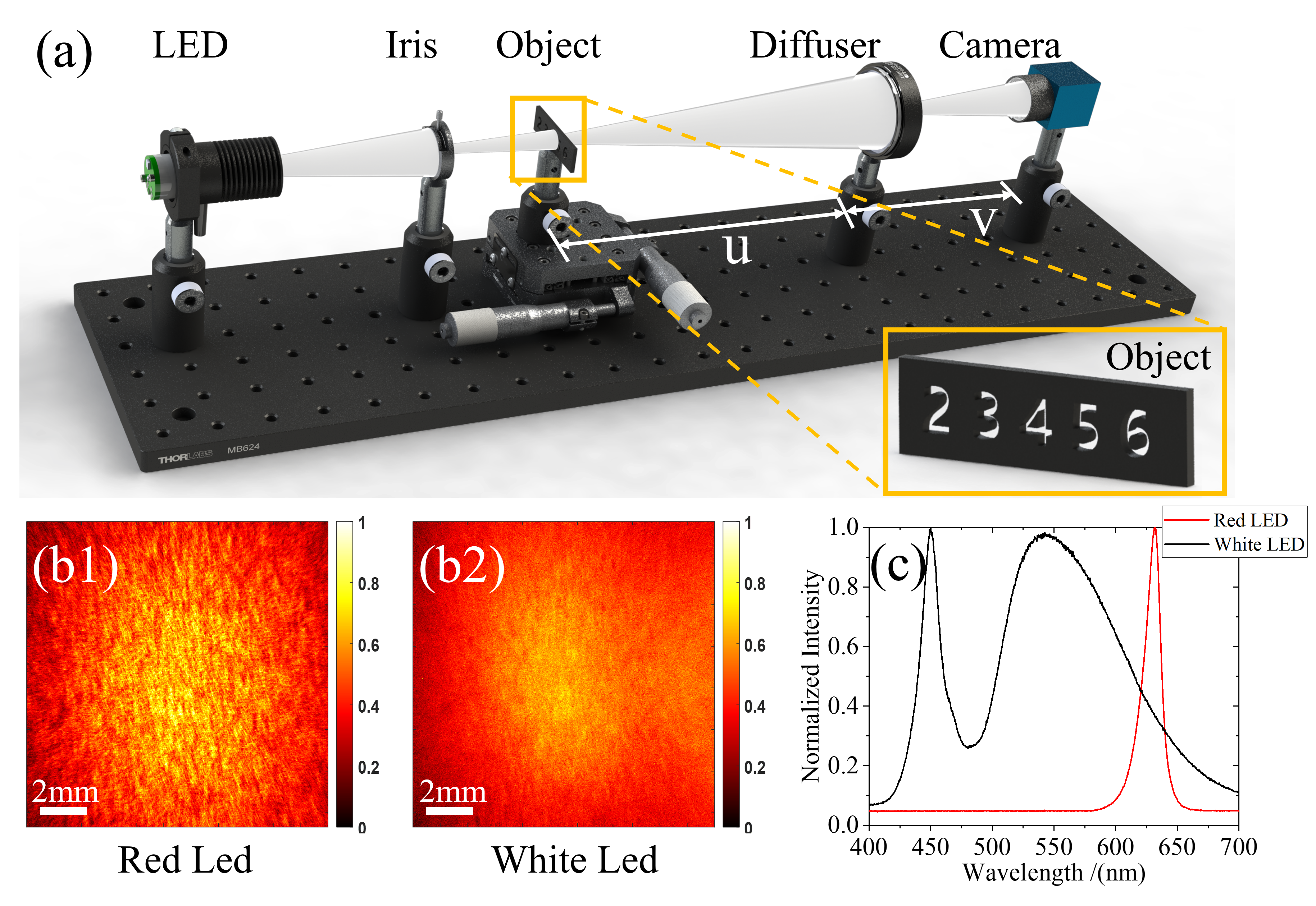
With the setup shown in Fig. 3, we demonstrate non-invasive imaging through a scattering medium under white-light illumination with multi-frame speckle. A white and a red light LED were selected as the light sources. LED’s full width at half maximum of spectrum are about 200 nm and 15 nm, as shown in Fig. 3(c). Several number objects (2.4-mm wide and 3.6-mm high numbers, Fig. 3(a)) were placed at a distance = 200 mm respectively from the diffuser. A CMOS camera (5496 3672 px with a pixel size of 2.4 2.4 m) was placed = 100 mm respectively from the diffuser. Diffuser is a ground glass of 2-mm thickness and 220 grit. The magnification of scattering imaging system was .
As the light carrying the object information passes through the scattering medium, a specific pattern associated with the object was formed, which is captured by the camera behind the scattering medium. After collecting a series of speckles of objects (different number objects ’2’, ’3’, ’4’, ’5’ and ’6’ replaced in our experiment), the raw camera image, Fig. 3(b), was spatial normalized by dividing the raw camera image by a low-pass filter version of it. And then the speckle patterns are smoothed by a Gaussian kernel filter (size: 20 pixels) with a standard-deviation width of 2 pixels to filter out high frequency noise. Note that the support mat constraint is important to the phase retrieval process. The closer the support mat is to the direct imaging size, the more accurate the recovered image will be[23]. Even the support mat ( pixels) is set to be twice object true size ( pixels), MORE can still provides a reasonable result.
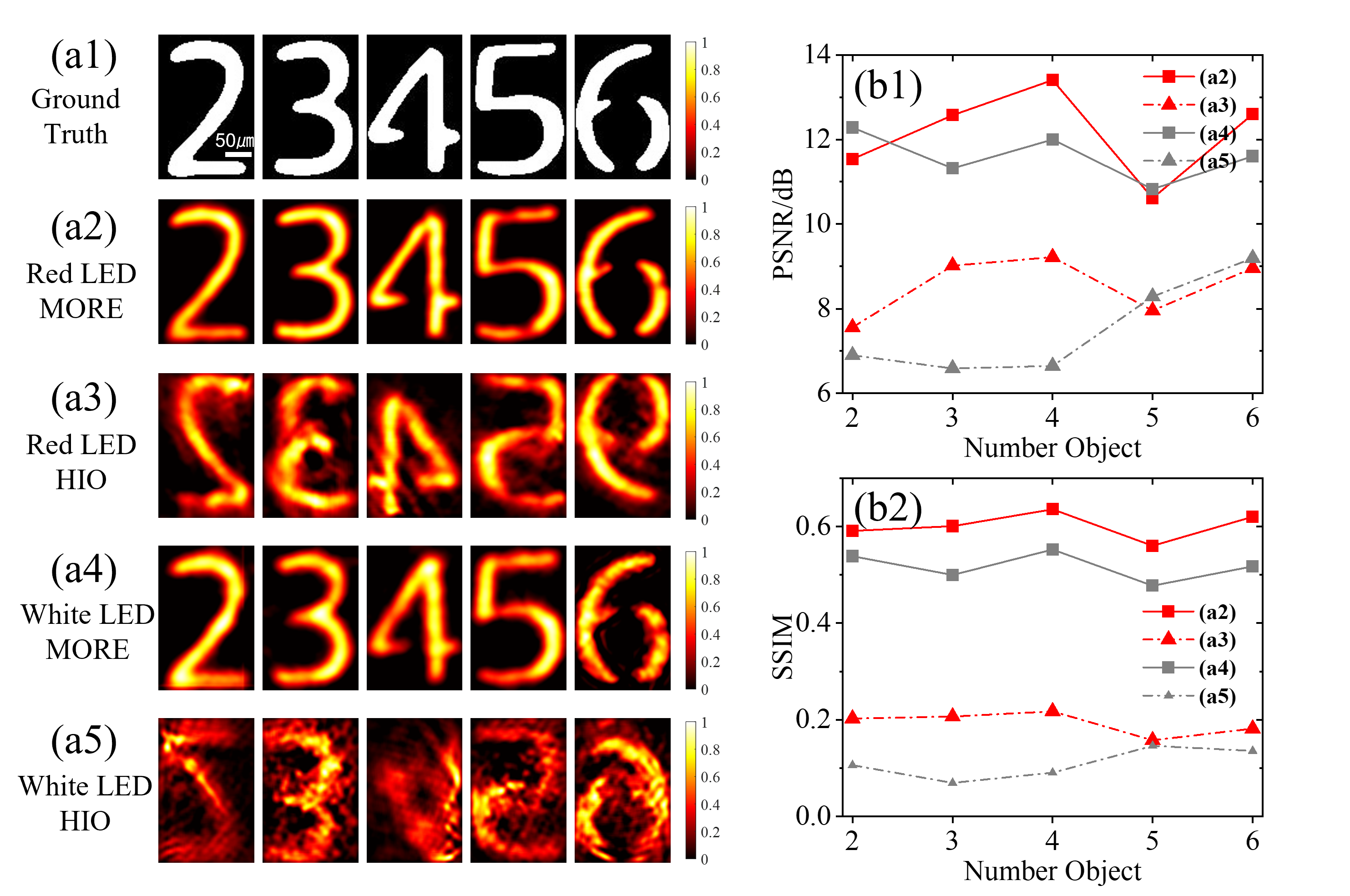
The recovered results of MORE and SCT with phase retrieval algorithm(HIO, hybrid-input-output algorithm) are shown in Fig. 4(a). Under the illumination of 15 nm and 200 nm, results obtained by MORE are better than those got from SCT with phase retrieval algorithm (HIO). The results of HIO shown in Figs. 4(a3) and (a5) are the best recovery images in several trials. There are 50000 iterations for each trail. By comparing MORE’s recovery of the numbers with the objects’ ground truth, the object can be correctly identified. It is worth noting that results from MORE are not selected by us manually and all the recovered images having the correct orientation which is missing in the SCT with phase retrieval process[17]. From Fig. 4(b), both MORE and HIO achieve a better quality under narrower band illumination. As the spectrum becomes wider, the contrast of speckle would be lower, which causes instability of speckle correlation and phase retrieval. However, MORE can still work well under both narrow and broadband illumination. Additionally, we calculate the peak-signal-to-noise ratio (PSNR) and structural similarity index measure (SSIM)[24] of reconstructed image to evaluate the quality of results. And On both PSNR and SSIM, the image of recovered by MORE is better than by HIO among all the five numbers. It shows that our method does work better than SCT and phase retrieval algorithm under broadband illumination.
3.2 Multispectral object imaging
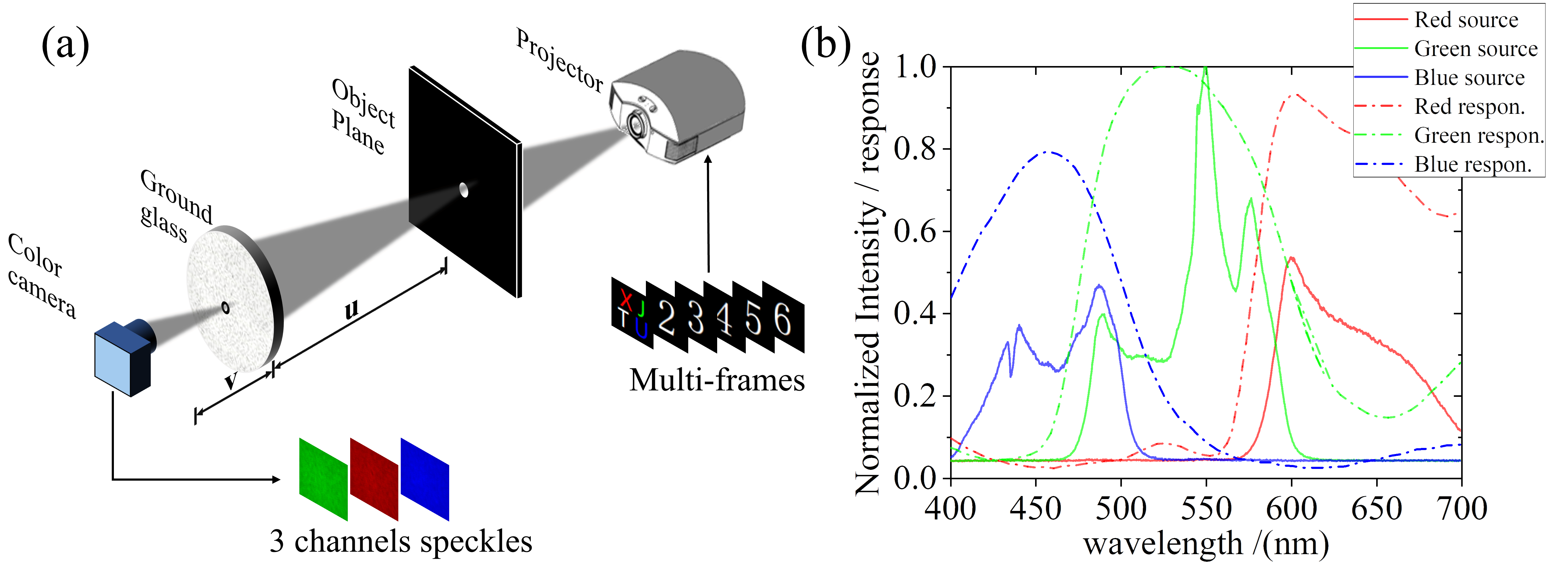
Furthermore, we perform an non-invasive broadband color imaging experiments with MORE. The experiment scheme is shown in Fig. 5(a). The light source and object are replaced by a projector with three broad-spectrum LED light sources. We utilized it to project a series of number objects similar to those in Fig.3. Then we took a serials of pictures of the speckle patterns behind the ground glass with a color camera.
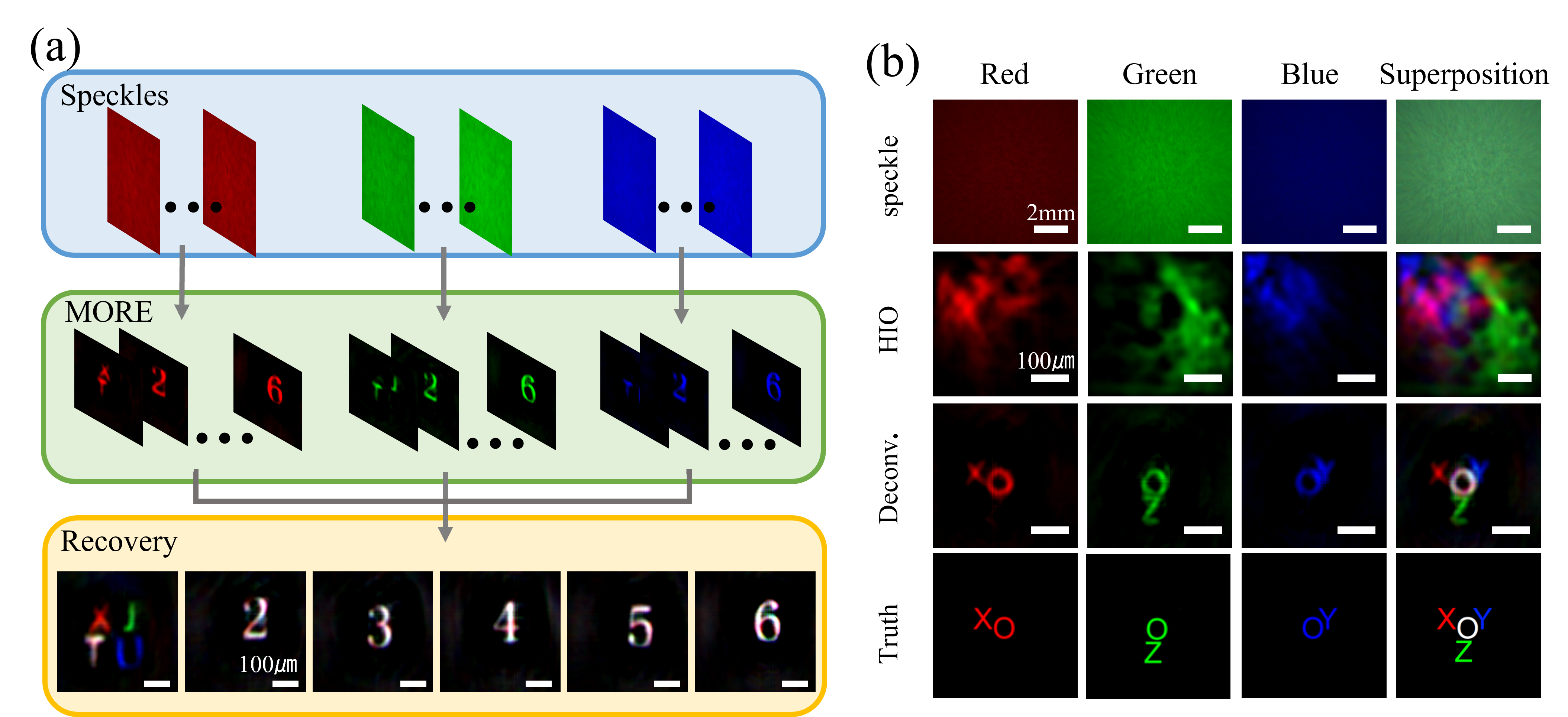
As Fig. 6(a) shows, we extract R, G, and B color channels from the color speckle and obtain PhTF of broadband spectrum by repeating the process mentioned above. Additionally, from the spectrum of projector and camera spectral response curve in Fig. 6(b), blue and red spectrum intensity is comparatively lower than green spectrum intensity when projector brightness is the same. As a result, the gain of the various channels need be adjusted manually to apply the white balance to color camera. We conduct a deconvolution operation with the PhTF produced previously to recover three monochromatic R, G, and B images. Then the color images of white numbers ’2’,’3,’4’,’5’,’6’ and colorful text ’XJTU’ are superimposed by three channels images recovered from three broadband spectrum speckles.
After we obtain the PhTF of the non-invasion scattering imaging system, we conduct another experiment which use another multi-spectral object to evaluate the correctness of PhTF generated by MORE. In Fig. 6(b), three channels of speckle of colorful text ’XYOZ’ are deconvoluted with spectral PhTF obtained by speckles from 6(a). Compared with the truth of object, the images of channels are recovered successfully by deconvoluting with PhTF generated by MORE, while results obtained with phase retrieval algorithm (HIO) fails to recovery the object.
4 Discussion
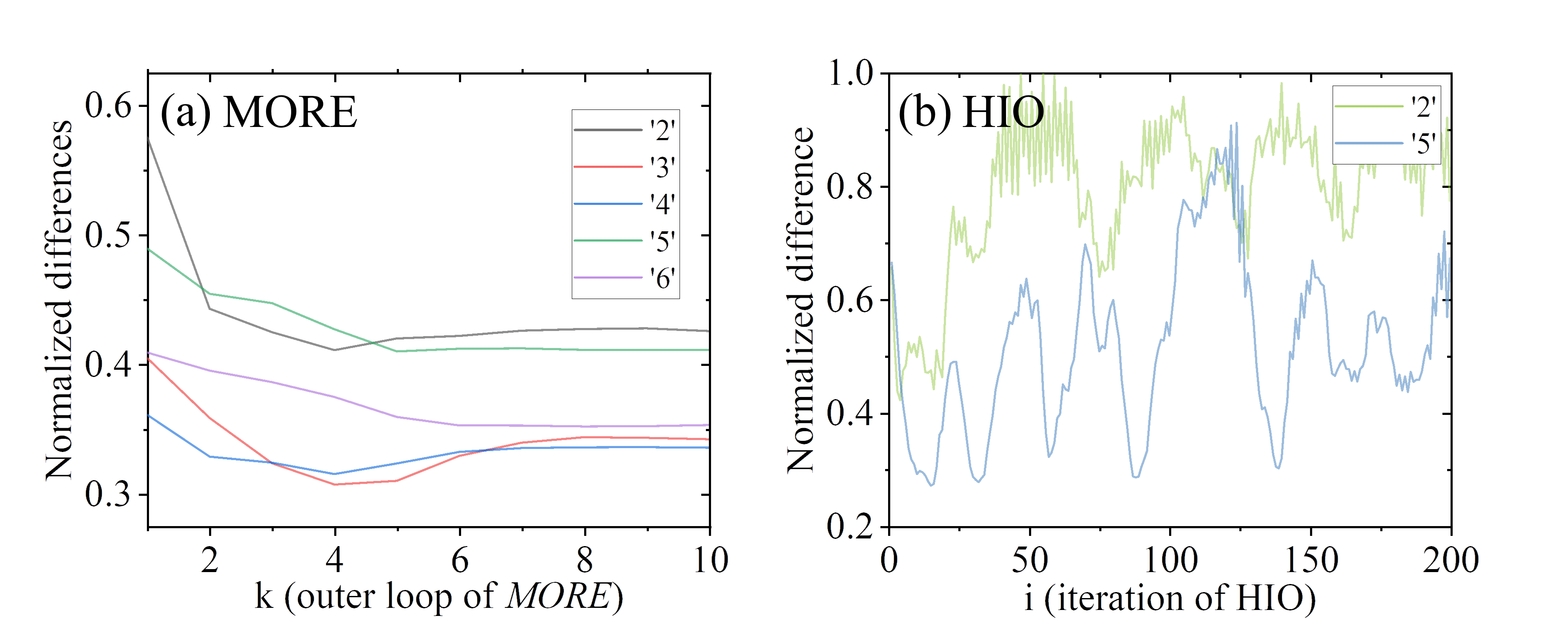
The broadband imaging method we proposed is based on the convolution operation between the object and the PSF within memory effect, as Eq. (4) shows[25]. Compared to the SCT with phase retrieval algorithm, MORE is more like a way to measure PhTF by a serials of frames or dynamic object. Non-invasive color imaging can be achieved by using narrowband light source or adding different narrowband filters before camera[26]. However there is no demand of narrowband source or filters in our method. It has been proved that by modifying phase retrieval algorithm with PhTF, object can be successfully recovered with single frame[14]. However MORE has a faster convergence speed in iteration process and provides more stable and reliable results than modified phase retrieval algorithm. It is because that there is more redundant information of PhTF contained in multi-frame speckles than single-shot frame. As shown in Fig. 7, MORE converges from the first outer iterative loop, and stably reaches its global minimum after the fifth outer loop (equals to 25 times iteration). The SCT with phase retrieval algorithm (HIO) remain unstable even after the 200 times iteration.
A projector has been used as the multi-spectral object and the incoherent light source to simply demonstrate MORE in our work. However, MORE we suggested can still work, when a small colored object within the memory effect is illuminated with white light LED or even natural light. It is important to note that one key benefit of the deconvolution scattering imaging method is the advantage to determine an object’s relative position and orientation. So the spatial position relationship of those items within the memory effect can also be obtained using MORE. Beacuse all the channels of color speckles and spectral PhTF are calculated separately, it is inevitable to superposing color image manually.
5 Conclusion
In conclusion, we prove that our multi-frame OTF retrieve engine (MORE) can be used in non-invasive mono and color imaging under broadband illumination successfully. Compared with existing methods[14, 15, 11, 10], it has no need for prior information of PSF and it achieves a faster and stable convergence and reliable results due to redundant information. MORE overcomes the strict requirements of narrow band illumination and long time consumption on recovery process. It is a effective way to achieve color scattering imaging under broadband illumination.
References
- [1] J. W. Goodman, Speckle Phenomena in Optics: Theory and Applications (SPIE Press, 2020), 2nd ed.
- [2] D. Faccio, A. Velten, and G. Wetzstein, “Non-line-of-sight imaging,” \JournalTitleNature Reviews Physics 2, 318–327 (2020).
- [3] T. Wu, J. Dong, and S. Gigan, “Non-invasive single-shot recovery of a point-spread function of a memory effect based scattering imaging system,” \JournalTitleOpt Lett 45, 5397–5400 (2020). Wu, Tengfei Dong, Jonathan Gigan, Sylvain eng Opt Lett. 2020 Oct 1;45(19):5397-5400. doi: 10.1364/OL.400869.
- [4] G. Barbastathis, A. Ozcan, and G. Situ, “On the use of deep learning for computational imaging,” \JournalTitleOptica 6 (2019).
- [5] O. Katz, E. Small, and Y. Silberberg, “Looking around corners and through thin turbid layers in real time with scattered incoherent light,” \JournalTitleNature Photonics 6, 549–553 (2012).
- [6] I. M. Vellekoop and A. P. Mosk, “Focusing coherent light through opaque strongly scattering media,” \JournalTitleOpt. Lett. 32, 2309–2311 (2007).
- [7] A. P. Mosk, A. Lagendijk, G. Lerosey, and M. Fink, “Controlling waves in space and time for imaging and focusing in complex media,” \JournalTitleNature Photonics 6, 283–292 (2012).
- [8] S. M. Popoff, G. Lerosey, R. Carminati, M. Fink, A. C. Boccara, and S. Gigan, “Measuring the transmission matrix in optics: an approach to the study and control of light propagation in disordered media,” \JournalTitlePhys Rev Lett 104, 100601 (2010).
- [9] D. Andreoli, G. Volpe, S. Popoff, O. Katz, S. Grésillon, and S. Gigan, “Deterministic control of broadband light through a multiply scattering medium via the multispectral transmission matrix,” \JournalTitleScientific Reports 5, 10347 (2015).
- [10] S. K. Sahoo, D. Tang, and C. Dang, “Single-shot multispectral imaging with a monochromatic camera,” \JournalTitleOptica 4 (2017).
- [11] H. Zhuang, H. He, X. Xie, and J. Zhou, “High speed color imaging through scattering media with a large field of view,” \JournalTitleSci Rep 6, 32696 (2016).
- [12] O. Katz, P. Heidmann, M. Fink, and S. Gigan, “Non-invasive single-shot imaging through scattering layers and around corners via speckle correlations,” \JournalTitleNature Photonics 8, 784–790 (2014).
- [13] X. Li, J. A. Greenberg, and M. E. Gehm, “Single-shot multispectral imaging through a thin scatterer,” \JournalTitleOptica 6, 864–871 (2019).
- [14] D. Lu, Q. Xing, M. Liao, G. Situ, X. Peng, and W. He, “Single-shot noninvasive imaging through scattering medium under white-light illumination,” \JournalTitleOpt Lett 47, 1754–1757 (2022).
- [15] S. Zheng, M. Liao, F. Wang, W. He, X. Peng, and G. Situ, “Non-line-of-sight imaging under white-light illumination: a two-step deep learning approach,” \JournalTitleOpt Express 29, 40091–40105 (2021).
- [16] E. Guo, Y. Sun, S. Zhu, D. Zheng, C. Zuo, L. Bai, and J. Han, “Single-shot color object reconstruction through scattering medium based on neural network,” \JournalTitleOptics and Lasers in Engineering 136 (2021).
- [17] J. R. Fienup, “Phase retrieval algorithms: a comparison,” \JournalTitleAppl. Opt. 21, 2758–2769 (1982).
- [18] G. A. Morris, H. Barjat, and T. J. Home, “Reference deconvolution methods,” \JournalTitleProgress in Nuclear Magnetic Resonance Spectroscopy 31, 197–257 (1997).
- [19] L. Zhu, Y. Wu, J. Liu, T. Wu, L. Liu, and X. Shao, “Color imaging through scattering media based on phase retrieval with triple correlation,” \JournalTitleOptics and Lasers in Engineering 124 (2020).
- [20] T. Wu, O. Katz, X. Shao, and S. Gigan, “Single-shot diffraction-limited imaging through scattering layers via bispectrum analysis,” \JournalTitleOpt Lett 41, 5003–5006 (2016).
- [21] Y. Yuan and H. Chen, “Dynamic noninvasive imaging through turbid media under low signalnoise-ratio,” \JournalTitleNew J. Phys 22, 093046 (2020).
- [22] S. Mukherjee, A. Vijayakumar, M. Kumar, and J. Rosen, “3d imaging through scatterers with interferenceless optical system,” \JournalTitleSci Rep 8, 1134 (2018).
- [23] H. H. Bauschke, P. L. Combettes, and D. R. Luke, “Phase retrieval, error reduction algorithm, and fienup variants: a view from convex optimization,” \JournalTitleJ. Opt. Soc. Am. A 19, 1334–1345 (2002).
- [24] A. Horé and D. Ziou, “Image quality metrics: Psnr vs. ssim,” in 2010 20th International Conference on Pattern Recognition, (2010), pp. 2366–2369.
- [25] D. Wang, S. K. Sahoo, X. Zhu, G. Adamo, and C. Dang, “Non-invasive super-resolution imaging through dynamic scattering media,” \JournalTitleNature Communications 12, 3150 (2021).
- [26] L. Zhu, Y. Wu, J. Liu, T. Wu, L. Liu, and X. Shao, “Color imaging through scattering media based on phase retrieval with triple correlation,” \JournalTitleOptics and Lasers in Engineering 124 (2020).