Design of a tabletop interferometer with quantum amplification
Abstract
The sensitivity of laser interferometers is fundamentally limited by the quantum nature of light. Recent theoretical studies have opened a new avenue to enhance their quantum-limited sensitivity by using active parity-time-symmetric and phase-insensitive quantum amplification. These systems can enhance the signal response without introducing excess noise in the ideal case. However, such active systems must be causal, stable, and carefully tuned to be practical and applicable to precision measurements. In this paper, we show that phase-insensitive amplification in laser interferometers can be implemented in a tabletop experiment. The layout consists of two coupled cavities and an active medium comprised of a silicon nitride membrane and an auxiliary pump field. Our design relies on existing membrane and cryogenic technology and can demonstrate three distinct features: (i) the self-stabilized dynamics of the optical system, (ii) quantum enhancement of its sensitivity in the presence of the amplifier, and (iii) optical control of the amplifier gain. These features are needed to enhance the sensitivity of future interferometric gravitational-wave and axion detectors.
I Introduction
Improvements in the performance of gravitational-wave (GW) detectors continue to stretch the known boundaries of precision measurement. Ever since the first discovery of gravitational waves Abbott et al. (2016), there has been a concerted effort to enhance both the sensitivity and bandwidth of these detectors. These allow us to capture a wider range of astrophysical phenomena whose detection is only possible due to their GW emission, such as merger events between black holes Abbott et al. (2016), neutron stars Abbott et al. (2017), or both Abbott et al. (2021a). The current pinnacle of sensitivity is achieved by the Advanced LIGO Aasi et al. (2015) and Advanced Virgo Acernese et al. (2014) detectors and is limited over much of the spectrum by fluctuations brought about by the quantum nature of light Clerk et al. (2010). Improvements beyond previous quantum-induced limitations in interferometric systems have been implemented already, ranging from changes to detector configuration (such as the introduction of signal recycling Gray et al. (1998); Buonanno and Chen (2001)) to implementing direct quantum-noise suppression techniques (such as the squeezed states of light Caves (1981); Aasi et al. (2013); Schnabel (2017); Südbeck et al. (2020); McCuller et al. (2020)). However, there are reasons for further enhancements in the sensitivity and bandwidth of GW detectors. Continuous improvements in detector sensitivity will provide us with deeper and better localization Klimenko et al. (2011); Abbott et al. (2018). Existing performance improvements have led to a faster growing catalog of GW sources Abbott et al. (2019, 2021b, 2021c), which allows us to obtain population statistics Abbott et al. (2021d). Further increases in detector bandwidth can lead to the observation of high-frequency phenomena, such as remnant collapse, aloowing us to probe neutron star physics Miao et al. (2018a); Martynov et al. (2019); Zhang et al. (2021a), and core collapse supernovae Ott (2009); Kotake (2013); Radice et al. (2019).
There is ample motivation for increasing the sensitivity and bandwidth without sacrificing either or, ideally, improving both. The limits on these two properties are imposed by the quantum fluctuations of the light field itself Tsang et al. (2011); Miao et al. (2017), combined with the response of the detector’s optical cavities. It is difficult to achieve simultaneous improvements in both due to the constraints imposed by the Mizuno limit Mizuno (1995), which shows an inverse relationship between the peak sensitivity and bandwidth of the optical system. One of the key insights into this limit is the generation of positive dispersion by the optical cavities present in the system. Several proposals have been made for enhancing the detector performance beyond the standard quantum-imposed constraint using an optomechanical filter cavity Aspelmeyer et al. (2014a); Miao et al. (2015); Li et al. (2019); Bentley et al. (2019); Zhang et al. (2021b); Li et al. (2020, 2021). This system has been variously analysed as a bandwidth-broadening device Miao et al. (2015), a white light cavity Li et al. (2021) and a phase-insensitive filter Dmitriev et al. (2021). Proposals consider the implementation of the filter as an auxiliary cavity attached to existing detectors Miao et al. (2015), or as a conversion of the existing signal-recycling cavity Bentley et al. (2019). A mathematically analogous system has also been proposed that consists of a purely optical implementation Bentley et al. (2021). Many of these proposals consider an unstable system, requiring further active stabilization. In recent studies Li et al. (2020, 2021); Dmitriev et al. (2021), it has been argued that alternate configurations of the filter cavity and the signal read-out scheme can result in a stable system, which still retains sensitivity enhancement beyond the Mizuno limit.
We propose the tabletop layout that can verify the validity of quantum amplification models Bentley et al. (2019, 2021); Li et al. (2021). In a scaled-down system analogous to the analysis in Ref. Li et al. (2021), which was applied to a contemporary GW detector, we make use of a coupled-cavity scheme that augments one cavity with a phase-insensitive amplifier. The amplifier performs a transformation of its input field according to the equation Caves (1982)
| (1) |
where is its output mode, is the filter noise, is the amplifier gain 111We follow the formalism introduced by Caves in Ref. Caves (1982). In Eq. 1, quantities and represent the input and output field and represents the added noise. They can be treated either as the annihilation operators of the corresponding modes of the electromagnetic field in the fully quantum picture or as dimensionless complex amplitudes in the semi-classical approach. We refer to all systems described by this equation as “phase-insensitive amplifiers”, even though the “gain” magnitude can be smaller than or equal to one, i.e. the system can act as an attenuator or a phase shifter., and is the noise coupling coefficient related to according to the equation in order to make the transformation unitary.
The effect relies on the ratio between the optomechanical coupling rate (between the filter cavity and the mechanical resonator) and the optical coupling rate (between the two cavities) being close to unity. Since the latter increases as the main cavity length decreases Martynov et al. (2019), a straightforward down-scaling of the kilometer-size design analyzed in Li et al. (2021) to a tabletop experiment is not possible. Such an experiment, however, is essential for developing deeper understanding of the fundamental physics underlying the parity-time-symmetric quantum filtering before it can be applied to GW detectors. Other technical challenges of the tabletop configuration include accounting for the thermal noise introduced by the mechanical resonator, stabilizing the resonant frequency (locking) of the coupled cavity system, and providing effective mode matching between the small beam waist size for the optomechanical interaction and larger beam size required for the stability of a meter-scale setup.
We show how the challenges listed above can be overcome in a tabletop setup with an appropriate choice of parameters. The proposed interferometer implements an optomechanical interaction of the signal field with a Si3N4 membrane, which can achieve high mechanical quality factors of up to Rossi et al. (2018) at cryogenic temperatures (10 K). The main goals of the proposed experiment are to (i) demonstrate the stability of the optical system with the quantum filter, (ii) measure the propagation of the signal and noise fields in the system (iii) prove that phase-insensitive filtering can improve the sensitivity of quantum-limited interferometric detectors. We outline the theory of quantum amplification in optical interferometers in Section II and find the optomechanical parameters suitable for tabletop demonstration in Section III. We discuss the quantum performance of the setup in Section IV.
II Dynamics of the proposed system
Our design consists of a coupled-cavity interferometer with a resonant mode, , as shown in Fig. 1. The optimised experimental parameters are listed in Table 1. The signal field at frequencies is produced inside the high-finesse main cavity and is further amplified inside the filter cavity. The amplification is achieved by a membrane with a mechanical mode at and an auxiliary pump field at frequency , where is the frequency shift of the mechanical oscillator due to an optical spring in the filter cavity Li et al. (2021).
| Parameter | Symbol | Value |
|---|---|---|
| Main cavity length | 4.1 m | |
| Main cavity input coupler transmissivity | 30 ppm | |
| Main cavity loss | 10 ppm | |
| Filter cavity length | 2 m | |
| Filter cavity bandwidth | 30 kHz | |
| Filter cavity input coupler transmissivity | 0.5 % | |
| Filter cavity loss | 2000 ppm | |
| Membrane eigenmode | 300 kHz | |
| Motional mass | M | 40 ng |
| Membrane thickness | h | 50 nm |
| Membrane transmissivity | 0.8 | |
| Membrane temperature | 10 K | |
| Input pump power | 70 mW | |
| Filter cavity power | 3.4 W | |
| Pump frequency offset | 303 kHz |
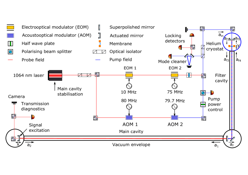
Our layout is similar to a contemporary GW detector with the auxiliary signal recycling cavity tuned to broaden the antenna response at the expense of the gain at DC: the carrier field at the frequency is resonant in the arm cavity but anti-resonant in the signal recycling cavity. Our main cavity and filter cavity can be identified with the arm cavity and signal recycling cavity of the canonical GW detector, respectively. The distinguishing feature of our layout is the silicon nitride (Si3N4) membrane embedded in the filter cavity. Among a vast diversity of optomechanical oscillators Aspelmeyer et al. (2014b), we choose the membrane because it can support relatively large beam sizes ( mm) and can exhibit high mechanical frequencies ( kHz) with a sufficiently high intrinsic tension. These properties make the technology readily applicable to the km-scale Advanced LIGO detectors without changing the g-factors of their signal recycling cavities.
In Li et al. (2021), the mechanical resonator was coupled to the filter cavity as a reflective component. However, the reflectivity of silicon nitride membranes is typically low (). This fact makes their use as a reflective component in the filter cavity impractical due to the high added optical loss. In this section, we show how a pumped membrane dispersively coupled to the coupled-cavity system (i.e. using the membrane-in-the-middle technique Jayich et al. (2008)) leads to the phase-insensitive amplification of the signal field. In the analysis, we consider standard equations for field propagation and interaction at an optical component. The quantum amplification occurs when an optical field interacts with the membrane which is driven by the radiation pressure force from the beat of the pump and signal fields. The optical fields are defined in Fig. 1.
Interference on the input test mass in the main cavity is given by the equations
| (2) |
where and are the round-trip times in the main and filter cavities, and are the field reflectivity and transmissivity of the input mirror of the main cavity, and , where is the relative carrier phase delay across the filter cavity, tuned to to achieve the signal recycling. We keep as a parameter in the following analysis to maintain generality and cover the detuned signal recycling case in future studies.
Microscopic motion of the main cavity causes a small fraction of the static field, , in the main cavity to convert to a time-dependent field near the end mirror according to the equation
| (3) |
where is the displacement of the end mirror and is the speed of light. The field returning to the membrane from the main cavity is given by the equation
| (4) |
The pump field in the filter cavity at frequency converts to frequencies around the carrier field at according to the equations
| (5) |
where is the oscillator motion, and are the field reflectivity and transmissivity of the input mirror of the filter cavity, and and are the field reflectivity and transmissivity of the membrane. The equations above imply that the membrane and the input filter mirror form a low-finesse cavity with an eigenmode at . The oscillator is driven by a thermal force () and back-action force from the beat of the pump with the signal fields () as given by the equation
| (6) |
where is the mass of the oscillator and is its damping rate. The thermal force adds an unwanted noise to the system as discussed in Sec. IV. The radiation force helps achieve the quantum amplification and is given by the equation
| (7) |
The terms refer to pump fields in the filter on both sides of the membrane (the numbering is consistent with the signal fields shown in Fig. 1) and are related to the input pump field according to the equations
| (8) |
where determines the additional phase accumulation of the pump field relative to the carrier field.
Solving the equations above in the frequency domain leads to the input-output relationship between and of the form given by Eq. (1), where the vacuum fields at frequencies around play the role of an additional amplifier noise . The exact expression for is quite complicated, but it can be well approximated as
| (9) |
In the above formula, is related to the signal sideband frequency, , through . The constant quantifies the optomechanical coupling strength between the signal field and the membrane, and it is approximately equal to
| (10) |
Here, is the optical power of the pump field inside the cavity formed by the membrane and the input mirror and dominates over the optical power on the other side of the membrane. Guided by the analysis in this section, we present our choice of experimental parameters in the following section.
III Experimental parameters
The quantum amplification is optimal and stable when the Hamiltonian of the full optomechanical system is parity-time symmetric in the single-mode approximation Li et al. (2020). The condition is fulfilled when the coupling strength, , equals the coupled-cavity resonant frequency, , given by the equation Martynov et al. (2019)
| (11) |
The equation above highlights the complexity of the table-top demonstration of the quantum phase-insensitive amplification: for meter-scale cavity lengths, and , the coupled-cavity resonance is in the tens of kHz range. Therefore, the optomechanical coupling strength, , must be larger for smaller scale experiments than for km-scale ones.
In practice, is chosen to be slightly smaller than to maintain a practical stability margin, as the system becomes unstable for . We choose
| (12) |
which is used in the subsequent sensitivity analysis, as this is the highest value of we confirmed to work in numerical simulations. However, can be optically tuned over the full range of interest (from 0 to above ), which gives us the ability to experimentally explore the margin of stability and the sensitivity enhancement in more detail.
The mechanical eigenmode frequency must satisfy the condition given by the equation
| (13) |
Since the filter cavity bandwidth, , must be larger than the highest signal frequency (), we choose and as shown in Table 1. The relatively low finesse of the filter cavity is similar to that of the Advanced LIGO signal recycling cavity and helps mitigate the negative consequences of the optical losses.
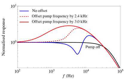
The pump field must be tuned to the resonant frequency of the membrane in the presence of the optical fields. The fields stiffen the mechanical oscillator due to the optical spring effect, which results in a shift of the resonant frequency, given by the equation
| (14) |
and is approximately equal to for our set of parameters. Such a frequency offset is crucial for both improving the sensitivity and maintaining the stability of the system. In Fig. 2, we illustrate its effect on the signal response, which is normalized to unity at low frequencies for clarity. In Fig. 3, we follow Ref. Li et al. (2021) and show the Nyquist plot—a parametric plot of the imaginary and real part of the determinant of with being the identity matrix and the open-loop transfer matrix for the signal field and the idler field. Physically, the frequency offset of the pump field, , is tuned with a pair of acousto-optical modulators (AOMs) as shown in Fig. 1.
Before measuring the quantum sensitivity, the interferometer must to tuned on resonance at . We propose to stabilise the filter and the main cavity relative to the probe field (shown in red in Fig. 1) using the Pound-Drever-Hall scheme. Similar to the Advanced LIGO detectors Aasi et al. (2015), we can stabilise the detector by resonating radio-frequency sidebands in the filter cavity. The resonance is needed to diagonalise the coupled longitudinal degrees of freedom: the filter and main cavities. Our parameter choice implies that the first radio modulation frequency (equal to the free spectral range ) of the filter cavity) should be 75 MHz. For our set of parameters, we get 600 mW of carrier power in the main cavity and 5 uW of carrier power in the filter cavity for the input carrier power of 1 mW. The second modulation frequency is set to 10 MHz to avoid resonances in either cavity. Therefore, we can diagonalise the two degrees of freedom according to the sensing matrix as shown in Table 2.
Stabilisation of the main cavity relative to the pre-stabilised laser can be achieved by demodulating the 10 MHz sideband and actuating on the laser frequency in a high-gain feedback loop. High bandwidth is required to keep stability of the loop when we introduce the pump field. The 75 MHz signal is used to stabilise the filter cavity through actuation on the input filter mirror with a bandwidth of 100 Hz. The pump field leads to the amplification in the filter cavity and increases the optical gain of the detector in the 100 Hz–20 kHz band. Therefore, feedback servos are used to maintain stability across both regimes—with and without the pump field.
| Demodulation frequency | Main cavity | Filter cavity |
|---|---|---|
| 75 MHz | 1 | -1/3 |
| 10 MHz | -1 | 0 |
IV Quantum Sensitivity
In this section, we show that improvements in the quantum-limited sensitivity can be achieved with current technology. In the GW detectors, complex seismic isolation systems are installed to suppress ground vibrations, whereas such advanced systems are not present in our design. In the table-top experiment, we thus tune and the other experimental parameters discussed in Sec. III to achieve the quantum-limited sensitivity improvements at 100 Hz–20 kHz. This is a crucial design choice to avoid coupling of the ground vibrations to the experiment. As a result, the setup is limited by the thermal noise of the membrane and vacuum fields from the interferometer’s open ports: the input port and loss channels in the filter and main cavities.
The effect of the amplification can be classically demonstrated by measuring the transfer function from the main cavity end mirror motion to the readout photodetectors. However, the amplification of the optical gain can be canceled by the noise amplification if the optical and mechanical parameters are not chosen carefully. Our proposal to avoid this excess noise amplification uses a high-quality-factor Si3N4 membrane operated at a cryogenic temperature, which has been recently used in quantum-limited measurements Rossi et al. (2018); Mason et al. (2019).
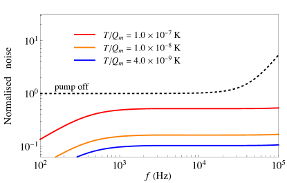
Fig. 4 shows the sensitivity of the same system under consideration for different levels of thermal noise, specified by the ratio . Given this result, it is possible to see real sensitivity improvements for a ratio as large as . A significant improvement in the sensitivity can be achieved for . With a reasonable temperature of 10 K, this implies a constraint of . This parameter regime is achievable with the state-of-the-art Si3N4 membranes.
Optical losses in the main cavity come from scattering and absorption of the laser beam on the optical coating. For our metre-scale setup, optical losses as small as ppm per mirror are routinely achieved by commercially available superpolished mirrors Evans et al. (2013). We follow the formalism discussed in Miao et al. (2018b) and find the noise level imposed by the loss in the main cavity:
| (15) |
where the noise’s power spectral density (PSD) is normalized to the DC level of the noise PSD in the absence of the pump field (i.e. the one provided by the shot noise only), and is the effective power transmissivity of the compound mirror formed by the central mirror, the membrane, and the input mirror.
The filter cavity, similar to the recycling cavities in Advanced LIGO, witnesses larger optical losses due to a larger number of mirrors, the anti-reflective coating of the main cavity input coupler, and mode mismatch between the two cavities. However, the filter cavity loss, , is also less important at low frequencies. If we keep the lowest order to the filter cavity loss, its contribution to the noise level is approximately given by:
| (16) |
where is the bandwidth of the main cavity.
Optical-loss-induced dissipation is analogous to the sensitivity limit from the mechanical dissipation. The thermal noise can be mapped to an equivalent optical loss in the main cavity by using the following equation Miao et al. (2018b):
| (17) |
With the parameters listed in Table 1, corresponds to around 70 ppm loss in the main cavity.
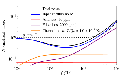
Fig. 4 shows the total noise of our proposed experiment. It includes additional quantum noise from the optical loss in the main cavity and filter cavity. As we can see, given a realistic level of optical loss and ratio of , we could observe a factor of two suppression in the noise level compared to the pump-off case, which is comparable to the quantum noise improvement from squeezed states of light.
The state-of-the-art membranes can achieve even lower values than we need, K, if positioned in a dilution refrigerator Yuan et al. (2015). However, the optical absorption and low thermal conductivity of silicon nitride will increase the membrane temperature Leivo and Pekola (1998); Ftouni et al. (2015) above mK temperatures. We estimate the thermal resistance of a membrane heated by an optical beam at its center as
| (18) |
where is the ratio of the membrane radius to the beam size on the membrane, is the temperature-dependent coefficient of thermal conductivity, and is the membrane’s thickness. The membrane temperature is then given by the equation
| (19) |
where is the power absorbed by the membrane. We compute the power according to the equation
| (20) |
where ppm is the membrane absorption computed using the imaginary part of the film refractive index, Pan et al. (2018), and is the ratio of the power on the membrane to the maximum filter power. Similar to Thompson et al. (2008), we propose to minimise by positioning the membrane at the node of the cavity field.
Solving Eq. 18 and 19 relative to the membrane temperature and approximating W/(mK) around K Ftouni et al. (2015), we get the minimum possible membrane temperature of K with the parameters listed above and in Table. 1. Therefore, we can assume the membrane temperature of K in our estimations of the thermal noise shown in Fig. 4.
V Conclusion
Active parity-time-symmetric and phase-insensitive quantum amplification stands as a promising method of enhancing the quantum-limited sensitivity of interferometric devices. We propose an experiment that has the potential to demonstrate quantum amplification using existing technology on a tabletop scale. This is a crucial step towards embedding the technology in devices such as gravitational-wave and axion detectors. The technology has the potential to increase the reach of the detectors by an order of magnitude Li et al. (2021).
We optimise the experiment to demonstrate quantum amplification with a pair of coupled high-finesse and low-finesse optical cavities. The quantum amplification of the signal field can be achieved with an Si3N4 membrane at K and a properly tuned pump beam. Our design targets the suppression of quantum noises around 100 Hz–20 kHz to avoid noises related to ground and acoustic vibrations.
We explore the stability of such a system in terms of the optomechanical coupling strength, the pump-field frequency, and maintenance of the cavities’ operating point. To this end, we lay out the methods for control of the pump-field frequency using a dual AOM approach, and for the cavity length control using two radio-frequency sidebands in a Pound-Drever-Hall locking scheme. We thus specify a practical solution for the stable control of such a system. Through the setting of the pump-field amplitude (optical control), we are have the ability to alter the amplifier gain in real-time without disrupting operation.
We show that quantum noises from realistic optical losses in the main and filter cavities do not negate the positive effect of the quantum amplification. The choice of the mechanical oscillator (Si3N4 membrane) lets us avoid significant clipping losses in the filter cavity. Moreover, Si3N4 membranes have applications beyond tabletop experiments in km-scale gravitational-wave detectors.
VI Acknowledgements
We thank members of the LIGO QNWG group for useful discussions and Joe Bentley for his valuable feedback. J.S., A.D, and D. M. acknowledge the support of the Institute for Gravitational Wave Astronomy at the University of Birmingham, STFC Quantum Technology for Fundamental Physics scheme (Grant No. ST/T006609/1), and EPSRC New Horizon Scheme (Grant No. EP/V048872/1). H. M. is supported by State Key Laboratory of Low Dimensional Quantum Physics and Frontier Science Center for Quantum Information at Tsinghua. D.M. is supported by the 2021 Philip Leverhulme Prize. C.Z. acknowledge the support of the Australian Research Council (grant No. DP170104424 and CE170100004).
References
- Abbott et al. (2016) B. P. Abbott, R. Abbott, T. D. Abbott, et al. (LIGO Scientific Collaboration and Virgo Collaboration), Phys. Rev. Lett. 116, 061102 (2016).
- Abbott et al. (2017) B. P. Abbott, R. Abbott, T. D. Abbott, et al. (LIGO Scientific Collaboration and Virgo Collaboration), Phys. Rev. Lett. 119, 161101 (2017).
- Abbott et al. (2021a) R. Abbott, T. D. Abbott, S. Abraham, et al. (LIGO Scientific Collaboration and Virgo Collboration and KAGRA Collaboration), The Astrophysical Journal Letters 915, L5 (2021a).
- Aasi et al. (2015) J. Aasi, B. P. Abbott, R. Abbott, et al. (LIGO Scientific Collaboration), Classical and Quantum Gravity 32, 074001 (2015).
- Acernese et al. (2014) F. Acernese, M. Agathos, K. Agatsuma, et al., Classical and Quantum Gravity 32, 024001 (2014).
- Clerk et al. (2010) A. A. Clerk, M. H. Devoret, S. M. Girvin, F. Marquardt, and R. J. Schoelkopf, Rev. Mod. Phys. 82, 1155 (2010).
- Gray et al. (1998) M. B. Gray, A. J. Stevenson, H.-A. Bachor, and D. E. McClelland, Appl. Opt. 37, 5886 (1998).
- Buonanno and Chen (2001) A. Buonanno and Y. Chen, Phys. Rev. D 64, 042006 (2001).
- Caves (1981) C. M. Caves, Phys. Rev. D 23, 1693 (1981).
- Aasi et al. (2013) J. Aasi, J. Abadie, B. P. Abbott, et al. (LIGO Scientific Collaboration), Nature Photonics 7, 613 (2013).
- Schnabel (2017) R. Schnabel, Physics Reports 684, 1 (2017), squeezed states of light and their applications in laser interferometers.
- Südbeck et al. (2020) J. Südbeck, S. Steinlechner, M. Korobko, and R. Schnabel, Nature Photonics 14, 240 (2020).
- McCuller et al. (2020) L. McCuller, C. Whittle, D. Ganapathy, K. Komori, M. Tse, A. Fernandez-Galiana, L. Barsotti, P. Fritschel, M. MacInnis, F. Matichard, K. Mason, N. Mavalvala, R. Mittleman, H. Yu, M. E. Zucker, and M. Evans, Phys. Rev. Lett. 124, 171102 (2020).
- Klimenko et al. (2011) S. Klimenko, G. Vedovato, M. Drago, G. Mazzolo, G. Mitselmakher, C. Pankow, G. Prodi, V. Re, F. Salemi, and I. Yakushin, Phys. Rev. D 83, 102001 (2011).
- Abbott et al. (2018) B. P. Abbott, R. Abbott, T. D. Abbott, et al. (LIGO Scientific Collaboration and Virgo Collaboration and KAGRA Collaboration), Living Reviews in Relativity 21, 3 (2018).
- Abbott et al. (2019) B. P. Abbott, R. Abbott, T. D. Abbott, et al. (LIGO Scientific Collaboration and Virgo Collaboration), Phys. Rev. X 9, 031040 (2019).
- Abbott et al. (2021b) R. Abbott, T. D. Abbott, S. Abraham, et al. (LIGO Scientific Collaboration and Virgo Collaboration), Phys. Rev. X 11, 021053 (2021b).
- Abbott et al. (2021c) R. Abbott, T. D. Abbott, F. Acernese, et al. (LIGO Scientific Collaboration and Virgo Collaboration and KAGRA Collaboration), ArXiv (2021c), arXiv:2111.03606 [gr-qc] .
- Abbott et al. (2021d) R. Abbott, T. D. Abbott, S. Abraham, et al. (LIGO Scientific Collaboration and Virgo Collaboration), The Astrophysical Journal Letters 913, L7 (2021d).
- Miao et al. (2018a) H. Miao, H. Yang, and D. Martynov, Phys. Rev. D 98, 044044 (2018a).
- Martynov et al. (2019) D. Martynov, H. Miao, H. Yang, F. H. Vivanco, E. Thrane, R. Smith, P. Lasky, W. E. East, R. Adhikari, A. Bauswein, A. Brooks, Y. Chen, T. Corbitt, A. Freise, H. Grote, Y. Levin, C. Zhao, and A. Vecchio, Phys. Rev. D 99, 102004 (2019).
- Zhang et al. (2021a) T. Zhang, J. c. v. Smetana, Y. Chen, J. Bentley, D. Martynov, H. Miao, W. E. East, and H. Yang, Phys. Rev. D 103, 044063 (2021a).
- Ott (2009) C. D. Ott, Classical and Quantum Gravity 26, 063001 (2009).
- Kotake (2013) K. Kotake, Comptes Rendus Physique 14, 318 (2013), gravitational waves / Ondes gravitationnelles.
- Radice et al. (2019) D. Radice, V. Morozova, A. Burrows, D. Vartanyan, and H. Nagakura, The Astrophysical Journal 876, L9 (2019).
- Tsang et al. (2011) M. Tsang, H. M. Wiseman, and C. M. Caves, Phys. Rev. Lett. 106, 090401 (2011).
- Miao et al. (2017) H. Miao, R. X. Adhikari, Y. Ma, B. Pang, and Y. Chen, Phys. Rev. Lett. 119, 050801 (2017).
- Mizuno (1995) J. Mizuno, Comparison of optical configurations for laser-interferometric gravitational-wave detectors, Ph.D. thesis, AEI-Hannover, MPI for Gravitational Physics, Max Planck Society (1995).
- Aspelmeyer et al. (2014a) M. Aspelmeyer, T. J. Kippenberg, and F. Marquardt, Rev. Mod. Phys. 86, 1391 (2014a).
- Miao et al. (2015) H. Miao, Y. Ma, C. Zhao, and Y. Chen, Phys. Rev. Lett. 115, 211104 (2015).
- Li et al. (2019) X. Li, M. Korobko, Y. Ma, R. Schnabel, and Y. Chen, Phys. Rev. A 100, 053855 (2019).
- Bentley et al. (2019) J. Bentley, P. Jones, D. Martynov, A. Freise, and H. Miao, Phys. Rev. D 99, 102001 (2019).
- Zhang et al. (2021b) T. Zhang, J. Bentley, and H. Miao, Galaxies 9 (2021b), 10.3390/galaxies9010003.
- Li et al. (2020) X. Li, M. Goryachev, Y. Ma, M. E. Tobar, C. Zhao, R. X. Adhikari, and Y. Chen, “Broadband sensitivity improvement via coherent quantum feedback with pt symmetry,” (2020).
- Li et al. (2021) X. Li, J. Smetana, A. S. Ubhi, J. Bentley, Y. Chen, Y. Ma, H. Miao, and D. Martynov, Phys. Rev. D 103, 122001 (2021).
- Dmitriev et al. (2021) A. Dmitriev, H. Miao, and D. Martynov, ArXiv (2021), arXiv:2110.15354 [quant-ph] .
- Bentley et al. (2021) J. Bentley, H. Nurdin, Y. Chen, and H. Miao, Phys. Rev. A 103, 013707 (2021).
- Caves (1982) C. M. Caves, Physical Review D 26, 1817 (1982).
- Note (1) We follow the formalism introduced by Caves in Ref. Caves (1982). In Eq. 1, quantities and represent the input and output field and represents the added noise. They can be treated either as the annihilation operators of the corresponding modes of the electromagnetic field in the fully quantum picture or as dimensionless complex amplitudes in the semi-classical approach. We refer to all systems described by this equation as “phase-insensitive amplifiers”, even though the “gain” magnitude can be smaller than or equal to one, i.e. the system can act as an attenuator or a phase shifter.
- Rossi et al. (2018) M. Rossi, D. Mason, J. Chen, Y. Tsaturyan, and A. Schliesser, Nature 563, 53 (2018).
- Aspelmeyer et al. (2014b) M. Aspelmeyer, T. J. Kippenberg, and F. Marquardt, Rev. Mod. Phys. 86, 1391 (2014b).
- Jayich et al. (2008) A. Jayich, J. Sankey, B. Zwickl, C. Yang, J. Thompson, S. Girvin, A. Clerk, F. Marquardt, and J. Harris, New Journal of Physics 10, 095008 (2008).
- Mason et al. (2019) D. Mason, J. Chen, M. Rossi, Y. Tsaturyan, and A. Schliesser, Nature Physics 15, 745 (2019).
- Evans et al. (2013) M. Evans, L. Barsotti, P. Kwee, J. Harms, and H. Miao, Phys. Rev. D 88, 022002 (2013).
- Miao et al. (2018b) H. Miao, H. Yang, and D. Martynov, Physical Review D 98, 044044 (2018b).
- Yuan et al. (2015) M. Yuan, M. A. Cohen, and G. A. Steele, Applied Physics Letters 107, 263501 (2015).
- Leivo and Pekola (1998) M. M. Leivo and J. P. Pekola, Applied Physics Letters 72, 1305 (1998), https://doi.org/10.1063/1.120979 .
- Ftouni et al. (2015) H. Ftouni, C. Blanc, D. Tainoff, A. D. Fefferman, M. Defoort, K. J. Lulla, J. Richard, E. Collin, and O. Bourgeois, Phys. Rev. B 92, 125439 (2015).
- Pan et al. (2018) H.-W. Pan, L.-C. Kuo, L.-A. Chang, S. Chao, I. W. Martin, J. Steinlechner, and M. Fletcher, Phys. Rev. D 98, 102001 (2018).
- Thompson et al. (2008) J. D. Thompson, B. M. Zwickl, A. M. Jayich, F. Marquardt, S. M. Girvin, and J. G. E. Harris, Nature 452, 72 (2008).