Active rejection-enhancement of spectrally adaptive liquid crystal geometric phase vortex coronagraphs
Abstract
Geometric phase optical elements made of space-variant anisotropic media customarily find their optimal operating conditions when the half-wave retardance condition is fulfilled, which allows imparting polarization-dependent changes to an incident wavefront. In practice, intrinsic limitations of man-made manufacturing process or the finite spectrum of the light source lead to a deviation from the ideal behavior. This implies the implementation of strategies to compensate for the associated efficiency losses. Here we report on how the intrinsic tunable features of self-engineered liquid crystal topological defects can be used to enhance the rejection capabilities of spectrally adaptive vector vortex coronagraphs. We also discuss the extent of which current models enable to design efficient devices.
Electrical and optical properties of liquid crystals make them attractive material for numerous photonics applications requiring remote changes of the phase or the polarization state of light. This is usually achieved by electrically driven modification of orientational state of the material along the light propagation direction. The transverse spatial orientation state of material brings additional degree of freedom for phase modulation. This is the case for liquid crystal slabs whose orientational state (defined locally by the average molecular orientation to which we assign a unit vector called director) imparts a half-wave birefringent retardation to an incident light field along its propagation direction and space-variant phase profile of a geometric nature in the transverse plane. Their complex amplitude transfer function is given as , where refers to the handedness of the incident circular polarization state and is its effective in-plane optical axis orientation angle. Such geometric phase optical elements were anticipated in the late 1990s bhandari_pr_1997 and experimentally realized a few years after using space-variant solid-state subwavelength gratings bomzon_ol_2002 ; biener_ol_2002 while the advent of their liquid crystal counterparts appeared only a few years later honma_jjap_2005 ; marrucci_prl_2006 .
In the present work we focus on liquid crystal geometric phase optical vortex generators ideally associated with , where is an interger or half-integer and is the polar angle in the plane of the optical element, whose technological maturity and field of use have continued to grow since their first realization in 2006 marrucci_prl_2006 . To date there is a trade-off between, on the one hand, the tunability of the operating wavelength in order to satisfy the half-wave plate condition, which is achieved either by thermal karimi_apl_2009 or electrical piccirillo_apl_2010 means and, on the other hand, the spatial resolution of the structural singularity for the director orientation that can reach sub-micrometer size tabirian_ieee_2015 . Since most applications involve optical beams with cross sections in the millimeter range or larger, they do not suffer from such a compromise. However, this is a priori no longer true when the geometric phase vortex mask is required in the focal plane of an optical system, as is the case for vector optical vortex coronagraphy.
Optical coronagraphy is a high contrast imaging technique originally developed more than 80 years ago to create artificial total eclipses of the Sun lyot_mnras_1939 . The working principle of the original apparatus is to occult the central part of the Airy diffraction pattern in the Fourier plane of a telescope in order to strongly reduce the amount of on-axis stellar light reaching the observer. It was not until nearly sixty years later that the (binary) manipulation of the phase distribution of the Airy spot rather than its occultation was considered roddier_pasp_1997 . Further developments led to the advent of optical vortex coronagraphy where a vortex phase mask with integer values of is centered on the Airy pattern of the on-axis light source to be rejected. Scalar and vector coronagraphy have been proposed simultaneously in Refs. 11 and 12. Their respective labels refer to the physical origin of the phase changes operated by the vortex phase mask: dynamic (scalar case) or geometric (vector case). The superior chromatic performances of the geometric phase option makes vector vortex coronagrahy more attractive. Nowadays, more than one decade after first laboratory mawet_oe_2009 and astronomical mawet_apj_2010 ; serabyn_nature_2010 demonstrations, spectrally static geometric phase vortex masks equip several ground based astronomical observations facilities absil_spie_2016 . Still, it is important to note that spectroscopic imaging of extrasolar planets to learn about their atmospheric composition involves developing broadband vortex masks. This inherently comes with polarization leakage problems and requires demanding technological improvements to mitigate the effects, not only for the vortex mask itself but also for the additional polarization optics involved serabyn_josab_2019 ; doelman_pasp_2020 .
Instead, another approach would be to consider spectrally adaptive geometric phase vortex masks that do not require the use of additional polarization optics and to use them in a narrowband regime while the operating wavelength is scanning the desired spectral bandwidth. However, spectrally adaptive liquid crystal geometric phase vortex coronagraphs reported so far remain hampered by central disorientation region trade-off aleksanyan_ol_2016 ; aleksanyan_prl_2017 ; piccirillo_mclc_2019 . Here we report on how the rejection capabilities of the latter devices can be enhanced.
Noteworthy, there are two distinct kinds of central disorientation in liquid crystal geometric phase vortex masks: (i) the departure from the space-variant pattern (to an unimportant constant) and (ii) the departure from the half-wave birefringent retardance, which could mix in practice. The few previous attempts can be classified as being mainly either on type (i) piccirillo_mclc_2019 or type (ii) aleksanyan_ol_2016 ; aleksanyan_prl_2017 . In the first case, it is difficult to consider post-reprogramming of the fabrication-limited patterned anchoring layers that provide liquid crystal alignment. Nevertheless, the placement of an opaque disk covering the troublesome region is a rough solution applicable regardless of the nature of the vortex mask mawet_apj_2010 . In the second case, which refers to the use of spontaneously formed liquid crystal topological defects under the action of external fields, an additional backup option consists to place the vortex masks between crossed circular polarizers at the expense of throughput losses of at least 50% for unpolarized light observations and additional polarization optics chromatic issues.
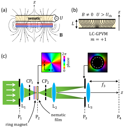
In order to get rid of obstruction and polarization filtering backup strategies for type (ii) vortex masks, one of us suggested a few years ago that adaptive optimization of the size of the disorientation region is an open option when using liquid crystal topological defects called umbilics brasselet_prl_2018 , which is quantitatively explored experimentally in the present work. Also, we discuss the capabilities of available analytical model and full numerical simulation to describe adaptive downsizing of the core of umbilics towards optimal design. Umbilics are nonsingular topological defects associated with unveiled 40 years ago by Rapini rapini_jp_1973 in nematic liquid crystal having negative dielectric anisotropy () and sandwiched between two parallel substrates providing uniform perpendicular orientational boundary conditions for the director ( where is the cell thickness and the unit vector along the axis). These defects spontaneously appear when applying a quasistatic voltage between the two facets of the nematic slab that exceeds the Fréedericksz threshold value where is the bend elastic constant of the nematic and is the vacuum dielectric permittivity rapini_jp_1973 . In our experiments we used a m-thick sample prepared with the dual frequency nematic mixture 1859A (from Military University of Technology, Warsaw, Poland) and umbilics are obtained following the magnetic-electric approach proposed in brasselet_prl_2018 , see Figs. 1(a) and 1(b). The combined action of a static magnetic field from a ring magnet with a quasistatic electric field (square waveform at 200 kHz frequency) enables robust self-engineering of geometric phase vortex masks with above V.
As shown in Fig. 1(c), the mask is placed in the Fourier plane (P2) of a lens (L1, focal length ) illuminated by a collimated expanded laser beam from a supercontinuum source that can be spectrally filtered on-demand using a set of bandpass interferential filters. The input pupil plane P1 is located right before L1 where a metallic circular aperture with radius is placed. A second lens (L2, focal length ) placed at a distance from P2 produces the image of the input pupil in the plane P3 located at a distance from L2, where a metallic circular aperture with radius is placed. Ideally, full rejection of on-axis incident light is achieved when the Airy spot is centered on the vortex phase mask placed in P2 provided that mawet_apj_2005 , as illustrated by the insets of Fig. 1(c). The emulated stellar imaging is made using a third lens (L3, focal length ) by placing a camera in the observation plane P4 located at a distance from L3. To date, optical vortex coronagraphy using umbilics as vortex masks have been made by adjusting the half-wave retardance criterion in the zeroth-order condition for monochromatic laser sources aleksanyan_ol_2016 ; aleksanyan_prl_2017 . This corresponds to birefringent phase retardation set at the asymptotic value , with , sufficiently far from the center of the umbilic defect. The axisymmetry of the umbilics with imposes an optical retardance that vanishes as the distance from the defect center tends to zero, causing the optical vortex mask to deviate from the ideal condition of uniform half-wave retardance. Its detrimental effect is managed by placing the liquid crystal mask between two crossed circular polarizers, which leads to peak-to-peak intensity reduction for the azimuth average coronagraphic images in P4 as reported in Ref. 19; 20.
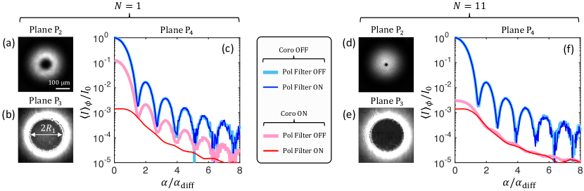
Here our sample provides similar performances for (reached at ) as in our previous works when polarization filtering is activated, see thin curves in Fig. 2(c). In other words, polarization filtering is necessary regardless of the way used (electric, photo-electric or magneto-electric) to create the umbilics-based mask. Once polarization filtering is removed, the coronagraphic performance drastically drops, see thick curves in Fig. 2(c). This visually can be grasped from imperfect ‘ring of fire’ in P3 shown in Fig. 2(b) where one can see that intensity leaks inside the re-imaged area of the input pupil plane (). This is related to the fact that the size of the nonuniform central part of the liquid crystal vortex mask is not negligible compared to that of the Airy spot, see Fig. 2(a). Here we show that increasing the voltage sufficiently far from we can shrink the nonuniform central part of the mask which makes the polarization filtering not needed. The results are shown in Fig. 2(d–f) for , which corresponds to the high-order half-wave condition with .
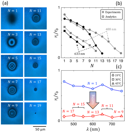
Specifically, the relevant quantity allowing to assess the downsizing of the nonuniform central part of the liquid crystal vortex mask is of light-matter nature. In fact, birefringent phase retardation modulation takes place along the radial coordinate in the vicinity of the center of the umbilic, as illustrated in Fig. 3(a) where the vortex mask is imaged between crossed circular polarizers as is increased by electrical means at fixed temperature. Qualitatively, the vortex mask can be considered as being uniform at a given half-wave retardance order at distance larger than the radius of the last dark ring (or dark area for and ). Quantitatively, this is retrieved from azimuth-average radial intensity profiles by defining the radius of inhomogeneous retardance as the largest value of satisfying . The results are shown in Fig. 3(b) at 488 nm and 633 nm wavelengths, see circle markers. The maximal odd values of that can be reached experimentally depends on the wavelength: for nm and for nm. These values are consistent with the expected asymptotic birefringent phase retardation ( nm) and ( nm) assuming that the director lies in the plane of the mask at all when , where , and taking (at nm and C, manufacturer datasheet). Such a trend can be grasped from Rapini’s analytical model from which the function can be calculated, hence , see Refs. 23; 24 for calculation details. Analytical predictions are shown as square markers in Fig. 3(b), which offers a qualitative rather than a quantitative match with our observations. This can be understood recalling that Rapini’s model assumes monomodal longitudinal profile for the director tilt angle with respect to the axis, namely, , while experimental data support a saturation phenomenon, everywhere, as the magnitude of the electrical torque exerted on the liquid crystal increases.
On-demand optimization ensuring high-order half-wave retardance condition and significant coronagraphic rejection without need of polarization filtering is therefore possible for any operating wavelength. This is illustrated in Fig. 3(c) where the applied electric field and temperature are used as tuning parameters. We reached , where is Airy disc radius, over the wavelength range that covers almost all the visible domain.
Noting that Rapini’s model is not suitable quantitative for the present purpose, we argue that theoretical design of optimized adaptive masks requires more elaborated treatment (Rapini’s model is only valid for ). This can be achieved by relying on Landau-de Gennes free energy minimization full-numerical approach, as reviewed in Ref. 25. In contrast to Rapini’s model, a numerical approach allows to treat exactly the field-matter dielectric coupling without resorting on discarding transverse contributions to the constitutive Maxwell’s equation . Specifically, we jointly solve the full Landau-de Gennes free energy minimization and the generalized Laplace equation for the electric potential in the liquid crystal slab, associated with the boundary conditions and . Dielectric permittivity tensor is directly related to the nematic order parameter tensor as , where is isotropic dielectric permittivity, is molecular dielectric anisotropy, , and summation over double indices is assumed. Also, from the material point of view, the numerical approach allows accounting for possible changes of nematic order in presence of large orientational gradients and handling orientational saturation effects.
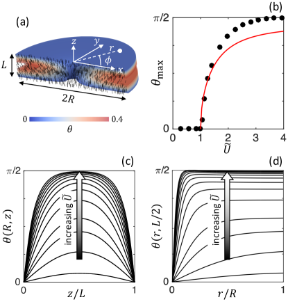
We choose a parallelepipedic simulation box with square cross-section and assume fixed orientational boundary conditions at the edges of the box in all directions, where we imposed , respectively. The free energy minimum is found by solving the Euler-Lagrange equations together with the generalized Laplace’s equation, which eventually gives the director field. A finite-difference relaxation method is used in a cylindrical domain within a computational box with the size of voxels, with a spatial resolution of 10 nm in all directions. We note that computational resources prevent to address the behavior of a sample with the same dimensions as those used in the experiments; however, the demonstrated results to quantitatively describe the adaptive liquid crystal geometric phase vortex mask allows to highlight the need of going beyond Rapini’s model towards designing optimal elements. During the relaxation, the director field on all lattice sites is updated in each time step until the steady state is achieved, usually after a few relaxation steps. This gives reliable results inside a cylindrical domain with radius m for a slab of thickness m, see Fig. 4(a). Indeed, 3 layers of voxels are used on the top and bottom parts of the computational box in order to ensure in the numerical formulation the strong boundary conditions while 125 voxels in the radial direction are found necessary to screen the effects of finite extension of the nematic slab in the plane.
The results are shown in Fig. 4, using single elastic constant pN (neglecting elastic anisotropy), and . In Fig. 4(b) the numerical predictions are compared to Rapini’s model (red curve) that gives accounting for the single elastic constant approximation, see Eq. (13) in Ref. 23. In Fig. 4(c) the simulations clearly exhibit the appearance of high-order odd Fourier components for the longitudinal profile of the director as increases, namely, with . Eventually, Fig. 4(d) displays the radial profile of the director reorientation in the mid-plane of the liquid crystal slab, which we found to moderately depart from the universal profile provided by Rapini’s model as increases.
Summarizing, active enhancement of coronagraphic rejection of adaptive liquid crystal geometric phase vortex masks owing to the combined action of applied electric field and temperature has been demonstrated. The approach consists of reducing the size of the non-ideal central region of the vortex mask, thus getting rid of the polarization filtering otherwise required. The strategy is therefore equally applicable to all wavelengths and do not require the use of additional optical components such as occulting mask mawet_apj_2010 , achromatic polarization optics serabyn_josab_2019 or additional grating doelman_pasp_2020 . As such, present work contributes to the emergence of adaptive optical vortex coronagraphy which is so far restricted to given a spectral operating condition.
N.K. and E.B. thank the support of Conseil Régional de Nouvelle Aquitaine (project HELIXOPTICS). U.M, M.R. and S.Z. acknowledge funding from Slovenian research agency ARRS grants P1-0099, N1-0195 and J1-2462, and EU ERC AdG LOGOS.
References
- (1) R. Bhandari,Polarization of light and topological phases, Phys. Rep. 281, 1–64 (1997).
- (2) Z. Bomzon, G. Biener, V. Kleiner, and E. Hasman,Space-variant pancharatnam-berry phase optical elements with computer-generated subwavelength gratings, Opt. Lett. 27, 1141 (2002).
- (3) G. Biener, A. Niv, V. Kleiner, and E. Hasman,Formation of helical beams by use of pancharatnam-berry phase optical elements, Opt. Lett. 27, 1875 (2002).
- (4) M. Honma and T. Nose,Liquid-crystal fresnel zone plate fabricated by microrubbing, Jpn. J. Appl. Phys. 44, 287 (2005).
- (5) L. Marrucci, C. Manzo, and D. Paparo,Optical spin-to-orbital angular momentum conversion in inhomogeneous anisotropic media, Phys. Rev. Lett. 96, 163905 (2006).
- (6) E. Karimi, B. Piccirillo, E. Nagali, L. Marrucci, and E. Santamato, Efficient generation and sorting of orbital angular momentum eigenmodes of light by thermally tuned q-plates, Appl. Phys. Lett. 94, 231124 (2009).
- (7) B. Piccirillo, V. D’Ambrosio, S. Slussarenko, L. Marrucci, and E. Santamato, Photon spin-to-orbital angular momentum conversion via an electrically tunable q-plate, Appl. Phys. Lett. 97, 241104 (2010).
- (8) N. Tabirian, H. Xianyu, and E. Serabyn,Liquid crystal polymer vector vortex waveplates with sub-micrometer singularity, Proceedings of Aerospace Conference IEEE pp. 1–10 (2015). DOI: 10.1109/AERO.2015.7119168.
- (9) B. Lyot,A study of the solar corona and prominences without eclipses, Mon. Not. R. Astron. Soc. 99, 580–594 (1939).
- (10) F. Roddier and C. Roddier,Stellar coronograph with phase mask, Publ. Astron. Soc. Pac. 109, 815 (1997).
- (11) G. Foo, D. M. Palacios, and G. A. Swartzlander,Optical vortex coronagraph, Opt. Lett. 30, 3308–3310 (2005).
- (12) D. Mawet, P. Riaud, O. Absil, and J. Surdej,Annular groove phase mask coronagraph, Astrophys. J. 633, 1191–1200 (2005).
- (13) D. Mawet, E. Serabyn, K. Liewer, C. Hanot, S. McEldowney, D. Shemo, and N. E. O’Brien,Optical vectorial vortex coronagraphs using liquid crystal polymers: theory, manufacturing and laboratory demonstration, Opt. Express 17, 1902–1918 (2009).
- (14) D. Mawet, E. Serabyn, K. Liewer, K. Burruss, J. Hickey, and D. Shemo, The vector vortex coronagraph: Laboratory results and first light at palomar observatory, Astrophys. J. 709, 53–57 (2010).
- (15) E. Serabyn, D. Mawet, and R. Burruss,An image of an exoplanet separated by two diffraction beamwidths from a star, Nature 464, 1018–1020 (2010).
- (16) O. Absil, D. Mawet, M. Karlsson, B. Carlomagno, V. Christiaens, D. Defrère, C. Delacroix, B. Femenía Castellá, P. Forsberg, J. Girard, C. A. Gómez González, S. Habraken, P. M. Hinz, E. Huby, A. Jolivet, K. Matthews, J. Milli, G. Orban de Xivry, E. Pantin, P. Piron, M. Reggiani, G. J. Ruane, G. Serabyn, J. Surdej, K. R. W. Tristram, E. Vargas Catalán, O. Wertz, and P. Wizinowich,Three years of harvest with the vector vortex coronagraph in the thermal infrared, Proc. SPIE 9908, 99080Q (2016).
- (17) E. Serabyn, C. M. Prada, P. Chen, and D. Mawet,Vector vortex coronagraphy for exoplanet detection with spatially variant diffractive waveplates, J. Opt. Soc. Am. B 36, D13–D19 (2019).
- (18) D. S. Doelman, E. H. Por, G. Ruane, M. J. Escuti, and F. Snik, Minimizing the polarization leakage of geometric-phase coronagraphs with multiple grating pattern combinations, Publ. Astron. Soc. Pac. 132, 045002 (2020).
- (19) A. Aleksanyan and E. Brasselet,Vortex coronagraphy from self-engineered liquid crystal spin-orbit masks, Opt. Lett. 41, 5234–5237 (2016).
- (20) A. Aleksanyan, N. Kravets, and E. Brasselet,Multiple-star system adaptive vortex coronagraphy using a liquid crystal light valve, Phys. Rev. Lett. 118, 203902 (2017).
- (21) B. Piccirillo, E. Piedipalumbo, L. Marrucci, and E. Santamato, Electrically tunable vector vortex coronagraphs based on liquid-crystal geometric phase waveplates, Mol. Cryst. Liq. Cryst. 684, 15–23 (2019).
- (22) E. Brasselet,Tunable high-resolution macroscopic self-engineered geometric phase optical elements, Phys. Rev. Lett. 121, 033901 (2018).
- (23) A. Rapini,Umbilics : Static properties and shear-induced displacements, J. Phys. 34, 629–633 (1973).
- (24) E. Brasselet,Tunable optical vortex arrays from a single nematic topological defect, Phys. Rev. Lett. 108, 087801 (2012).
- (25) M. Ravnik and S. Žumer,Landau–de gennes modelling of nematic liquid crystal colloids, Liq. Cryst. 36, 1201–1214 (2009).