Evidence of linear and cubic Rashba effect in non-magnetic heterostructure
Abstract
The / system serves as a prototype to study the electronic properties that emerge as a result of spin-orbit coupling. In this article, we have used first-principles calculations to systematically study two types of defect-free (0 0 1) interfaces, which are termed as Type-I and Type-II. While the Type-I heterostructure produces a two dimensional electron gas, the Type-II heterostructure hosts an oxygen-rich two dimensional hole gas at the interface. Furthermore, in the presence of intrinsic spin-orbit coupling, we have found evidence of both cubic and linear Rashba interactions in the conduction bands of the Type-I heterostructure. On the contrary, there is spin-splitting of both the valence and the conduction bands in the Type-II interface, which are found to be only linear Rashba type. Interestingly, the Type-II interface also harbours a potential photocurrent transition path, making it an excellent platform to study the circularly polarized photogalvanic effect.
Keywords: non-magnetic heterostructure, spin-orbitronics, Rashba, photogalvanic effect
1 Introduction
Spin based electronics has taken the lead in the fast expanding field of quantum technologies for carrying information by spin instead of charge [1]. These energy-efficient devices necessarily require manipulation of local spins for efficient processing of quantum information. In recent years, manipulation of the spin degree of freedom in solid-state materials via spin-orbit coupling, especially the Rashba spin-orbit coupling, has emerged as one of the most promising approach for developing such next generation energy-efficient electronic devices [2, 3]. Dresselhaus and Rashba were the first to observe that the combined effect of the intrinsic spin-orbit coupling (SOC) and the bulk inversion asymmetry could lead to spin-splitted energy bands in non-centrosymmetric zinc-blende or wurtzite semiconductors [4, 5]. Later, Bychkov and Rashba [6] discovered that spin-splitted energy bands can also appear in two-dimensional materials due to structural inversion asymmetry of the confining potential, which is now commonly referred as Rashba spin-orbit (RSO) interaction. The advantage of controlling the RSO interaction in a material by an external electric field holds the promise to resolve the designing issues of the spintronic devices which typically arises due to the inclusion of local magnetic field [7, 8]. The motivation of designing spin-based electronic devices without the ferromagnetic elements has given rise to the rapidly emerging field of spin-orbitronics [9, 10]. The most effective method of creating spin current inside the non-magnetic materials is by spin-charge interconversion. The electrically induced regulation of the spin dynamics through spin-orbit coupling is the most practical and desirable method of achieving this interconversion [11, 12]. The principle of spin-orbitronics was first explored in semiconductors and metals, though within some years oxide-heterostructures have emerged to be the most promising platform with a plethora of unique characteristics [13]. Complex oxide heterostructures are widely studied for their numerous fascinating properties, such as 2D superconductivity, coexistence of ferromagnetism & superconductivity, colossal magnetoresistance etc. [14, 15, 16, 17], and their promising applications in the manufacturing of next generation all-oxide solid state devices [18, 19]. The interface of a heterostructure made of complex oxide perovskites breaks the structural inversion symmetry and therefore the electron/hole gas confined at the interface experiences a potential gradient perpendicular to the conduction plane [20]. Oxide interfaces offer a flexible platform for creating, controlling, and detecting spin currents or spin textures. based surfaces and interfaces are first observed as the promising candidate for creating two dimensional electron gas (2DEG) with large trasnsport properties and highly confined quantum well [21, 22, 23]. As has strongly correlated 3d-orbital, the effect of intrinsic SOC is expected to be strong in those surfaces and interfaces making the system a suitable platform for generating Rashba spin splitting [24]. The first evidence for RSO interaction in oxide surfaces indeed emerged in the 2DEG generated at the surface along the (0 0 1) direction [25]. Irrespective of various interesting SO-based properties in / heterostructure, one of the main difficulty with this system is the presence of ferromagnetism at the interface, and the RSO interaction is dependent on the magneto-resistance tuning [26].
To overcome this situation, there is an ongoing effort to create oxide heterostructure with non-magnetic interface and stronger SOC, and has emerged as an exciting alternative for its novel electronic as well as spintronic properties due to the presence of the 5d-orbital and high Z-value. [27, 16, 28]. The carrier dependence of spin precision length is shorter in than that in [25]. Due to the polar nature of , the surface with or termination gives rise to naturally induced 2DEG and its counterpart two-dimensional hole gas (2DHG) at the interfaces [29, 30]. , being a polar material, has wide range of properties to be used as a substrate material for its novel surface properties [31, 32]. The in-built electric field at the surface of , provides an ideal system for studying RSO [33] and recently experimental evidences of spin splitting have been found in the surface bands [34, 35]. In comparison to / heterostructure, / has larger charge carrier density at interface with high electron mobility as is also a polar material [36]. Besides, in the bulk state, and are cubic with space group Pmm (No.221). Due to the comparable band gaps and lattice parameters, and are considered as very good candidates for creating heterostructure with an effective charge accumulation at the interfaces. Recently, there have been theoretical and experimental studies of / heterostructures [37, 38]. However, detailed first-principle study on the effect of intrinsic SOC and the possibility of RSO interaction has remained unexplored.
Motivated by this, in this article, we have investigated the electronic and spintronics properties of the / heterostructure for two possible interfaces, which are / (Type-I) and / (Type-II) using density functional theory (DFT) based first-principle calculations. We have found 2DEG in Type-I heterostructure whereas Type-II system exhibit 2DHG in its interface. In the presence of SOC, Type-I system produce both the cubic and linear RSO splitting which has been originated from conduction bands. On the contrary, Type-II heterostructure predominantly produce large k-linear RSO coupling strength which has been produced from both the conduction bands and valence bands. As earlier reported in Ref. [39], the production of circularly polarized photocurrent is possible in slab system where giant RSO interaction is present. Following this, we have found a possible photocurrent transition route for the Type-II system.
In the present report, first we have discussed structural and computational details in section 2. In Section 3 we have discussed on the effective Hamiltonian for the little point group. Following this we have systematically reported the Type-I and Type-II system results in Section 4. The orbital contribution in the absence of SOC has been discussed in subsections 4.1 and 4.3. The explanation of RSO and spin texture for both type systems is covered in sections. 4.2 and 4.4. In section 5, we finally come to a conclusion.
2 Structural and Computational Details
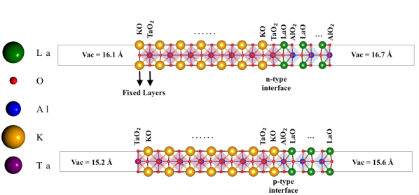
In Fig. 1, we present the asymmetric slab model along (0 0 1) made of and with two types of defect-less interfaces. No strain has been applied in the system. The perovskite oxide material with parent formula can be stacked as and . substrate comprises of alternative and layer, whereas epitaxial layers are made of and sub-layers. To maintain the interface stoichiometry there are two possible kind of interfaces in the heterostructure created by and along (0 0 1) direction, i.e., / and /. Due to the asymmetry present in the heterostructures, both the systems correspond to P4mm (No. 99) space group, which does not have spatial inversion symmetry or the mirror symmetry.
The first-principle density functional calculations are performed by Quantum (QE) package [40]. The exchange-correlation of the electron interactions are taken into account by Perdew-Burke-Ernzerhof (PBE) functional [41]. The projector augmented wave (PAW) basis set has been used to include the interaction between valence electrons and core ions [42]. The on site Coulomb interactions of Ta-5d orbitals are considered by using the standard PBE+U method [43]. The effective value eV is employed for Ta-5d states in this work, as it is well established that such a value is appropriate to describe the strongly-correlated states of KTO [44]. Using the linear response theory implemented in the QE package we have independently verified the value of the Ta-5d states for our heterostructures. The plane-wave basis with a cut-off energy of 75 Ry is used to expand the electronic wavefunctions. Full geometry optimizations are performed using the quick-min Verlet damped dynamics algorithm [45]. Here, -centered k-point grids for sampling [46] the first Brillouin zone are set to for slab models of LAO/KTO heterostructures where m and n are the number of sublayers of and . Scalar relativistic effect has been taken for optimization of the structure and later on fully relativistic effect has been included in selected pseudopotentials to study the SOC effect. It has been tested that there is no significant effect of SOC in the structure optimization. As shown in Fig. 1, in the Type-I heterostructure the bottom two atomic sublayers KO and are kept fixed during structural optimization, while in the case of the Type-II heterostructure no layer has been kept fixed. To minimize the interaction between neighboring slabs, a vacuum layer with a thickness of 30 Å is applied along the z direction (out of plane). All atoms except those in the fixed sublayer/s are fully relaxed until the force acting on each atom is < Ry/Bohr. The convergence criteria of the total energy is set to be < Ry/Bohr. Spin-polarized calculations has been done on the slab system to check the collinear magnetism, which has been found to be zero, and hence all the SOC calculations have been conducted in the slab system by setting the initial magnetism on Ta as 0 . The experimental lattice parameters of bulk and are 3.790 Å and 3.989 Å [47], whereas by using PBE type pseudopotential we have found the theoretical lattice parameters of KTO and LAO to be 4.02 Å and 3.81 Å, which has also been reported earlier [30]. For the heterostructures, we use an average lattice constant of 4.02 Å for both the KTO and LAO regions. The theoretical band gaps of LAO and KTO with PBE pseudopotential are 3.61 eV and 2.84 eV which are comparable with the experimental band gaps 5.6 eV and 3.5 eV respectively [48]. Unlike / heterostructure, there is no critical thickness of epitaxial layers for insulator-to-metal transition in / heterostructure [30].
3 Effective Hamiltonian
The Rashba effect is a momentum-dependent spin-splitting of an energy band resulting from the combined effect of intrinsic spin-orbit interaction and broken inversion symmetry. Both the heterostructures considered in this work have point group symmetry. The little group has three high symmetry points when it is considered for 2D materials, which are (0,0,0), X (0.5,0,0), M(0.5,0.5,0). In these systems, the splitted bands can be described by an effective two band Hamiltonian [49] at point given by,
| (1) |
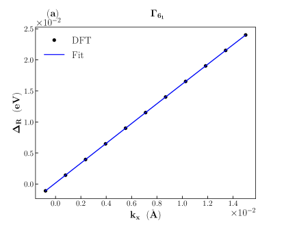
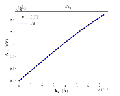
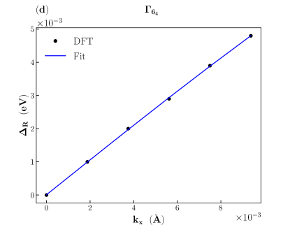
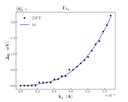
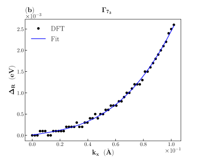
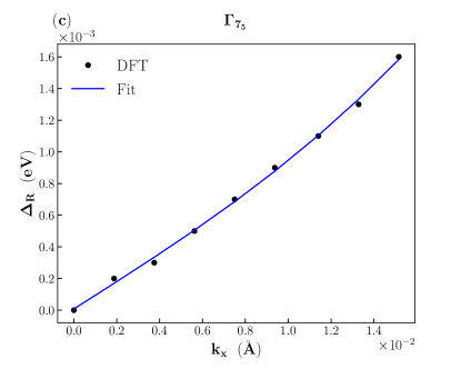
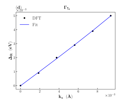
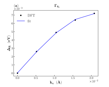
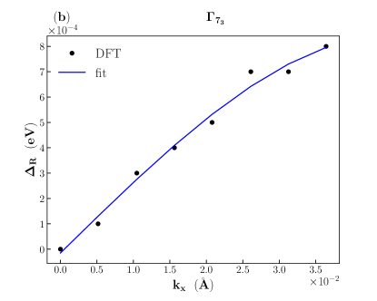
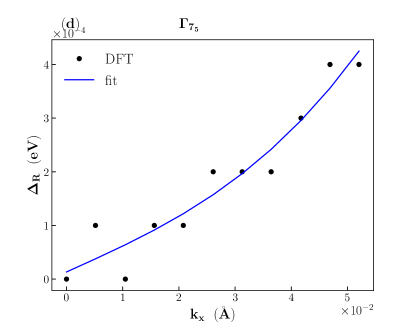
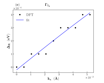
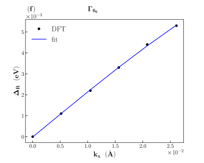
where is the linear RSO interaction term, whereas and are the coefficient of cubic RSO interaction. To estimate the strengths of the linear and cubic RSO interactions in our systems, we consider the high symmetry path. Imposing this condition we solve Eq. 1 to obtain the following two eigenvalue equations given by,
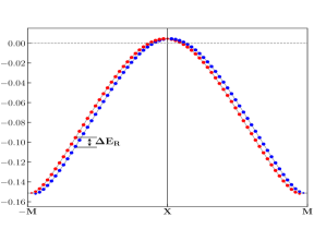
The amount of momentum dependent spin-splitting is given by,
| (2) |
The linear and cubic coupling strengths are obtained by fitting Eq. 3 to the DFT data.
4 Results
In this section we discuss the aforementioned two types of interface made of and . First we present the results of / (type-I) interface which will be followed by / (type-II). The role of SOC and the origin of Rashba interactions are presented along with each of the interface.
4.1 Type-I heterostructure without SOC
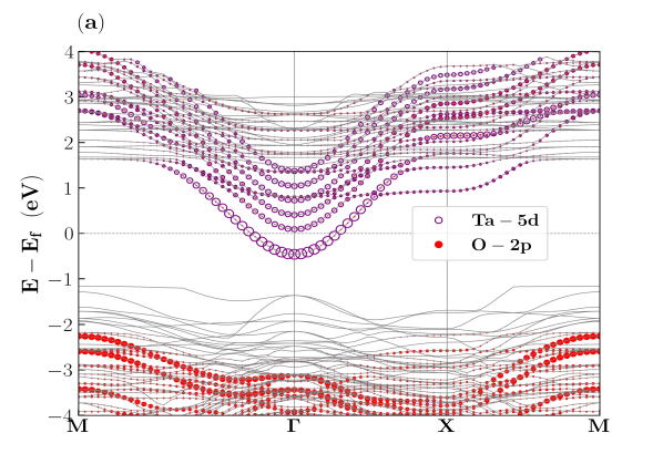
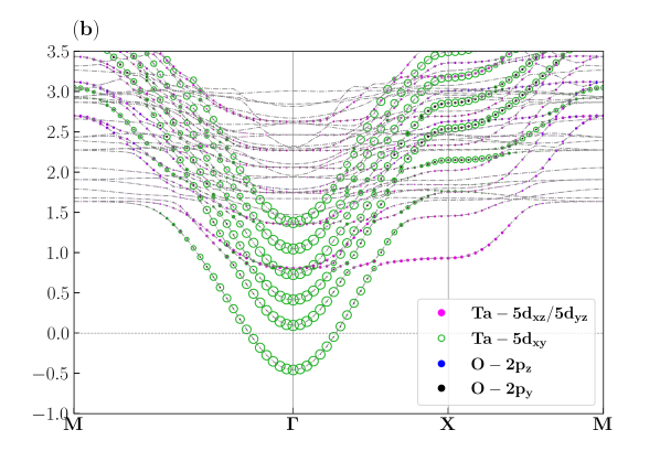
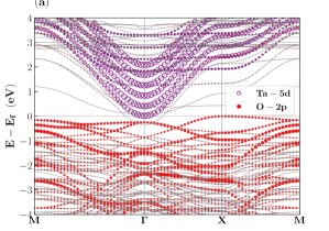
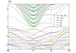
The / interface is made by two polar end of parent materials which helps the accumulation of electron-like carriers at the interface, thereby giving rise to a 2DEG. Fig. 2(a) presents the band structure in the absence of SOC along high symmetry path. The band structure clearly shows that close to the Fermi energy the atomic contributions are mainly due to the Ta-5d orbitals. However, above the Fermi energy at about or more, O-2p orbitals also contribute, albeit tiny, towards the conduction bands. However O-2p orbitals contribute significantly to form the valence bands. The zoomed-in view of the orbital contributions has been presented in Fig. 2(b).
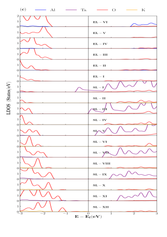
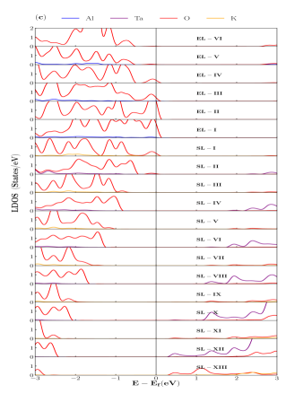
Due to the crystal field splitting (CFS) the degeneracy of the orbitals of Ta-5d are lifted into a singlet and a / doublet. At the interface the band is lower in energy than the or band with a parabolic structure centered around the point. Each band originates from individual sublayer (marked by open green circle in Fig. 2(b)), whereas all the sublayers contribute to form each of the / bands (marked by solid magenta circle in Fig. 2(b)). orbital hybridizes with the / orbitals. The angular momentum of and are same with opposite orientation hence the occupation of and orbitals are equal in weightage. The layer-resolved density of states (LRDOS) without spin-orbit interaction are presented in Fig. 2(c), which reconfirms that the Ta-5d orbitals are predominantly present at the interface that gives rise to the 2DEG.
A visible inter orbital crossing takes place between and / in the path. The inter-orbital crossing between and / bands gives the usual multiorbital (M-O) effect, which has been reported earlier at the interface of / heterostructure [24, 50, 51, 26]. However, in contrast to this earlier reported results, in the case of / heterostructure the M-O effect is not confined within the d-orbitals. Due to the CFS, orbital also takes part along with the d orbitals in this kind of M-O effect. We have found that the orbital hybridizes with the degenerate / orbitals, which has not been reported earlier for -based 2DEG.
4.2 Type-I heterostructure with SOC
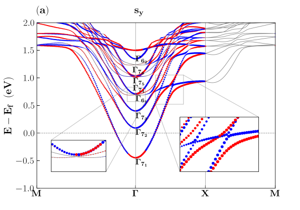
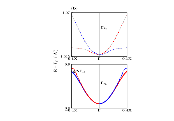
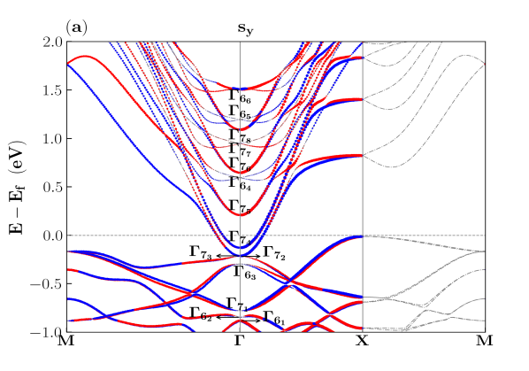
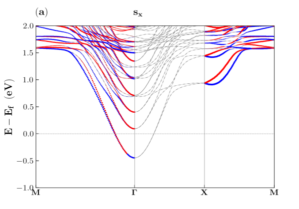
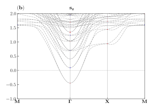
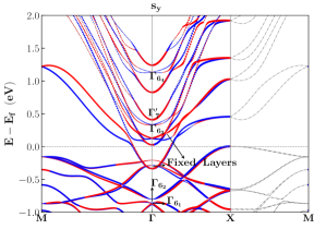
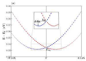
Fig. 3(a) shows the band structure along of the Type-I interface of LAO/KTO heterostructure in the presence of SOC. The spin polarizations are shown (solid red and blue circles) for the component of the spin angular momentum. In Appendix A, the spin polarization of and states are shown in Fig. 8(a) and (b). The spin-splitted Ta-5d orbitals are presented in the left panel. According to the earlier report, the amount of RSO splitting is dependent on the M-O effect present in the system [24, 50, 51, 26]. In Ref. [26], it is found that larger the M-O effect smaller is the RSO splitting. To study the RSO effect, we have confined our study only along the path. In the presence of SOC, all the Ta-5d bands break into the and levels. levels have orbital character of . In Fig. 3(a), we have presented all the levels and two levels. level originates from the subband of subsrate layer (SL-I), and it has no spin-splitting. Systematic study of every level reveals that the spin-splitting gets stronger as we move away from the interface. level has almost no splitting near k=0, whereas for larger k value (around 0.28 Å) it has a splitting at the band crossing region, and it is predominantly cubic like with a RSO coupling strength . has a similar nature like level. The RSO interaction is cubic like with at . In the and levels, for the linear RSO interaction strength is one order magnitude higher than the cubic type RSO with and . It is worthy to mention that in a recent study on semimetal, the maximum spin splitting in Ta has been found to be 269 meV [52]. In this article we have found that a larger splitting in Ta can be achieved by using oxide heterostructure of Ta-based material. level shows a spin flipping across the path (shown in the left inset of Fig. 3(a)). However, there is no spin-splitting of the bands, and it shows similar behavior to the level. The level, which is a complicated combination of / and O-2 subbands, shows a spin-slitting. However, this spin-splitting is not Rashba-like. We have estimated the RSO coupling strengths of each spin-splitted levels by fitting Eq. 3 to our DFT data, and the results are presented in Table 3.
| Orbital | ||
|---|---|---|
| (Band Level) | (eVÅ) | (eVÅ3) |
| – | – | |
| 0.8 | 0.80 | |
| 2.4 | 0.98 | |
| – | – | |
| 0.04 | 39.14 | |
| 0.26 | 113.42 |
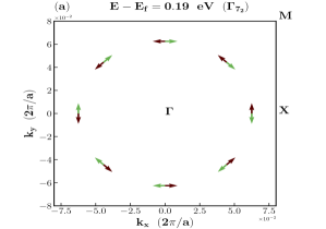
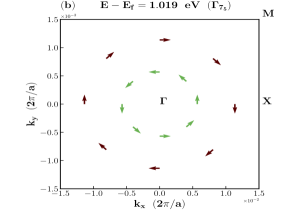
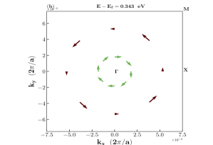
To study the nature of the spin-splitting we have plotted spin texture of the corresponding bands in the plane at a particular energy-cut (light green arrows present the inner band spin orientations and brown arrows present the outer band spin orientations.) Fig. 4(a) shows the spin texture of band at iso-energy +0.19 eV. It is evident that at lower energy, around k=0, there is no spin-splitting of band. However, as pointed out earlier, at about , there is a lateral shift of up and down spin for inner and outer energy bands (figure not shown). Fig. 4(b) shows the spin texture of level at +1.019 eV. This spin texture reconfirms the linear RSO interaction in these bands up-to .
4.3 Type-II heterostructure without SOC
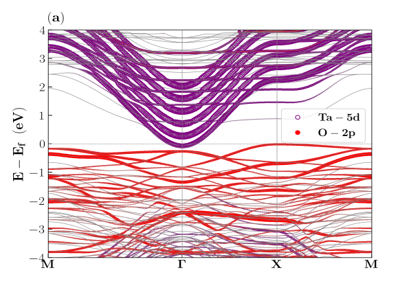
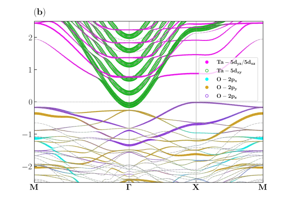
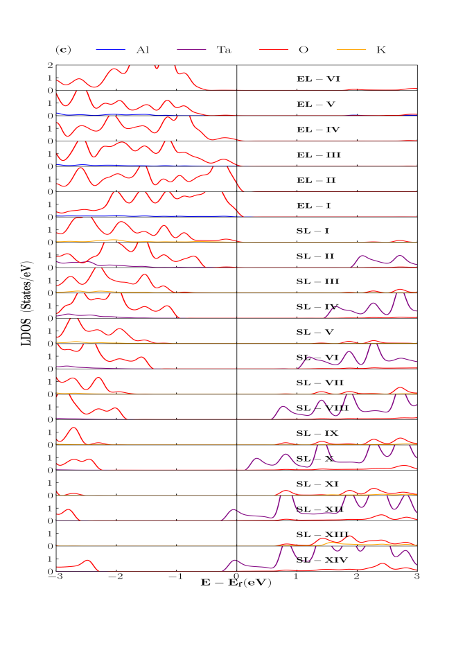
Fig. 5(a) presents the band structure for Type-II system without SOC along high symmetry path. O-2p orbitals (marked with solid red circles) are originated from the polar interface created by and . Band structure shows that the conduction bands are consisted of Ta-5d subbands (marked by open purple circle) which arise from the substrate. The parabolic nature of conduction bands around indicates that there is a creation of quantum well. All the epitaxial and substrate layers are allowed to be relaxed in this heterostructure. Coexistence of electron and hole gas have been observed at and point respectively, in contrast to the earlier reported result [53] for thin film, where similar coexistence is reported at and respectively. Furthermore, we have found that this qualitative feature remains unaltered in the case when the last substrate layer is kept fixed. These results have been presented in the supplemental information. In Fig. 5(b) we have presented the individual orbital contributions of Ta-5d and O-2p orbitals in the system. It is evident that similar to the Type-I heterostructure, the the degeneracy of the subband of Ta-5d orbital is lifted in an identical manner. Moreover, there is a similar inter-orbital crossing of and / bands in this Type-II hetero-interface. In this oxygen-rich interface CFS also plays a crucial role in O-2p orbital splitting. After orbital separation, the valence bands become an admixture of orbitals originated from SL-I and orbitals, originated from EL-I and EL-II. LRDOS for / heterostructure reconfirms the formation of O-rich interface, which presented in Fig. 5(c). Since both the substrate and the epitaxial layers at the interface are made of negatively charged surfaces, the occurrence of hole gas is expected. This can be seen from the valence band maxima (VBM) at X (0.5,0,0) (Fig. 10 shown in Appendix B) which is primarily composed of O- orbitals. The carrier density in this interface is found to be 3.35 1014 cm-2.
4.4 Type-II heterostructure with SOC
In this subsection, we have studied Type-II heterostructure in the presence of SOC, and the corresponding band structure is presented in the Fig. 6. The presence of SOC in Type-II system leads to the formation of the and levels. Distinct and levels are indicated in the band structure by the numerals 1, 2, 3 etc. Unlike Type-I system, here both the and levels show RSO spin splitting.
| Orbital | ||
|---|---|---|
| (Band Level) | (eVÅ) | (eVÅ3) |
| O-() | 0.25 | -182.21 |
| Ta-5 () | 1.41 | -2.26 |
| Ta-5() | 2.88 | -1.17 |
| Ta-5() | 2.35 | 0.59 |
| Ta-5() | 4.30 | 4.60 |
| Ta-5() | 0.11 | -94.60 |
This is an oxygen-rich heterojunction, and in contrast to the Type-I heterostructure, in this system O-2p orbitals exhibit RSO-splitting in the valence band region. band is a hybridized state of O-2. In the valence band region, only band shows Rashba-like spin splitting with and . Suprisingly, we have observed almost a three-fold increase in and more than ten-fold decrease in values when the final substrate layer is kept fixed. These results have been presented in the supplemental information. The spin-splitted band has been presented in Fig. 6(b). , , , are originated from Ta-5 levels of different substrate layers. The RSO spin splitting of these levels are predominantly cubic in nature. In , , , and , , , (which are not shown in Table 4) there a continuous flipping between the two spin channels in the immediate neigbourhood of the point, and hence the observed spin-splitting in these levels are not categorized as RSO spin splitting. level is originated from Ta-5 band and it has predominantly linear RSO coupling strength of . The spin channel in this band survives upto away from . The linear and cubic Rashba coupling strengths for all the spin-splitted levels are presented in the Table 4.

Interestingly, the Type-II system is found to be an ideal system to explore CPGE because it is a member of the point group and possesses a large k-linear RSO splitting with electron spin polarization along . Fig. 7 is a schematic representation of the possible electronic arrangement for producing circularly polarized photocurrent in the system which may provide a likely explanation for the recent experimental observation of CPGE in the LAO/KTO heterostructure [54]. In this system, the required optical transitions for CPGE take place between and levels. For the right-handed polarized light (), the interband transition is possible only for = and similarly for left handed polarized light () the only possible transition is =. and levels are originated from the O-2p and Ta-5d bands of the EL-I and SL-IV, respectively. Surprisingly, this qualitative feature remains unaltered for the same system with fixed substrate layer. However, the transition route of the photocurrent is different for the later case. The results for Type-II system with fixed substrate layer have been presented elaborately in the supplemental material.
5 Conclusion
In conclusion, / and /, both of which are referred to as Type-I and Type-II stoichiometric interfaces, has been individually explored in this work. We have investigated the band dispersion characteristics along the path for both the systems without and with SOC. We have found that, Ta-5 bands can produce the strongest k-linear RSO for Type-I systems with a strength up to 260 meVÅ, while the -RSO coupling can attain a value up-to 113.42 . In this Type-I heterostructure, no RSO splitting is observed in Ta-5 bands. However, Type-II system predominantly produce k-linear RSO in both the Ta-5d and O-2p orbitals. The maximum linear RSO coupling strength for this system is estimated to be 250 meVÅ in O-2p band and 110 meVÅ in Ta-5d band. Furthrmore, we have discovered a possible optical transition path in this Type-II system that may give rise to the circular photogalvanic effect, which is still quite rare in oxide heterostructures.
6 Acknowledgements
The authors would like to thank the computational facility provided by the National Institute of Technology, Rourkela. SB would like to thank Sri Sandipan Dasgupta, Bhaba Atomic Research Centre, VECC, Kolkata, India, for very useful discussions.
References
- Hirohata et al. [2020] A. Hirohata, K. Yamada, Y. Nakatani, I.-L. Prejbeanu, B. Diény, P. Pirro, and B. Hillebrands, Review on spintronics: Principles and device applications, Journal of Magnetism and Magnetic Materials 509, 166711 (2020).
- Bercioux and Lucignano [2015] D. Bercioux and P. Lucignano, Quantum transport in rashba spin–orbit materials: a review, Reports on Progress in Physics 78, 106001 (2015).
- Manipatruni et al. [2019] S. Manipatruni, D. E. Nikonov, C.-C. Lin, T. A. Gosavi, H. Liu, B. Prasad, Y.-L. Huang, E. Bonturim, R. Ramesh, and I. A. Young, Scalable energy-efficient magnetoelectric spin–orbit logic, Nature 565, 35 (2019).
- Dresselhaus [1955] G. Dresselhaus, Spin-orbit coupling effects in zinc blende structures, Physical Review 100, 580 (1955).
- Rashba [1960] E. Rashba, Properties of semiconductors with an extremum loop. i. cyclotron and combinational resonance in a magnetic field perpendicular to the plane of the loop, Sov. Phys.-Solid State 2, 1109 (1960).
- Bychkov and Rashba [1984] Y. A. Bychkov and É. I. Rashba, Properties of a 2d electron gas with lifted spectral degeneracy, JETP lett 39, 78 (1984).
- Awschalom and Samarth [2009] D. Awschalom and N. Samarth, Spintronics without magnetism, Physics 2, 50 (2009).
- Dil [2009] J. H. Dil, Spin and angle resolved photoemission on non-magnetic low-dimensional systems, Journal of Physics: Condensed Matter 21, 403001 (2009).
- Soumyanarayanan et al. [2016] A. Soumyanarayanan, N. Reyren, A. Fert, and C. Panagopoulos, Emergent phenomena induced by spin–orbit coupling at surfaces and interfaces, Nature 539, 509 (2016).
- Trier et al. [2022] F. Trier, P. Noël, J.-V. Kim, J.-P. Attané, L. Vila, and M. Bibes, Oxide spin-orbitronics: spin–charge interconversion and topological spin textures, Nature Reviews Materials 7, 258 (2022).
- Vaz et al. [2019] D. C. Vaz, P. Noël, A. Johansson, B. Göbel, F. Y. Bruno, G. Singh, S. Mckeown-Walker, F. Trier, L. M. Vicente-Arche, A. Sander, et al., Mapping spin–charge conversion to the band structure in a topological oxide two-dimensional electron gas, Nature materials 18, 1187 (2019).
- Manchon et al. [2015] A. Manchon, H. C. Koo, J. Nitta, S. Frolov, and R. Duine, New perspectives for rashba spin–orbit coupling, Nature materials 14, 871 (2015).
- Bibes et al. [2011] M. Bibes, J. E. Villegas, and A. Barthélémy, Ultrathin oxide films and interfaces for electronics and spintronics, Advances in Physics 60, 5 (2011).
- Brinkman et al. [2007] A. Brinkman, M. Huijben, M. Van Zalk, J. Huijben, U. Zeitler, J. Maan, W. G. van der Wiel, G. Rijnders, D. H. Blank, and H. Hilgenkamp, Magnetic effects at the interface between non-magnetic oxides, Nature materials 6, 493 (2007).
- Pentcheva and Pickett [2010] R. Pentcheva and W. E. Pickett, Electronic phenomena at complex oxide interfaces: insights from first principles, Journal of Physics: Condensed Matter 22, 043001 (2010).
- Hwang et al. [2012] H. Y. Hwang, Y. Iwasa, M. Kawasaki, B. Keimer, N. Nagaosa, and Y. Tokura, Emergent phenomena at oxide interfaces, Nature materials 11, 103 (2012).
- Rondinelli and Spaldin [2011] J. M. Rondinelli and N. A. Spaldin, Structure and properties of functional oxide thin films: insights from electronic-structure calculations, Advanced materials 23, 3363 (2011).
- Ohno et al. [1999] Y. Ohno, D. Young, B. a. Beschoten, F. Matsukura, H. Ohno, and D. Awschalom, Electrical spin injection in a ferromagnetic semiconductor heterostructure, Nature 402, 790 (1999).
- He et al. [2021] L. He, J. A. S. Oh, J. J. J. Chua, and H. Zhou, Synthesis and interface modification of oxide solid-state electrolyte-based all-solid-state lithium-ion batteries: Advances and perspectives, Functional Materials Letters 14, 2130002 (2021).
- Winkler [2000] R. Winkler, Rashba spin splitting in two-dimensional electron and hole systems, Phys. Rev. B 62, 4245 (2000).
- Ohtomo and Hwang [2004] A. Ohtomo and H. Hwang, A high-mobility electron gas at the LaAlO3/SrTiO3 heterointerface, Nature 427, 423 (2004).
- Popović et al. [2008] Z. S. Popović, S. Satpathy, and R. M. Martin, Origin of the two-dimensional electron gas carrier density at the LaAlO3 on SrTiO3 interface, Phys. Rev. Lett. 101, 256801 (2008).
- Santander-Syro et al. [2011] A. Santander-Syro, O. Copie, T. Kondo, F. Fortuna, S. Pailhes, R. Weht, X. Qiu, F. Bertran, A. Nicolaou, A. Taleb-Ibrahimi, et al., Two-dimensional electron gas with universal subbands at the surface of SrTiO3, Nature 469, 189 (2011).
- Zhong et al. [2013] Z. Zhong, A. Tóth, and K. Held, Theory of spin-orbit coupling at LaAlO3/SrTiO3 interfaces and SrTiO3 surfaces, Phys. Rev. B 87, 161102 (2013).
- Nakamura et al. [2012] H. Nakamura, T. Koga, and T. Kimura, Experimental evidence of cubic rashba effect in an inversion-symmetric oxide, Physical Review Letters 108, 206601 (2012).
- Kong et al. [2021] W. Kong, T. Yang, J. Zhou, Y. Z. Luo, T. Zhu, J. Chen, L. Shen, Y. Jiang, Y. P. Feng, and M. Yang, Tunable rashba spin-orbit coupling and its interplay with multiorbital effect and magnetic ordering at oxide interfaces, Physical Review B 104, 155152 (2021).
- Caviglia et al. [2010] A. D. Caviglia, M. Gabay, S. Gariglio, N. Reyren, C. Cancellieri, and J.-M. Triscone, Tunable rashba spin-orbit interaction at oxide interfaces, Phys. Rev. Lett. 104, 126803 (2010).
- Gupta et al. [2022] A. Gupta, H. Silotia, A. Kumari, M. Dumen, S. Goyal, R. Tomar, N. Wadehra, P. Ayyub, and S. Chakraverty, KTaO3-the new kid on the spintronics block, Advanced Materials 34, 2106481 (2022).
- Wang et al. [2016] Y. Wang, W. Tang, J. Cheng, M. Behtash, and K. Yang, Creating two-dimensional electron gas in polar/polar perovskite oxide heterostructures: first-principles characterization of LaAlO3/A+B5+O3, ACS applied materials & interfaces 8, 13659 (2016).
- Wang et al. [2020] Y. Wang, Z. Zhang, J. Cheng, Q. Zhang, W. Tang, and K. Yang, Creating a two-dimensional hole gas in a polar/polar LaAlO3/KTaO3 perovskite heterostructure, J. Mater. Chem. C 8, 14230 (2020).
- Li et al. [2003] J. A. Li, E. Akhadov, J. Baker, L. Boatner, D. Bonart, J. Fritsch, S. Safron, U. Schröder, J. Skofronick, and T. Trelenberg, Surface structure and dynamics of KTaO3 (001), Physical Review B 68, 045402 (2003).
- Wang et al. [2022a] Z. Wang, M. Reticcioli, Z. Jakub, I. Sokolović, M. Meier, L. A. Boatner, M. Schmid, G. S. Parkinson, U. Diebold, C. Franchini, et al., Surface chemistry on a polarizable surface: Coupling of co with KTaO3 (001), Science Advances 8, eabq1433 (2022a).
- Kumar and Ganguli [2022] V. Kumar and N. Ganguli, Rashba-like spin-orbit interaction and spin texture at the KTaO3 surface from DFT calculations, Phys. Rev. B 106, 125127 (2022).
- King et al. [2012] P. D. C. King, R. H. He, T. Eknapakul, P. Buaphet, S.-K. Mo, Y. Kaneko, S. Harashima, Y. Hikita, M. S. Bahramy, C. Bell, Z. Hussain, Y. Tokura, Z.-X. Shen, H. Y. Hwang, F. Baumberger, and W. Meevasana, Subband structure of a two-dimensional electron gas formed at the polar surface of the strong spin-orbit perovskite , Phys. Rev. Lett. 108, 117602 (2012).
- Santander-Syro et al. [2012] A. F. Santander-Syro, C. Bareille, F. Fortuna, O. Copie, M. Gabay, F. Bertran, A. Taleb-Ibrahimi, P. Le Fèvre, G. Herranz, N. Reyren, M. Bibes, A. Barthélémy, P. Lecoeur, J. Guevara, and M. J. Rozenberg, Orbital symmetry reconstruction and strong mass renormalization in the two-dimensional electron gas at the surface of KTaO3, Phys. Rev. B 86, 121107 (2012).
- Zhang et al. [2017] H. Zhang, H. Zhang, X. Yan, X. Zhang, Q. Zhang, J. Zhang, F. Han, L. Gu, B. Liu, Y. Chen, et al., Highly mobile two-dimensional electron gases with a strong gating effect at the amorphous LaAlO3/KTaO3 interface, ACS applied materials & interfaces 9, 36456 (2017).
- Zapf et al. [2022] M. Zapf, M. Schmitt, J. Gabel, P. Scheiderer, M. Stübinger, B. Leikert, G. Sangiovanni, L. Dudy, S. Chernov, S. Babenkov, D. Vasilyev, O. Fedchenko, K. Medjanik, Y. Matveyev, A. Gloskowski, C. Schlueter, T.-L. Lee, H.-J. Elmers, G. Schönhense, M. Sing, and R. Claessen, Hard x-ray angle-resolved photoemission from a buried high-mobility electron system, Phys. Rev. B 106, 125137 (2022).
- Varotto et al. [2022] S. Varotto, A. Johansson, B. Göbel, L. M. Vicente-Arche, S. Mallik, J. Bréhin, R. Salazar, F. Bertran, P. L. Fèvre, N. Bergeal, et al., Direct visualization of rashba-split bands and spin/orbital-charge interconversion at KTaO3 interfaces, Nature Communications 13, 1 (2022).
- Wu et al. [2020] N. Wu, X.-J. Zhang, and B.-G. Liu, Strain-enhanced giant rashba spin splitting in ultrathin KTaO3 films for spin-polarized photocurrents, RSC advances 10, 44088 (2020).
- Giannozzi et al. [2009] P. Giannozzi, S. Baroni, N. Bonini, M. Calandra, R. Car, C. Cavazzoni, D. Ceresoli, G. L. Chiarotti, M. Cococcioni, I. Dabo, et al., Quantum espresso: a modular and open-source software project for quantum simulations of materials, Journal of physics: Condensed matter 21, 395502 (2009).
- Perdew et al. [1996] J. P. Perdew, K. Burke, and M. Ernzerhof, Generalized gradient approximation made simple, Phys. Rev. Lett. 77, 3865 (1996).
- Blöchl [1994] P. E. Blöchl, Projector augmented-wave method, Phys. Rev. B 50, 17953 (1994).
- Cococcioni and de Gironcoli [2005] M. Cococcioni and S. de Gironcoli, Linear response approach to the calculation of the effective interaction parameters in the method, Phys. Rev. B 71, 035105 (2005).
- Xu et al. [2021] S. Xu, F. Jia, S. Hu, A. Sundaresan, N. V. Ter-Oganessian, A. P. Pyatakov, J. Cheng, J. Zhang, S. Cao, and W. Ren§, Predicting the structural, electronic and magnetic properties of few atomic-layer polar perovskite, Phys. Chem. Chem. Phys. 23, 5578 (2021).
- Sheppard et al. [2008] D. Sheppard, R. Terrell, and G. Henkelman, Optimization methods for finding minimum energy paths, The Journal of chemical physics 128, 134106 (2008).
- Monkhorst and Pack [1976] H. J. Monkhorst and J. D. Pack, Special points for brillouin-zone integrations, Physical review B 13, 5188 (1976).
- Yang et al. [1990] W.-H. Yang, D.-S. Hou, C.-Z. Li, H. Fan, and H. Y. Zhang, LaAlO3 single crystal substrate for epitaxial superconducting thin films, Solid State Communications 75, 421 (1990).
- Wemple [1965] S. H. Wemple, Some transport properties of oxygen-deficient single-crystal potassium tantalate (KTaO3), Phys. Rev. 137, A1575 (1965).
- Vajna et al. [2012] S. Vajna, E. Simon, A. Szilva, K. Palotas, B. Ujfalussy, and L. Szunyogh, Higher-order contributions to the rashba-bychkov effect with application to the Bi/Ag(111) surface alloy, Phys. Rev. B 85, 075404 (2012).
- Khalsa et al. [2013] G. Khalsa, B. Lee, and A. H. MacDonald, Theory of electron-gas rashba interactions, Phys. Rev. B 88, 041302(R) (2013).
- King et al. [2014] P. King, S. Mckeown Walker, A. Tamai, A. De La Torre, T. Eknapakul, P. Buaphet, S.-K. Mo, W. Meevasana, M. Bahramy, and F. Baumberger, Quasiparticle dynamics and spin–orbital texture of the srtio3 two-dimensional electron gas, Nature communications 5, 3414 (2014).
- Wadge et al. [2022] A. S. Wadge, G. Grabecki, C. Autieri, B. J. Kowalski, P. Iwanowski, G. Cuono, M. Islam, C. M. Canali, K. Dybko, A. Hruban, et al., Electronic properties of taas2 topological semimetal investigated by transport and arpes, Journal of Physics: Condensed Matter 34, 125601 (2022).
- Zhang and Liu [2018] X.-J. Zhang and B.-G. Liu, Strain-driven carrier-type switching of surface two-dimensional electron and hole gases in a KTaO3 thin film, Phys. Chem. Chem. Phys. 20, 24257 (2018).
- Wang et al. [2022b] S. Wang, H. Zhang, J. Zhang, S. Li, D. Luo, J. Wang, K. Jin, and J. Sun, Circular photogalvanic effect in oxide two-dimensional electron gases, Phys. Rev. Lett. 128, 187401 (2022b).
Appendix A Spin polarized band-structures of Type-I
Appendix B Spin polarized band-structures of Type-II
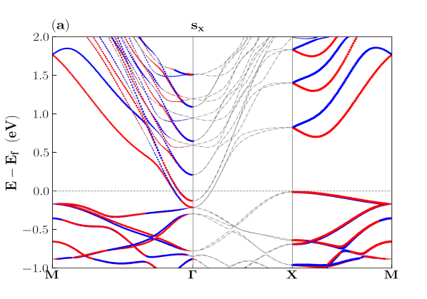
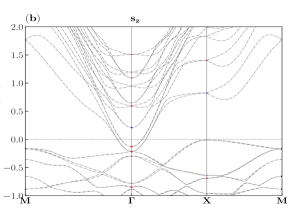
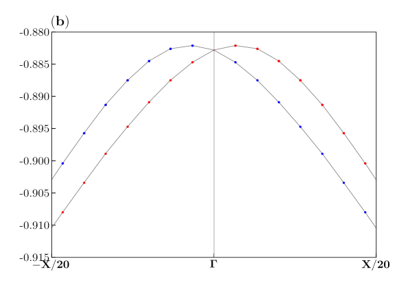
Fig. 9(a) Fig. 9(b) show the Type-II system’s band structure with spin polarization in the x and z directions. The band dispersion exhibits no spin polarization in the direction of z. Spin polarization exists along , however we have not thoroughly examined this system.
At the HS point X (0.5,0,0), the valence band maxima has been seen. The RSO splitting along the M-X-M HS path is cubic-like. This paper does not contain a full discussion of this observation since we have restricted our analysis to the path.
Appendix C Fitting equation obtained from Hamiltonian
| (3) |
C.1 Fitting for RSO parameter in Type-I heterostructure
C.2 Fitting for RSO parameter in Type-II heterostructure without any fixed substrate layer

| Orbital | ||
|---|---|---|
| (Band Level) | (eVÅ) | (eVÅ3) |
| O-() | 0.25 | -182.21 |
| Ta-5 () | 1.41 | -2.26 |
| Ta-5() | 2.88 | -1.17 |
| Ta-5() | 2.35 | 0.59 |
| Ta-5() | 4.30 | 4.60 |
| Ta-5() | 0.11 | -94.60 |
Appendix D Type-II heterostructure with fixed layer
In this section, we have presented the Type-II heterostructure by keeping the last substrate layer at its fixed position. First we have presented the results without the effect of SOC and it is followed by the results including the effect of SOC. Fig. 13(a) presents the band structure for Type-II system without SOC along high symmetry path. O-2p orbitals (marked with solid red circles) are originated from the polar interface created by and . Band structure shows that the conduction bands are consisted of Ta-5d subbands (marked by open purple circle) which arise from substrate. The parabolic nature of conduction bands around indicates that there is a creation of quantum well, although the conduction band minima does not cross the Fermi level. The grey bands without orbital contributions are shown for the fixed layers of the system which do not have any physical significance. In Fig. 13(b) we have presented the individual orbital contributions of Ta-5d and O-2p orbitals in the system. It is evident that similar to the Type-I heterostructure, the the degeneracy of the subband of Ta-5d orbital is lifted in an identical manner. Moreover, there is a similar inter-orbital crossing of and / bands in this Type-II hetero-interface. In this oxygen-rich interface CFS also plays a crucial role in O-2p orbital splitting. After orbital separation, the valence bands become an admixture of orbitals and orbitals, originated from different epitaxial and substrate sub-layers. LRDOS for / heterostructure reconfirms the formation of O-rich interface, which presented in Fig. 13(c). Since both the substrate and the epitaxial layers at the interface are made of negatively charged surfaces, the occurrence of hole gas is expected. Similar to the type-I system, the last layer of this heterostructure has also been kept fixed, and the density of states (DOS) of the fixed layer has not been shown here. The states of the conduction subbands do not have much contribution at the heterojunction.
In this section, we have studied Type-II heterostructure in the presence of SOC, and the corresponding band structure is presented in the Fig. 14.
The presence of SOC in Type-II system leads to the formation of the and levels.
The conduction bands consist of the Ta-5d orbitals, while the valence band consist of O-2p orbitals only.
Distinct levels are indicated in the band structure by the numerals 1, 2, 3 etc. Unlike Type-I system, here all the
levels show RSO spin splitting, whereas levels has no splitting.
This is an oxygen-rich heterojunction, as was previously mentioned, and O-2p orbitals exhibit RSO-splitting in the valence band region.
The zoomed in view of the band, which is a combination of the / orbitals, is presented in
Fig. 15(a) to demonstrate the k-dependent spin splitting () (k path from -0.14X to 0.14X).
In Fig. 15, we have presented the spin texture corresponding to the band, and the texture
clarly shows a modified linear RSO splitting at isoenergy E=. The inner band maintains a constant
spin projection in the plane, while in the outer band the amplitude of the spin projection periodically changes with momentum.
In order to estimate the RSO coupling strength for Type-II system, the DFT band dispersion data is fitted with Eqn. 3.
In Table 5, the results for all the bands are presented.
For both the and bands, linear RSO coupling strength is very strong with and
respectively.
In the conduction band region, up-to within , and level
shows linear RSO splitting with coupling strength 200 meVÅ and 260 meVÅ respectively.
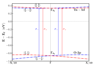
Fig. 16 is a schematic representation of the possible electronic arrangement for producing circularly polarized photocurrent in the LAO/KTO heterostructure. For the right-handed polarized light (), the interband transition is possible only for = and similarly for left handed polarized light () the only possible transition is =. In the Type-II system, we have shown schematically the transition takes place between and levels which belong to EL-I and SL-X.
D.1 Fitting for RSO parameter in Type-II heterostructure with fixed substrate layer
| Band level | ||
|---|---|---|
| (eVÅ) | (eVÅ3) | |
| 0.78 | -15.3 | |
| 0.80 | -19.4 | |
| 0.20 | -3.2 | |
| 0.26 | -85.4 |