Composition-tunable magnon-polaron anomalies in spin Seebeck effects
in epitaxial BixY3-xFe5O12 films
Abstract
We have investigated hybridized magnon-phonon excitation (magnon polarons) in spin Seebeck effects (SSEs) in BixY3-xFe5O12 (BixY3-xIG; , , and ) films with Pt contact. We observed sharp peak structures in the magnetic field dependence of the longitudinal SSE (LSSE) voltages, which appear when the phonon dispersions are tangential to the magnon dispersion curve in BixY3-xIG. By increasing the Bi amount , the peak fields in the LSSE shift toward lower values due to the reduction of the sound velocities in BixY3-xIG. We also measured the SSE in a nonlocal configuration and found that magnon-polaron anomalies appear with different signs and intensities. Our result shows composition-tunability of magnon-polaron anomalies and provides a clue to further unravel the physics of magnon-polaron SSEs.
I INTRODUCTION
Bismuth (Bi) substituted yttrium iron garnet (YIG) has been an important material in magnetics and magneto-optics Hansen1983PRB ; Hansen1984ThinSolidFilms . In spite of Bi3+ being a diamagnetic ion, via the spin-orbit interaction, the substitution dramatically increases the Faraday rotation angle of garnets (by a factor of compared to primitive YIG Hansen1983PRB ; Hansen1984ThinSolidFilms ), which led to its versatile magneto-optical application. Another interesting feature of Bi-substituted YIG (Bi:YIG) includes the increased Curie temperature Hansen1983PRB ; Hansen1984ThinSolidFilms and magnetoelastic interaction Kumar2019JPCM . Fabrication of strained Bi:YIG ultrathin films with perpendicular magnetic anisotropy and low Gilbert damping has also been reported, offering a new opportunity for their spintronic applications Soumah2018NatCommun ; Evelt2018PRAppl ; Chumak2022IEEE . Furthermore, because of the atomic mass of Bi () much larger than that of Y (), a decrease of the sound velocities of Bi:YIG () has been reported for both the transverse acoustic (TA) and longitudinal acoustic (LA) modes compared to those of YIG () Zhang1993PRB ; Siu2001PRB , as schematically shown in Fig. 1(a) (see also Table 1) .
Lately, in spintronics, magnon-phonon coupled phenomena have renewed attention, where not only magnon but also phonon dispersion relations play an important role Dreher2012PRB ; Ogawa2015PNAS ; Shen2015PRL ; Guerreiro2015PRB ; Kikkawa2016PRL ; Bozhko2017PRL ; Hashimoto2017NatCommun ; Holanda2018NatPhys ; Hashimoto2018PRB ; Hayashi2018PRL ; Yahiro2020PRB ; An2020PRB ; Godejohann2020PRB ; Hioki2020ComPhys ; Frey2021PRB ; Zhang2021NatCommun ; Schlitz2022PRB . Of particular interest is the region of the crossings of their branches, at which magnons and phonons are allowed to hybridize by the magnetoelastic interaction, giving rise to the magnon-polaron modes having both magnonic and phononic characters Shen2015PRL ; Kikkawa2016PRL ; Flebus2017PRB . In thermal magnon-spin transport, or the spin Seebeck effect (SSE) Uchida2010APL ; Uchida2014JPCM ; Uchida2010ProcIEEE ; Kikkawa2023ARCMP , the magnon-polaron formation manifests as anomalous peak or dip structures at the onset fields , where the phonon dispersions in a magnet tangentially touch the magnon dispersion gapped by the Zeeman interaction ( external magnetic field ) [see Fig. 1(b)] Kikkawa2016PRL ; Flebus2017PRB . A calculation based on Boltzmann transport theory reveals that, when the scattering rate of magnons is larger (smaller) than that of phonons , magnon polarons may have a longer (shorter) relaxation time than pure magnons. The SSE intensity is therefore enhanced (suppressed) at the touching fields, where the effect of magnon-polaron formation is maximal Flebus2017PRB . So far, through longitudinal SSE (LSSE) experiments, magnon-polaron peaks have been detected for several magnetic films, indicating the situation of Kikkawa2016PRL ; Wang2018APL ; Ramos2019NatCommun ; Xing2020PRB ; Li2020PRL_Cr2O3 ; Yang2021PRB , while dips were observed for some specific YIG bulk samples (i.e., ) Kikkawa2023ARCMP ; Shi2021PRL_YIG-bulk .
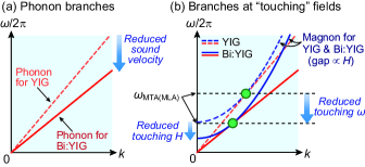
Here, we report SSEs in epitaxially grown BixY3-xFe5O12 (BixY3-xIG with , , and ) films. The BixY3-xIG films may provide an interesting platform to systematically study magnon-polaron anomalies in SSEs, as the films exhibit the enhanced magnetoelastic coupling constant Kumar2019JPCM and the reduced sound velocities by increasing the Bi amount. The former feature leads to an increase in magnon-phonon hybridized region in momentum space (i.e., increase in the anticrossing gap Flebus2017PRB ), and is thus advantageous for magnon-polaron SSEs. The latter feature decreases the magnon-phonon touching fields, since they scale with the sound-velocity squared, as discussed later [, see Eq. (2)]. This situation can also be understood intuitively through a sketch of the magnon-phonon branches at the touching field; as shown in Fig. 1(b), the external required for making the touching condition decreases for Bi:YIG having small compared to YIG. In this paper, we first show structural and magnetic characterization of the epitaxial BixY3-xIG films used in this study and evaluate their sound velocities and magnetoelastic coupling constant (from Sec. III.1 to Sec. III.3). We then show experimental results on the LSSE in the Pt/BixY3-xIG films, where decreased anomaly fields are indeed observed for Bi:YIG (Sec. III.4). We also performed experiments on the SSE in a nonlocal configuration, in which magnon-polaron anomalies appear differently from those in the longitudinal configuration in terms of their sign and intensity (Sec. III.5). Our results show composition-tunability of magnon-polaron anomalies and provide a clue to further understand magnon-polaron SSEs.
II SAMPLE PREPARATION AND EXPERIMENTAL SETUP
We have grown three types of BixY3-xIG films by a liquid phase epitaxy (LPE) method Blank1972LPE ; Simsa1984LPE ; Keszei2001LPE ; Kono2006LPE ; Qiu2013APL ; Qiu2015APEX : YIG, Bi0.5Y2.5IG, and Bi0.9Y2.1IG with the thickness of , , and , respectively. The YIG and Bi0.5Y2.5IG films were grown on (111) planes of 0.5-mm-thick GGG substrates, while the Bi0.9Y2.1IG film was grown on a (111) plane of a 0.7-mm-thick (GdCa)3(GaMgZr)5O12 (substituted-GGG; SGGG) substrate to reduce the lattice mismatch between the film and substrate layers. Here, the lattice constant for cubic YIG (), Bi0.5Y2.5IG (), Bi0.9Y2.1IG (), GGG (), and SGGG () are , , , , and , respectively Chern1997JJAP ; Siu2001PRB . The LPE fabrication for the pure YIG film () was done in PbO-B2O3 flux at the temperature of Qiu2013APL , while that for the BixY3-xIG film with () was done in PbO-Bi2O3-B2O3 flux at (). After the growth, the BixY3-xIG films were cleaned with so-called Piranha etch solution (a mixture of H2SO4 and H2O2 at a ratio of 1:1) and also with acetone in an ultrasonic bath before Pt deposition. The film composition was characterized by an electron probe micro analyzer in the wavelength dispersive mode. The crystallinity and lattice parameters of the BixY3-xIG films were analyzed by means of high-resolution X-ray diffraction (XRD) and transmission electron microcopy (TEM), from which the film thickness was evaluated. The magnetic properties were measured using VSM (vibrating sample magnetometer) option of Physical Property Measurement System (PPMS), Quantum Design Inc.
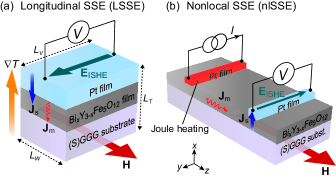
For LSSE measurements, we fabricated 5-nm-thick Pt films on the BixY3-xIG films to electrically detect the SSE voltage based on the inverse spin-Hall effect (ISHE) ISHE_Azevedo ; ISHE_Saitoh ; ISHE_Valenzuela ; ISHE_Costache ; ISHE_Kimura [see Fig. 2(a)]. Here, the Pt films were prepared by ex-situ d.c. magnetron sputtering in a 10-1 Pa Ar atmosphere Nozue2018APL . The samples were cut into a rectangular shape whose length , width , and thickness are, respectively, 4 mm, 2 mm, and 0.5 (0.7) mm for the Pt/YIG/GGG and Pt/Bi0.5Y2.5IG/GGG (Pt/Bi0.9Y2.1IG/SGGG) structures. To apply a temperature difference, , the sample was sandwiched between two sapphire plates; the temperature of the bottom sapphire plate in contact with the (S)GGG substrate is varied in the range from 300 to 3 K, while the temperature of the top sapphire plate placed on the Pt layer is increased by an attached heater Kikkawa2015PRB ; Ito2019PRB . A uniform magnetic field (with the magnitude ) was applied parallel to the film interface [along the direction in Fig. 2(a)] by a superconducting solenoid magnet. We measured the d.c. electric voltage difference between the ends of the Pt films. Hereafter, we plot the LSSE coefficient defined as .
For nonlocal SSE (nlSSE) measurements, we prepared nanofabricated Pt/BixY3-xIG/Pt devices, where two electrically-separated Pt strips with the distance of are formed on the BixY3-xIG films, as schematically shown in Fig. 2(b). Here, Pt strips were prepared by means of electron-beam lithography, followed by Pt sputtering and a lift-off process Cornelissen2017PRB ; Oyanagi2020AIPAdv , whose dimensions are length (), width, and thickness. In our nlSSE setup, the Joule heating of an applied charge current () to the one Pt strip generates a magnon spin current in BixY3-xIG. When some of the magnons reach the other Pt strip, they are converted into a conduction-electron spin current and subsequently detected as an ISHE voltage [see Fig. 2(b)]. We measured the nlSSE using a lock-in detection technique Cornelissen2017PRB ; Oyanagi2020AIPAdv ; Vlietstra2014PRB ; Kikkawa2021NatCommun ; an a.c. charge current at the frequency of 13.423 Hz is applied to the injector Pt strip and a resultant second harmonic nonlocal voltage across the detector Pt strip is measured. Henceforth, we plot the nlSSE coefficient normalized by the applied current squared and the Pt length: Cornelissen2015NatPhys ; Cornelissen2016PRB-H-dep ; Gomez-Perez2020PRB . All the data are obtained in the linear regime Cornelissen2017PRB ; Oyanagi2020AIPAdv , where .
III RESULTS AND DISCUSSION
III.1 Structural characterization
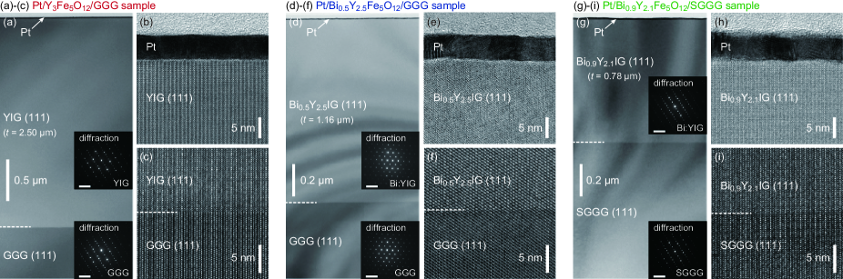
Figure 3 shows the cross-sectional TEM images of the Pt/YIG/GGG, Pt/Bi0.5Y2.5IG/GGG, and Pt/Bi0.9Y2.1IG/SGGG samples. The overall sample cross-section images [Figs. 3(a), 3(d), and 3(g)] show high uniformity and flatness of the films. The high resolution images at the BixY3-xIG/(S)GGG(111) interfaces [Figs. 3(c), 3(f), and 3(i)] reveal atomically smooth and epitaxial interfaces of our garnet films. Neither macroscopic defects nor misalignment in the lattice planes were observed in TEM images. As shown in the insets of Figs. 3(a), 3(d), and 3(g), the diffraction patterns of the BixY3-xIG films coincide with those of the (S)GGG substrates, indicating that the BixY3-xIG layers are grown as single-crystalline films with the [111] orientation in the out-of-plane direction. We also confirmed clear interfaces between the (polycrystalline) Pt-film and BixY3-xIG-film contacts [see Figs. 3(b), 3(e), and 3(h)], which allows us to investigate interfacial spin-current transport in these sample systems.
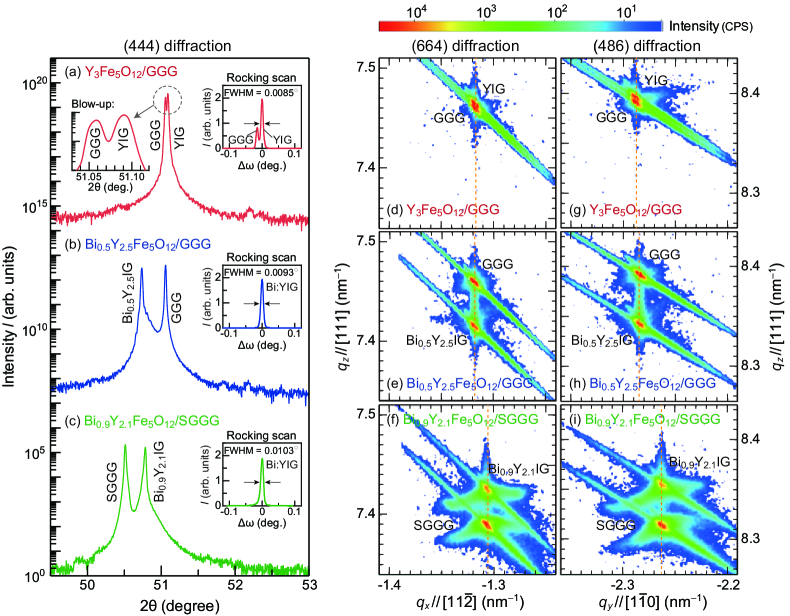
Figures 4(a), 4(b), and 4(c) display the - XRD patterns of the BixY3-xIG films around the (444) Bragg peaks from the GGG () or SGGG () substrates. For all the samples, we observed the (444) diffraction peaks from the BixY3-xIG layer, confirming the out-of-plane orientation of BixY3-xIG[111]/(S)GGG[111], consistent with the TEM results shown in Fig. 3. The XRD rocking curves exhibit full width at half maximum (FWHM) values of , , and for the YIG, Bi0.5Y2.5IG, and Bi0.9Y2.1IG, respectively, which are close to the values for the substrates ( for GGG and for SGGG), ensuring high crystalline quality of our films.
To further characterize structural properties of the films, we performed reciprocal space mapping (RSM) Kubota2012APEX ; Kubota2013JMMM ; Avci2017NatMat . Figures 4(d), 4(e), 4(f) show the RSM data around the (664) diffraction for the YIG/GGG, Bi0.5Y2.5IG/GGG, and Bi0.9Y2.1IG/SGGG samples, respectively. For all the samples, the asymmetric diffraction peaks lie on one vertical line, indicating that the films have a pseudomorphic structure with the in-plane lattice constant identical to that of the substrate along the direction Kubota2012APEX ; Kubota2013JMMM ; Avci2017NatMat . The pseudomorphic structure was confirmed also along the direction by the RSM data for the (486) diffraction [see Figs. 4(g), 4(h), and 4(i)].
From the XRD and RSM results, the out-of-plane (in-plane) lattice constant was estimated to be () for the YIG film on GGG, () for the Bi0.5Y2.5IG film on GGG, and () for the Bi0.9Y2.1IG film on SGGG. This result shows that the YIG film grown on GGG is nearly free from strain, while the Bi0.5Y2.5IG (Bi0.9Y2.1IG) film grown on GGG (SGGG) has compressive (tensile) epitaxial strain. In TABLE 1, we show the in-plane biaxial strain and out-of-plane uniaxial strain values evaluated according to Ref. Kubota2013JMMM, . The in-plane stress values Kubota2013JMMM are also calculated using the elastic coefficients ; : mass density) and and the relation Gurevich-Melkov_text ; YIG_Paoletti_text , which we list also in TABLE 1.
| Sample | |||||||
|---|---|---|---|---|---|---|---|
| (%) | (%) | (GPa) | () | () | () | (THz) | |
| Y3Fe5O12 | |||||||
| Bi0.5Y2.5Fe5O12 | |||||||
| Bi0.9Y2.1Fe5O12 |
III.2 Magnetic characterization
In Figs. 5(a), 5(b), and 5(c), we show the magnetic field dependence of the magnetization of the (a) YIG, (b) Bi0.5Y2.5IG, and (c) Bi0.9Y2.1IG films, respectively. Here, the - curves are recorded at under the applied parallel to the in-plane (solid lines) and to the out-of-plane (dashed lines) axes. The pure YIG film (nearly free from strain) has an in-plane easy axis due to the shape anisotropy and negligibly-small magnetocrystalline anisotropy Kubota2013JMMM ; SSE_Kikkawa2013PRL ; Gallagher2016APL ; the saturation field value for the in-plane field () is much smaller than that for the out-of-plane field () [see Fig. 5(a)]. The in-plane saturation field for the Bi0.5Y2.5IG (Bi0.9Y2.1IG) film is estimated to be (0.17 T), which is much smaller (slightly higher) than that for the out-of-plane () [see Figs. 5(b) and 5(c)]. The different v.s features can be interpreted in terms of the stress-induced anisotropy; for a material with a negative magnetostriction constant such as BixY3-xIG, the magnetic easy axis tends to lie in (perpendicular to) the film plane for compressive (tensile) epitaxial strain Hansen1983PRB ; Kubota2012APEX ; Kubota2013JMMM ; Tang2016PRB ; Fu2017APL . Therefore, for the Bi0.5Y2.5IG films on GGG with the compressive epitaxial strain, both the shape anisotropy and stress-induced anisotropy make the magnetic easy axis within an in-plane direction (). In contrast, for the Bi0.9Y2.1IG film on SGGG with the tensile epitaxial strain, the stress-induced out-of-plane anisotropy appears and prevails against the shape anisotropy, which renders the magnetic easy axis perpendicular to the film plane () Soumah2018NatCommun .
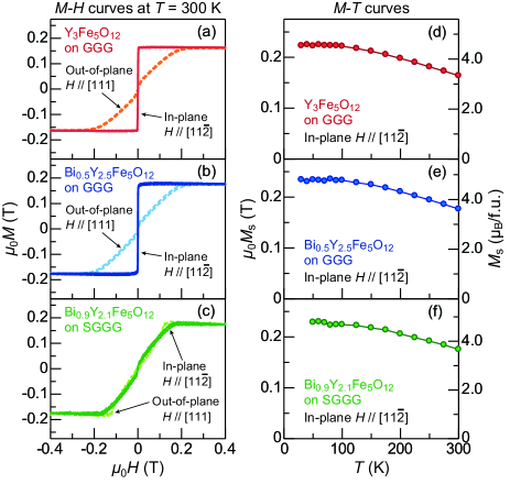
The saturation magnetization values were estimated to be (), (), and () at , for the YIG, Bi0.5Y2.5IG, and Bi0.9Y2.1IG films, respectively, in units of the Bohr magneton (Tesla) (see Fig. 5). The value increases by the Bi substitution, which is consistent with the previous reports Hansen1983PRB ; Hansen1984ThinSolidFilms . Figures 5(d), 5(e), and 5(f) show the dependence of of the (d) YIG, (e) Bi0.5Y2.5IG, and (f) Bi0.9Y2.1IG films, respectively, for the direction parallel to the in-plane axis. For all the samples, the value increases with decreasing and approaches to at the lowest , showing good agreement with the theoretical and previous experimental results YIG_Gilleo-Geller ; Hansen1983PRB ; Hansen1984ThinSolidFilms ; Kikkawa2017PRB .
III.3 Evaluation of sound velocity and magnetoelastic coupling
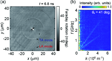
To determine the sound velocities of the BixY3-xIG films, we employed a pump-and-probe magneto-optical imaging method combined with a Fourier transform (FT) process (see Refs. Hashimoto2017NatCommun, and Hashimoto2018PRB, for the details of the optical system in this experiment). When a pumped laser pulse with a spot radius of is irradiated to the sample, elastic waves are excited and propagate radially from the excitation point. Via the magnetoelastic interaction, the elastic waves tilt the magnetic moments from an in-plane to out-of-plane direction that can be detected as a change of the Faraday rotation angle of the probe pulse Hashimoto2017NatCommun ; Hashimoto2018PRB . Figure 6(a) shows a snapshot of the temporal evolution of out-of-plane magnetization distribution of the Bi0.9Y2.1IG sample obtained at the time delay of ns between the pump and probe pulses. Two ring structures are visible; the inner (outer) ring is attributed to the coupled TA (LA) and spin waves having a smaller (larger) velocity. By Fourier transforming the observed propagating waveform with respect to the time and spatial coordinates, we obtain coupled phonon and spin waves dispersion relations. As shown in Fig. 6(b), two -linear dispersions with different slopes are discerned; the dispersion showing the lower (larger) slope is assigned to the TA (LA) phonon branch, from which we can estimate the sound velocities of each phonon mode. Measurements were performed also for the Bi0.5Y2.5IG sample. We note that the crossings between phonon and spin wave branches are inaccessible, since their positions in the momentum direction are large and therefore out of range in the present experiment.
Significant decreases in the sound velocities for the Bi:YIG films are indeed confirmed through the above measurements and analysis. As shown in Table 1, the TA- and LA-phonon sound velocities of the Bi0.5Y2.5IG films were determined to be and , giving values smaller than those of YIG. For the Bi0.9Y2.1IG film, and , showing the smallest values among our samples.
Using the magnetostriction constant values for m-thick BixY3-xIG films [] shown in Ref. Soumah2018NatCommun, and the sound velocities in Table 1, the magnetoelastic coupling constant (: lattice constant) Kittel1949RevModPhys ; Gurevich-Melkov_text ; YIG_Paoletti_text was estimated to be , , and for the YIG, Bi0.5Y2.5IG, and Bi0.9Y2.1IG films, respectively. The value monotonically increases by increasing the Bi amount , which may be attributed to the enhanced spin-orbit coupling induced by the substitution of Bi3+ ions Kumar2019JPCM .
III.4 Magnon-polaron features in LSSE
Now, we present the experimental results on the LSSE in the Pt/BixY3-xIG samples. Figure 7(a) shows the dependence of the LSSE coefficient of the Pt/YIG sample measured at . In this conventional system, we observed a clear SSE signal as well as two magnon-polaron-induced spikes on top of the almost flat background signal [see the blue and red filled triangles in Fig. 7(a) and magnified view shown in Fig. 7(d)]. The peak at the lower (higher) appears at (), consistent with Ref. Kikkawa2016PRL, . The and values coincide with the intensities at which the magnon dispersion curve touches the TA- and LA-phonon dispersion curves of YIG, respectively, being the conditions that the magnon and phonon modes can be coupled over the largest volume in momentum space, so the magnon-polaron effects are maximized Kikkawa2016PRL ; Flebus2017PRB .
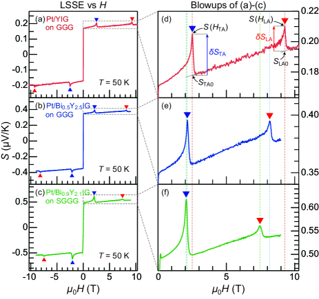
Next, let us focus on the effect of Bi substitution on the LSSE and magnon-polaron features. Figures 7(b) and 7(c) show the dependence of of the Pt/Bi0.5Y2.5IG and Pt/Bi0.9Y2.1IG samples, respectively. We observed SSE signals in these samples, of which the amplitudes are comparable to that for the Pt/YIG shown in Fig. 7(a). The peak features show up also in these Pt/Bi:YIG systems as marked by the blue and red filled triangles in Figs. 7(b) and 7(c). Interestingly, the peak positions shift toward lower values by increasing the amount of Bi substitution. The peak positions at the lower and higher for the Pt/Bi0.5Y2.5IG sample are estimated to be and , respectively. For the Pt/Bi0.9Y2.1IG, the peak fields are further decreased: and .
The observed peak shifts are explained in terms of the reduction of the sound velocities and resultant touching fields of Bi:YIG films. The touching field can be evaluated quantitatively by solving the combined equation for the magnon () and phonon () dispersion relations and their group velocities:
| (1) |
where the magnon dispersion relation, disregarding the dipolar interaction (), reads , while the phonon dispersions are given by . Here, , , and represent the exchange stiffness, wavenumber, and gyromagnetic ratio, respectively. Calculation of Eq. (1) leads to
| (2) |
which shows that the touching field scales quadratically with the sound velocity , and so does the anomaly field in the SSE. In fact, the observed peak fields are well reproduced by the sound velocities shown in Table 1 and reasonable values of , , and for the YIG, Bi0.5Y2.5IG, and Bi0.9Y2.1IG, respectively. The frequency value for the touching point () between the magnon and TA(LA)-phonon branches at (), depicted as green filled circles in Fig. 1(b), can be evaluated as () for the YIG, () for the Bi0.5Y2.5IG, and () for the Bi0.9Y2.1IG.
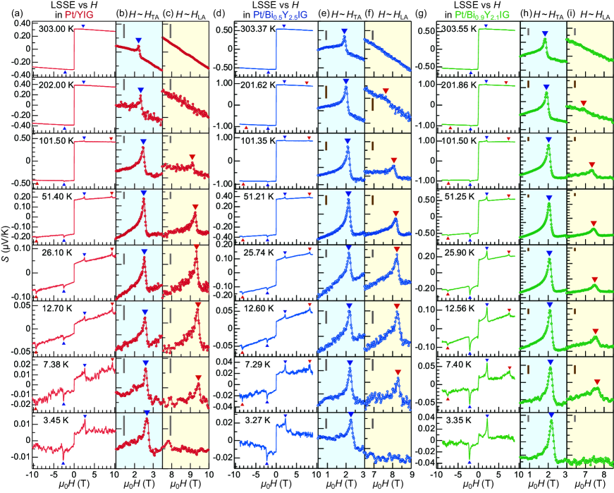
We carried out systematic measurements of the temperature dependence of the LSSE in these Pt/BixY3-xIG samples. Figures 8(a), 8(d), and 8(g) show the - curves for the various average sample temperature (from to ) for the Pt/YIG, Pt/Bi0.5Y2.5IG, and Pt/Bi0.9Y2.1IG samples, respectively. In all the samples, the overall dependences of agree with those for the Pt/YIG-film samples reported in Refs. Kikkawa2015PRB, and Jin2015PRB, ; when the sample temperature is decreased from , the magnitude of increases and shows a broad peak at around [see Figs. 9(a)-9(c)]. On decreasing further, the signal begins to decrease and eventually goes to zero.
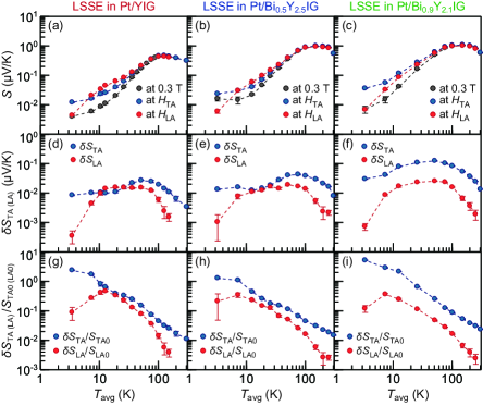
We now discuss the dependence of the magnon-polaron features in the LSSE. First, let us focus on the results at a low- range below , at which characteristic response is expected to occur due to the competition between the thermal energy and the magnon-polaron’s touching energy , which governs the dependence of thermal occupation of magnon-polaron modes Kikkawa2016PRL . Figures 9(d), 9(e), and 9(f) represent the dependence of the magnon-polaron peak amplitude for the Pt/YIG, Pt/Bi0.5Y2.5IG, and Pt/Bi0.9Y2.1IG samples, respectively, where is the extrapolated background at the peak position [see also the definition shown in Fig. 7(d) and its caption]. The peak intensities at and exhibit different dependences. We further introduce and hereafter discuss the quantity , where is normalized by the background , which allows us to evaluate the -dependence of the magnon-polaron SSE coefficient relative to the background magnonic one at and also to exclude common -dependent factors in the magnon-polaron and magnonic SSE voltages such as the interfacial spin conductance, electric resistance, and spin diffusion length in the Pt film Cornelissen2016PRB-chemical-potential ; Guo2016PRX ; Cornelissen2017PRB . As shown in Figs. 9(g)-9(i), monotonically increases with decreasing and takes a maximum value at the lowest for all the samples (see also the - curves shown in Fig. 8). In contrast, , is gradually suppressed below () for the Pt/YIG sample (Pt/Bi0.5Y2.5IG and Pt/Bi0.9Y2.1IG samples) [see Figs. 8 and 9(g)-9(i)]. At the lowest , the peak at is so small and almost indistinguishable from the background [see Figs. 8(c), 8(f), and 8(i)]. The -dependent feature can be interpreted in terms of the difference in the frequency values of the branch touching point for and for [see Fig. 1(b)] Kikkawa2016PRL ; Flebus2017PRB . Here, in the unit of temperature, the values approximately correspond to , , and for the YIG, Bi0.5Y2.5IG, and Bi0.9Y2.1IG, respectively, and they are more than 3 times greater than those of the values (, , and , respectively). Therefore, for , the excitation of magnon polarons at the touching frequency is rapidly suppressed, which leads to the disappearance of the peak at at the lowest . Furthermore, the reduction of values for Bi0.5Y2.5IG and Bi0.9Y2.1IG, by a value of , compared to that for the YIG may be responsible for the difference of the onset values between the Pt/Bi:YIG () and Pt/YIG (), at which starts to be suppressed with decreasing .
Next, we move on to the results at a higher- range (). In this range, we are also able to resolve small but finite peak structures at for all the samples, while, at , the peak structures were detectable below () for the Pt/YIG (Pt/Bi:YIG) sample (see Figs. 8 and 9). As shown in Figs. 9(g)-9(i), the peak amplitudes at and relative to the background SSE signals, and , monotonically decrease with increasing , which may be due to the appearance of large contributions of thermally populated (uncoupled) magnons with the energy of to the background SSE signal. Furthermore, the observed structures with only peak shapes (no dip shapes) suggest that the scattering rate of magnons with the frequencies relevant to the hybridization (i.e., ) are always larger than that of phonons at all the range: Kikkawa2016PRL ; Flebus2017PRB . We also found that, in this range, as the temperature is increased, the value decreases much faster than the value for all the samples [see Figs. 9(g)-9(i)]. We note that with increasing , dominant scattering sources for magnons and phonons may change from disorders (impurities) to inelastic magnon-magnon and phonon-phonon scatterings due to their increased thermal population Rezende2014PRB ; Cornelissen2016PRB-chemical-potential ; Boona2014PRB ; Shi2021PRL_YIG-bulk ; Schmidt2018PRB . A detailed knowledge on the and dependences of such scattering events for the BixY3-xIG films will thus be important to fully understand the observed behavior.
Finally, we compare the amplitudes of the peak structures in the LSSE in the Pt/BixY3-xIG samples. The magnon-polaron contribution at for the Pt/YIG, Pt/Bi0.5Y2.5IG, and Pt/Bi0.9Y2.1IG samples at the lowest () was evaluated as 2.4, 1.3, and 5.2 (0.15, 0.11, and 0.25), respectively. This nonmonotonic dependence with respect to the Bi amount is not simply explained by the magnetoelastic coupling constant , since it monotonically increases by increasing the Bi substitution (see TABLE 1). Although larger values should be beneficial for the magnon-polaron formation and resultant SSE anomalies, our results suggest that the scattering ratio parameterized by may play a rather important role for the comparison of the magnon-polaron peak intensities between each sample. Furthermore, in the LSSE results, we found that the magnon-polaron contribution at is greater than that at , i.e., for all the range and all the samples [see Figs. 9(g)-9(i)]. This tendency is compared with that for the nlSSE results in the next section.
III.5 Magnon-polaron features in nlSSE
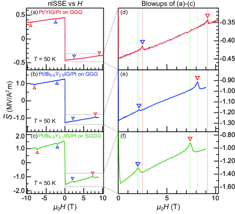
We now show the results on the nlSSE in the Pt/BixY3-xIG/Pt systems. Figures 10(a), 10(b), and 10(c) show the dependence of the nlSSE coefficient of the Pt/YIG/Pt, Pt/Bi0.5Y2.5IG/Pt, and Pt/Bi0.9Y2.1IG/Pt samples measured at , respectively. The overall signal appears with a sign opposite to that for the LSSE, indicating that thermally-excited magnons accumulate beneath the detector Pt strip. The observed sign is indeed a characteristic in nlSSEs for m-thick garnet films with a long injector-detector separation distance ( in the present case) Cornelissen2017PRB ; Shan2016PRB ; Shan2017PRB . As marked by the blue and red unfilled triangles in the nlSSE signals in Fig. 10, magnon-polaron induced anomalies are also observed at the touching fields , which shift toward lower values by increasing the Bi amount [see also the magnified views for shown in Figs. 10(d), 10(e), and 10(f)]. The values are evaluated as () for the Pt/YIG/Pt, () for the Pt/Bi0.5Y2.5IG/Pt, and () for the Pt/Bi0.9Y2.1IG/Pt, in good agreement with those estimated from the LSSE results. For the nlSSE, the magnon-polaron formation decreases rather than increases the signal at the touching fields , causing dip structures (note that the background nlSSE signal is opposite in sign compared to that for the LSSECornelissen2017PRB ; Shan2018APL ; Oyanagi2020AIPAdv ). In Ref. Cornelissen2017PRB, , the dip feature is discussed in terms of the competition between a temperature-gradient induced magnon current, , from the injector to detector and a diffusive backflow, , induced by the gradient of the magnon chemical potential [ and in the coordinate system shown in Fig. 2(b)], which are both increased by the hybridization with phonons when Cornelissen2017PRB ; Flebus2017PRB . In particular, assuming that the magnon spin conductivity is more strongly increased than the bulk SSE coefficient via the magnon-polaron formation, the increased backflow of magnons toward the injector direction causes the reduction of magnon accumulation beneath the Pt detector, which leads to the suppression of the nlSSE at the touching fields Cornelissen2017PRB .
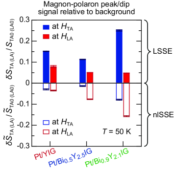
Through a careful look at the magnon-polaron anomalies in Fig. 10, we notice that the intensity of the anomaly at is larger than that at in the nlSSE for all the samples: . The values at are evaluated to be () for the Pt/YIG/Pt, () for the Pt/Bi0.5Y2.5IG/Pt, and () for the Pt/Bi0.9Y2.1IG/Pt at , which we summarize in Fig. 11. The observed relationship for the nlSSE, , holds in a wide range for , and is opposite to that for the LSSE results, where (see Fig. 11 and also Figs. S1 and S2 in the Supplemental Material SM for the dependence of the nlSSE). In the following, we discuss possible origins of the anisotropic feature. One possible scenario is a spectral non-uniform magnon current Kikkawa2015PRB ; Schmidt2021PRB that may vary depending on the experimental configurations; the frequency-resolved current at may be larger (smaller) than at for the longitudinal (nonlocal) configuration. In Refs. Kikkawa2015PRB, , Oyanagi2020AIPAdv, and Jin2015PRB, , through high- dependence experiments and its comparison with theory, a spectral non-uniformity in a magnon current is suggested to be present in both LSSEs and nlSSEs due to the frequency-dependent magnon scattering time Schmidt2021PRB ; Streib2019PRB . Moreover, in the present case, as shown in Figs. 7 and 10, the high- response of the background SSEs in the longitudinal and nonlocal configurations differs with each other. This may be a signature that the frequency-dependent contribution is different between the LSSE and nlSSE. Another possibility would be the anisotropy in magnon and magnon-polaron dispersion relations due to the nature of the dipole and magnetoelastic interaction Shen2015PRL ; Flebus2017PRB , which depend on the magnon propagation direction () relative to the external magnetic field . In the LSSE, is essentially perpendicular to , while in the nlSSE parallel to in the one-dimensional limit (see Fig. 2). Therefore, the LSSE and nlSSE may be affected by the anisotropic dispersion relations in a different manner. In fact, a solution of a Boltzmann transport equation shows that, for (compatible with the LSSE), the magnon-polaron anomaly at is larger than that at , while, for (compatible with the nlSSE in the one-dimensional limit), the anomaly at is smaller than that at Flebus2017PRB . This is consistent with our experimental results, and suggests that the anisotropic nature of magnon and magnon-polaron dispersion relations may affect the SSEs. It is worth mentioning that the profile of the temperature gradient created by the local Pt heater in the nonlocal configuration may be affected by size effects Cornelissen2017PRB ; Shan2016PRB ; Shan2017PRB , such as the thickness of the magnetic layer and the size of the local heater. Future systematic measurements of the Bi:YIG thickness, heater size, and injector-detector separation distance () dependencies may provide useful information to understand possible roles of the size effects in the anisotropic feature of magnon-polaron signals. Besides, the magnon-polaron formation can also affect the magnon and phonon thermal conductivities Flebus2017PRB , which may modify the temperature gradient and resultant spin-current intensity at the onset field of magnon-polaron formation. The process, which has not been considered in analysis so far, would be important for further quantitative argument on the magnon-polaron anomalies in SSEs.
IV CONCLUSION
To summarize, we have prepared LPE-grown single crystalline BixY3-xFe5O12 (BixY3-xIG; , , and ) films with Pt contact and measured SSEs in both the longitudinal and nonlocal configurations. We observed two anomalous peaks in -dependent LSSE signals at the onset fields for the magnon-polaron formation at which the magnon and TA,LA-phonon branches in BixY3-xIG touch with each other. The anomaly fields shift toward lower values by increasing the Bi amount , which is attributed to the reduction of the sound velocities of BixY3-xIG by the Bi substitution. The observed peak behavior at the wide temperature range from 3 to 300 K suggests that the scattering rate of magnons is larger than that of phonons in all our sample systems Flebus2017PRB . In the nlSSE measurements, we found that the magnon-polaron formation suppresses rather than enhances the signal, causing dip structures at the touching fields for the BixY3-xIG films, consistent with the previous studies Cornelissen2017PRB ; Shan2018APL ; Oyanagi2020AIPAdv . We further found that the intensities of magnon-polaron anomalies in the nlSSE appear to be different from those in the LSSE, although the anomaly fields are almost identical for both the configurations. We anticipate that our detailed temperature and magnetic-field dependent SSE results provide useful information to further elucidate the physics of magnon-polaron SSEs.
ACKNOWLEDGMENTS
The authors thank S. Ito and Y. Murakami from Institute for Materials Research, Tohoku University, for performing transmission electron microscopy and electron probe microanalysis on our samples, respectively. This work was supported by ERATO “Spin Quantum Rectification Project” (No. JPMJER1402) and CREST (Nos. JPMJCR20C1 and JPMJCR20T2) from JST, Japan, Grant-in-Aid for Scientific Research (JP19H05600, JP20H02599, JP20K22476, JP21K14519, JP22K14584, and JP22K18686) and Grant-in-Aid for Transformative Research Areas (No. JP22H05114) from JSPS KAKENHI, Japan, NEC Corporation, and Institute for AI and Beyond of the University of Tokyo. Z.Q. acknowledges support from the National Natural Science Foundation of China (Grants No. 11874098 and No. 52171173). R.R. acknowledges support from the European Commission through the project 734187-SPICOLOST (H2020-MSCA-RISE-2016), the European Union’s Horizon 2020 research and innovation program through the MSCA grant agreement SPEC-894006, Grant RYC 2019-026915-I funded by the MCIN/AEI/ 10.13039/501100011033 and by ”ESF investing in your future”, the Xunta de Galicia (ED431B 2021/013, Centro Singular de Investigación de Galicia Accreditation 2019-2022, ED431G 2019/03) and the European Union (European Regional Development Fund - ERDF).
References
- (1) P. Hansen, K. Witter, and W. Tolksdorf, Magnetic and magneto-optic properties of lead- and bismuth-substituted yttrium iron garnet films, Phys. Rev. B 27, 6608 (1983).
- (2) P. Hansen and J.-P. Krumme, Magnetic and magneto-optical properties of garnet films, Thin Solid Films 114, 69 (1984).
- (3) R. Kumar, B. Samantaray, and Z. Hossain, Ferromagnetic resonance studies of strain tuned Bi:YIG films, J. Phys.: Condens. Matter 31, 435802 (2019).
- (4) L. Soumah, N. Beaulieu, L. Qassym, C. Carrétéro, E. Jacquet, R. Lebourgeois, J. Ben Youssef, P. Bortolotti, V. Cros, and A. Anane, Ultra-low damping insulating magnetic thin films get perpendicular, Nat. Commun. 9, 3355 (2018).
- (5) M. Evelt, L. Soumah, A. B. Rinkevich, S. O. Demokritov, A. Anane, V. Cros, J. Ben Youssef, G. de Loubens, O. Klein, P. Bortolotti, and V. E. Demidov, Emission of Coherent Propagating Magnons by Insulator-Based Spin-Orbit-Torque Oscillators, Phys. Rev. Applied 10, 041002 (2018).
- (6) A. V. Chumak et al., Advances in Magnetics Roadmap on Spin-Wave Computing, IEEE Trans. Magn. 58, 0800172 (2022).
- (7) P. X. Zhang, D. J. Lockwood, and H. J. Labbé, Magnon and acoustic-phonon light scattering from Bi-doped yttrium iron garnet, Phys. Rev. B 48, 6099 (1993).
- (8) G. G. Siu, C. M. Lee, and Y. Liu, Magnons and acoustic phonons in Y3-xBixFe5O12, Phys. Rev. B 64, 094421 (2001).
- (9) L. Dreher, M. Weiler, M. Pernpeintner, H. Huebl, R. Gross, M. S. Brandt, and S. T. B. Goennenwein, Surface acoustic wave driven ferromagnetic resonance in nickel thin films: Theory and experiment, Phys. Rev. B 86, 134415 (2012).
- (10) N. Ogawa, W. Koshibae, A. J. Beekman, N. Nagaosa, M. Kubota, M. Kawasaki, and Y. Tokura, Photodrive of magnetic bubbles via magnetoelastic waves, Proc. Natl. Acad. Sci. U.S.A. 112, 8977 (2015).
- (11) K. Shen and G. E. W. Bauer, Laser-induced spatiotemporal dynamics of magnetic films, Phys. Rev. Lett. 115, 197201 (2015).
- (12) S. C. Guerreiro and S. M. Rezende, Magnon-phonon interconversion in a dynamically reconfigurable magnetic material, Phys. Rev. B 92, 214437 (2015).
- (13) T. Kikkawa, K. Shen, B. Flebus, R. A. Duine, K. Uchida, Z. Qiu, G. E. W. Bauer, and E. Saitoh, Magnon polarons in the spin Seebeck effect, Phys. Rev. Lett. 117, 207203 (2016).
- (14) D. A. Bozhko, P. Clausen, G. A. Melkov, V. S. L’vov, A. Pomyalov, V. I. Vasyuchka, A. V. Chumak, B. Hillebrands, and A. A. Serga, Bottleneck accumulation of hybrid magnetoelastic bosons, Phys. Rev. Lett. 118, 237201 (2017).
- (15) Y. Hashimoto, S. Daimon, R. Iguchi, Y. Oikawa, K. Shen, K. Sato, D. Bossini, Y. Tabuchi, T. Satoh, B. Hillebrands, G. E. W. Bauer, T. H. Johansen, A. Kirilyuk, Th. Rasing, and E. Saitoh, All-optical observation and reconstruction of spin wave dispersion, Nat. Commun. 8, 15859 (2017).
- (16) J. Holanda, D. S. Maior, A. Azevedo, and S. M. Rezende, Detecting the phonon spin in magnon-phonon conversion experiments, Nat. Phys. 14, 500–506 (2018).
- (17) Y. Hashimoto, D. Bossini, T. H. Johansen, E. Saitoh, A. Kirilyuk, and T. Rasing, Frequency and wavenumber selective excitation of spin waves through coherent energy transfer from elastic waves, Phys. Rev. B 97, 140404(R) (2018).
- (18) H. Hayashi and K. Ando, Spin pumping driven by magnon polarons, Phys. Rev. Lett. 121, 237202 (2018).
- (19) R. Yahiro, T. Kikkawa, R. Ramos, K. Oyanagi, T. Hioki, S. Daimon, and E. Saitoh, Magnon polarons in the spin Peltier effect, Phys. Rev. B 101, 024407 (2020).
- (20) K. An, A. N. Litvinenko, R. Kohno, A. A. Fuad, V. V. Naletov, L. Vila, U. Ebels, G. de Loubens, H. Hurdequint, N. Beaulieu, J. Ben Youssef, N. Vukadinovic, G. E. W. Bauer, A. N. Slavin, V. S. Tiberkevich, and O. Klein, Coherent long-range transfer of angular momentum between magnon Kittel modes by phonons, Phys. Rev. B 101, 060407(R) (2020).
- (21) F. Godejohann, A. V. Scherbakov, S. M. Kukhtaruk, A. N. Poddubny, D. D. Yaremkevich, M. Wang, A. Nadzeyka, D. R. Yakovlev, A. W. Rushforth, A. V. Akimov, and M. Bayer, Magnon polaron formed by selectively coupled coherent magnon and phonon modes of a surface patterned ferromagnet, Phys. Rev. B 102 144438 (2020).
- (22) T. Hioki, Y. Hashimoto, and E. Saitoh, Bi-reflection of spin waves, Commun. Phys. 3, 188 (2020).
- (23) P. Frey, D. A. Bozhko, V. S. L’vov, B. Hillebrands, and A. A. Serga, Double accumulation and anisotropic transport of magnetoelastic bosons in yttrium iron garnet films, Phys. Rev. B 104, 014420 (2021).
- (24) J. Zhang, M. Chen, J. Chen, K. Yamamoto, H. Wang, M. Hamdi, Y. Sun, K. Wagner, W. He, Y. Zhang, J. Ma, P. Gao, X. Han, D. Yu, P. Maletinsky, J.-P. Ansermet, S. Maekawa, D. Grundler, C.-W. Nan, and H. Yu, Long decay length of magnon-polarons in BiFeO3/La0.67Sr0.33MnO3 heterostructures, Nat. Commun. 12, 7258 (2021).
- (25) R. Schlitz, L. Siegl, T. Sato, W. Yu, G. E. W. Bauer, H. Huebl, and S. T. B. Goennenwein, Magnetization dynamics affected by phonon pumping, Phys. Rev. B 106, 014407 (2022).
- (26) B. Flebus, K. Shen, T. Kikkawa, K. Uchida, Z. Qiu, E. Saitoh, R. A. Duine, and G. E. W. Bauer, Magnon-polaron transport in magnetic insulators, Phys. Rev. B 95, 144420 (2017).
- (27) K. Uchida, H. Adachi, T. Ota, H. Nakayama, S. Maekawa, and E. Saitoh, Observation of longitudinal spin-Seebeck effect in magnetic insulators, Appl. Phys. Lett. 97, 172505 (2010).
- (28) K. Uchida, M. Ishida, T. Kikkawa, A. Kirihara, T. Murakami, and E. Saitoh, Longitudinal spin Seebeck effect: from fundamentals to applications, J. Phys.: Condens. Matter 26, 343202 (2014)., ibid. 26, 389601 (2014).
- (29) K. Uchida, H. Adachi, T. Kikkawa, A. Kirihara, M. Ishida, S. Yorozu, S. Maekawa, and E. Saitoh, Thermoelectric generation based on spin Seebeck effects, Proc. IEEE 104, 1946 (2016)., ibid. 104, 1499 (2016).
- (30) T. Kikkawa and E. Saitoh, Spin Seebeck Effect: Sensitive Probe for Elementary Excitation, Spin Correlation, Transport, Magnetic Order, and Domains in Solids, to appear in Vol. 14 of Annu. Rev. Condens. Matter Phys. (2023)., arXiv:2205.10509 (2022).
- (31) H. Wang, D. Hou, T. Kikkawa, R. Ramos, K. Shen, Z. Qiu, Y. Chen, M. Umeda, Y. Shiomi, X. Jin, and E. Saitoh, The bimodal distribution spin Seebeck effect enhancement in epitaxial Ni0.65Zn0.35Al0.8Fe1.2O4 thin film, Appl. Phys. Lett. 112, 142406 (2018).
- (32) R. Ramos, T. Hioki, Y. Hashimoto, T. Kikkawa, P. Frey, A. J. E. Kreil, V. I. Vasyuchka, A. A. Serga, B. Hillebrands, and E. Saitoh, Room temperature and low-field resonant enhancement of spin Seebeck effect in partially compensated magnets, Nat. Commun. 10, 5162 (2019).
- (33) W. Xing, Y. Ma, Y. Yao, R. Cai, Y. Ji, R. Xiong, K. Shen, and W. Han, Facet-dependent magnon-polarons in epitaxial ferrimagnetic Fe3O4 thin films, Phys. Rev. B 102, 184416 (2020).
- (34) J. Li, H. T. Simensen, D. Reitz, Q. Sun, W. Yuan, C. Li, Y. Tserkovnyak, A. Brataas, and J. Shi, Observation of magnon polarons in a uniaxial antiferromagnetic insulator, Phys. Rev. Lett. 125, 217201 (2020).
- (35) B. Yang, S. Y. Xia, H. Zhao, G. Liu, J. Du, K. Shen, Z. Qiu, and D. Wu, Revealing thermally driven distortion of magnon dispersion by spin Seebeck effect in Gd3Fe5O12, Phys. Rev. B 103, 054411 (2021).
- (36) Z. Shi, Q. Xi, J. Li, Y. Li, M. Aldosary, Y. Xu, J. Zhou, S.-M. Zhou, and J. Shi, Role of magnon-magnon scattering in magnon polaron spin Seebeck effect, Phys. Rev. Lett. 127, 277203 (2021).
- (37) S. L. Blank and J. W. Nielsen, The growth of magnetic garnets by liquid phase epitaxy, J. Cryst. Growth 17, 302 (1972).
- (38) Z. Šimša, J. Šimšová D. Zemanová, J. Čermák, and M. Nevřiva, Correlation between Faraday rotation and bismuth and lead contents in LPE YIG films, Czech. J. Phys. 34, 1102 (1984).
- (39) B. Keszei, Z. Vértesy, and G. Vértesy, Growth of Bi and Ga Substituted YIG and LuIG Layers by LPE Method, Cryst. Res. Technol. 36, 953 (2001).
- (40) T. Kono, T. Machi, N. Chikumoto, K. Nakao, N. Koshizuka, N. Adachi, and T. Okuda, LPE growth of bismuth substituted iron garnet films with in-plane magnetization, J. Magn. Soc. Japan 30, 600 (2006).
- (41) Z. Qiu, K. Ando, K. Uchida, Y. Kajiwara, R. Takahashi, H. Nakayama, T. An, Y. Fujikawa, and E. Saitoh, Spin mixing conductance at a well-controlled platinum/yttrium iron garnet interface, Appl. Phys. Lett. 103, 092404 (2013).
- (42) Z. Qiu, D. Hou, T. Kikkawa, K. Uchida, and E. Saitoh, All-oxide spin Seebeck effects, Appl. Phys. Express 8, 083001 (2015).
- (43) M.-Y. Chern and J.-S. Liaw, Study of BixY3-xFe5O12 thin films grown by pulsed laser deposition, Jpn. J. Appl. Phys. 36, 1049 (1997).
- (44) A. Azevedo, L. H. Vilela-Leão, R. L. Rodríguez-Suárez, A. B. Oliveira, and S. M. Rezende, dc effect in ferromagnetic resonance: Evidence of the spin-pumping effect?, J. Appl. Phys. 97, 10C715 (2005).
- (45) E. Saitoh, M. Ueda, H. Miyajima, and G. Tatara, Conversion of spin current into charge current at room temperature: Inverse spin-Hall effect, Appl. Phys. Lett. 88, 182509 (2006).
- (46) S. O. Valenzuela and M. Tinkham, Direct electronic measurement of the spin Hall effect, Nature 442, 176 (2006).
- (47) M. V. Costache, M. Sladkov, S. M. Watts, C. H. van der Wal, and B. J. van Wees, Electrical detection of spin pumping due to the precessing magnetization of a single ferromagnet, Phys. Rev. Lett. 97, 216603 (2006).
- (48) T. Kimura, Y. Otani, T. Sato, S. Takahashi, and S. Maekawa, Room-temperature reversible spin Hall effect, Phys. Rev. Lett. 98, 156601 (2007).
- (49) T. Nozue, T. Kikkawa, T. Watamura, T. Niizeki, R. Ramos, E. Saitoh, and H. Murakami, Fabrication of yttrium-iron-garnet/Pt multilayers for the longitudinal spin Seebeck effect, Appl. Phys. Lett. 113, 262402 (2018).
- (50) T. Kikkawa, K. Uchida, S. Daimon, Z. Qiu, Y. Shiomi, and E. Saitoh, Critical suppression of spin Seebeck effect by magnetic fields, Phys. Rev. B 92, 064413 (2015).
- (51) N. Ito, T. Kikkawa, J. Barker, D. Hirobe, Y. Shiomi, and E. Saitoh, Spin Seebeck effect in the layered ferromagnetic insulators CrSiTe3 and CrGeTe3, Phys. Rev. B 100, 060402(R) (2019).
- (52) L. J. Cornelissen, K. Oyanagi, T. Kikkawa, Z. Qiu, T. Kuschel, G. E. W. Bauer, B. J. van Wees, and E. Saitoh, Nonlocal magnon-polaron transport in yttrium iron garnet, Phys. Rev. B 96, 104441 (2017).
- (53) K. Oyanagi, T. Kikkawa, and E. Saitoh, Magnetic field dependence of the nonlocal spin Seebeck effect in Pt/YIG/Pt systems at low temperatures, AIP Adv. 10, 015031 (2020).
- (54) N. Vlietstra, J. Shan, B. J. van Wees, M. Isasa, F. Casanova, and J. Ben Youssef, Simultaneous detection of the spin-Hall magnetoresistance and the spin-Seebeck effect in platinum and tantalum on yttrium iron garnet, Phys. Rev. B 90, 174436 (2014).
- (55) T. Kikkawa, D. Reitz, H. Ito, T. Makiuchi, T. Sugimoto, K. Tsunekawa, S. Daimon, K. Oyanagi, R. Ramos, S. Takahashi, Y. Shiomi, Y. Tserkovnyak, and E. Saitoh, Observation of nuclear-spin Seebeck effect, Nat. Commun. 12, 4356 (2021).
- (56) L. J. Cornelissen, J. Liu, R. A. Duine, J. Ben Youssef, and B. J. van Wees, Long-distance transport of magnon spin information in a magnetic insulator at room temperature, Nat. Phys. 11, 1022 (2015).
- (57) L. J. Cornelissen and B. J. van Wees, Magnetic field dependence of the magnon spin diffusion length in the magnetic insulator yttrium iron garnet, Phys. Rev. B 93, 020403(R) (2016).
- (58) J. M. Gomez-Perez, S. Vélez, L. E. Hueso, and F. Casanova, Differences in the magnon diffusion length for electrically and thermally driven magnon currents in , Phys. Rev. B. 101, 184420 (2020).
- (59) M. Kubota, A. Tsukazaki, F. Kagawa, K. Shibuya, Y. Tokunaga, M. Kawasaki, and Y. Tokura, Stress-induced perpendicular magnetization in epitaxial iron garnet thin films, Appl. Phys. Express 5, 103002 (2012).
- (60) M. Kubota, K. Shibuya, Y. Tokunaga, F. Kagawa, A. Tsukazaki, Y. Tokura, and M. Kawasaki, Systematic control of stress-induced anisotropy in pseudomorphic iron garnet thin films, J. Magn. Magn. Mater. 339, 63 (2013).
- (61) C. O. Avci, A. Quindeau, C.-F. Pai, M. Mann, L. Caretta, A. S. Tang, M. C. Onbasli, C. A. Ross, and G. S. D. Beach, Current-induced switching in a magnetic insulator, Nat. Mat. 16, 309 (2017).
- (62) A. G. Gurevich and G. A. Melkov, Magnetization Oscillations and Waves (CRC Press, Boca Raton, FL, 1996).
- (63) A. Paoletti ed., Physics of Magnetic Garnets - Proceedings of the International School of Physics ‘Enrico Fermi’ 27 June-9 July 1977 (North-Holland, Amsterdam, 1978).
- (64) T. Kikkawa, K. Uchida, Y. Shiomi, Z. Qiu, D. Hou, D. Tian, H. Nakayama, X.-F. Jin, and E. Saitoh, Longitudinal spin Seebeck effect free from the proximity Nernst effect, Phys. Rev. Lett. 110, 067207 (2013).
- (65) J. C. Gallagher, A. S. Yang, J. T. Brangham, B. D. Esser, S. P. White, M. R. Page, K.-Y. Meng, S. Yu, R. Adur, W. Ruane, S. R. Dunsiger, D. W. McComb, F. Yang, and P. Chris Hammel, Exceptionally high magnetization of stoichiometric Y3Fe5O12 epitaxial films grown on Gd3Ga5O12, Appl. Phys. Lett. 109, 072401 (2016).
- (66) C. Tang, P. Sellappan, Y. Liu, Y. Xu, J. E. Garay, and J. Shi, Anomalous Hall hysteresis in Tm3Fe5O12/Pt with strain-induced perpendicular magnetic anisotropy, Phys. Rev. B 94, 140403(R) (2016).
- (67) J. Fu, M. Hua, X. Wen, M. Xue, S. Ding, M. Wang, P. Yu, S. Liu, J. Han, C. Wang, H. Du, Y. Yang, and J. Yang, Epitaxial growth of Y3Fe5O12 thin films with perpendicular magnetic anisotropy, Appl. Phys. Lett. 110, 202403 (2017).
- (68) M. A. Gilleo and S. Geller, Magnetic and crystallographic properties of substituted yttrium-iron garnet, 3Y2OM2O(5)Fe2O3, Phys. Rev. 110, 73 (1958).
- (69) T. Kikkawa, M. Suzuki, J. Okabayashi, K. Uchida, D. Kikuchi, Z. Qiu, and E. Saitoh, Detection of induced paramagnetic moments in Pt on Y3Fe5O12 via x-ray magnetic circular dichroism, Phys. Rev. B 95, 214416 (2017).
- (70) C. Kittel, Physical theory of ferromagnetic domains, Rev. Mod. Phys. 21, 541 (1949).
- (71) H. Jin, S. R. Boona, Z. Yang, R. C. Myers, and J. P. Heremans, Effect of the magnon dispersion on the longitudinal spin Seebeck effect in yttrium iron garnets, Phys. Rev. B 92, 054436 (2015).
- (72) S. M. Wu, J. E. Pearson, and A. Bhattacharya, Paramagnetic spin Seebeck effect, Phys. Rev. Lett. 114, 186602 (2015).
- (73) Y. Chen, E. Cogulu, D. Roy, J. Ding, J. B. Mohammadi, P. G. Kotula, N. A. Missert, M. Wu, and A. D. Kent, Spin transport in an insulating ferrimagnetic-antiferromagnetic-ferrimagnetic trilayer as a function of temperature, AIP Adv. 9, 105319 (2019).
- (74) K. Oyanagi, S. Takahashi, L. J. Cornelissen, J. Shan, S. Daimon, T. Kikkawa, G. E. W. Bauer, B. J. van Wees, and E. Saitoh, Spin transport in insulators without exchange stiffness, Nat. Commun. 10, 4740 (2019).
- (75) K. Oyanagi, J. M. Gomez-Perez, X.-P. Zhang, T. Kikkawa, Y. Chen, E. Sagasta, A. Chuvilin, L. E. Hueso, V. N. Golovach, F. S. Bergeret, F. Casanova, and E. Saitoh, Paramagnetic spin Hall magnetoresistance, Phys. Rev. B 104, 134428 (2021).
- (76) K. Oyanagi, S. Takahashi, T. Kikkawa, and E. Saitoh, Mechanism of paramagnetic spin Seebeck effect, arXiv:2208.03857 (2022).
- (77) L. J. Cornelissen, K. J. H. Peters, G. E. W. Bauer, R. A. Duine, and B. J. van Wees, Magnon spin transport driven by the magnon chemical potential in a magnetic insulator, Phys. Rev. B 94, 014412 (2016).
- (78) E.-J. Guo, J. Cramer, A. Kehlberger, C. A. Ferguson, D. A. MacLaren, G. Jakob, and M. Kläui, Influence of thickness and interface on the low-temperature enhancement of the spin Seebeck effect in YIG films, Phys. Rev. X 6, 031012 (2016).
- (79) S. M. Rezende, R. L. Rodríguez-Suárez, R. O. Cunha, A. R. Rodrigues, F. L. A. Machado, G. A. Fonseca Guerra, J. C. Lopez Ortiz, and A. Azevedo, Magnon spin-current theory for the longitudinal spin-Seebeck effect, Phys. Rev. B 89, 014416 (2014).
- (80) S. R. Boona and J. P. Heremans, Magnon thermal mean free path in yttrium iron garnet, Phys. Rev. B 90, 064421 (2014).
- (81) R. Schmidt, F. Wilken, T. S. Nunner, and P. W. Brouwer, Boltzmann approach to the longitudinal spin Seebeck effect, Phys. Rev. B 98, 134421 (2018).
- (82) J. Shan, L. J. Cornelissen, N. Vlietstra, J. Ben Youssef, T. Kuschel, R. A. Duine, and B. J. van Wees, Influence of yttrium iron garnet thickness and heater opacity on the nonlocal transport of electrically and thermally excited magnons, Phys. Rev. B 94, 174437 (2016).
- (83) J. Shan, L. J. Cornelissen, J. Liu, J. Ben Youssef, L. Liang, and B. J. van Wees, Criteria for accurate determination of the magnon relaxation length from the nonlocal spin Seebeck effect, Phys. Rev. B 96, 184427 (2017).
- (84) J. Shan, A. V. Singh, L. Liang, L. J. Cornelissen, Z. Galazka, A. Gupta, B. J. van Wees, and T. Kuschel, Enhanced magnon spin transport in NiFe2O4 thin films on a lattice-matched substrate, Appl. Phys. Lett. 113, 162403 (2018).
- (85) See Supplemental Material at http://link.aps.org/supplemental/********* for details on the temperature dependence of the nlSSE results for the Pt/BixY3-xFe5O12/Pt samples.
- (86) R. Schmidt and P. W. Brouwer, Theory of the low-temperature longitudinal spin Seebeck effect, Phys. Rev. B 103, 014412 (2021).
- (87) S. Streib, N. Vidal-Silva, K. Shen, and G. E. W. Bauer, Magnon-phonon interactions in magnetic insulators, Phys. Rev. B 99, 184442 (2019).