Enumeration of spatial manipulators by using the concept of Adjacency Matrix
Abstract
This study is on the enumeration of spatial robotic manipulators, which is an essential basis for a companion study on dimensional synthesis, both of which together present a wider utility in manipulator synthesis. The enumeration of manipulators is done by using adjacency matrix concept. In this paper, a novel way of applying adjacency matrix to spatial manipulators with four types of joints, namely revolute, prismatic, cylindrical and spherical joints, is presented. The limitations of the applicability of the concept to 3D manipulators are discussed. 1-DOF (Degree Of Freedom) manipulators of four links and 2-DOF, 3-DOF and 4-DOF manipulators of three links, four links and five links, are enumerated based on a set of conventions and some assumptions. Finally, 96 1-DOF manipulators of four links, 641 2-DOF manipulators of 5 links, 4 2-DOF manipulators of three links, 8 3-DOF manipulators of four links and 15 4-DOF manipulators of five links are presented.
Keywords: enumeration, structural synthesis, mechanisms, spatial manipulators, adjacency matrix
1 Introduction and Literature Review
Synthesis of a mechanism is conducted in many stages that include type synthesis, number synthesis, structural synthesis and dimensional synthesis. Type synthesis deals with designing the type of mechanism (such as types of joints, etc.) for a required task. Number synthesis deals with designing things such as the number of links, the number of joints and the number of Degrees Of Freedom (DOF) for the required task (also used for the study of determining the number of manipulators that can be enumerated for a given number of links and a given DOF). Dimensional synthesis deals with designing the dimensions of links, etc. Structural synthesis is the enumeration of all possible distinct mechanisms with the given number of links for a given DOF requirement.
One of the earliest studies on number synthesis of mechanisms in literature is done by Crossley [1] who introduced a simple algorithm to solve Gruebler’s equation for constrained kinematic chains. In his paper, the mobility is chosen, and the Gruebler’s equation is used to find how many binary links, ternary links, etc., would be needed to produce the chosen mobility. And correspondingly, the possible linkages would be enumerated and grouped. Franke [2] used a notation to transform a mechanism into a graph of nodes and edges. The nodes represent the non-binary links (ternary links, quaternary links, etc.), and each node bears the number of joints the corresponding link is connected to. The edges with multiple parallel lines (single line, double line, triple line, etc.) bear sequences of numbers that represent the number of connections between the corresponding two links. Graph theory is extensively used in the literature, in which the links of a mechanism are represented by vertices, joints by edges and joint connections by edge connections. Damir et al. [3] presented an application of graph theory to the kinematic synthesis of mechanisms. Manolescu [4] presented a method based on Baranov Trusses to enumerate planar kinematic chains and mechanisms. Another famously used method in the literature for enumeration is the method of Assur groups. Assur groups are formed by removing a link from Baranov Trusses. Assur group is a group of mechanisms that do not alter the DOF of that mechanism if added to a mechanism. Jinkui et al. [5] presented Assur groups with multiple joints. And many more methods were used in literature to enumerate planar mechanisms. Mruthyunjaya [6] presented a review of methods for structural synthesis of planar mechanisms. Raicu [7] used the concept of adjacency matrix to capture the topological information. This matrix has all diagonal elements as zeroes and all off-diagonal elements as either zeroes or ones. The diagonal elements signify the links of the mechanism. The number 0 in each off-diagonal element signifies no connection between the two corresponding links. The number 1 signifies a joint that connects the two corresponding links. This type of representation of mechanisms can be useful in implementing the enumeration process on a computer, as permuting the off-diagonal elements of a matrix of a given size would include the representation of all the possible mechanisms of links that are connected with joints. Mruthyunjaya et al. [8] proposed a generalised matrix notation to facilitate the representation and analysis of multiple-jointed chains. In their paper, multiple-joints are considered for planar mechanisms. Each of the off-diagonal elements in the matrix consists of a value that represents the number of links the joint is connected to. The concept of adjacency matrix for planar mechanisms is extensively used in the literature, especially for computerised enumeration of planar mechanisms. However, these were designed for planar mechanisms. Wenjian et al. [9] presented a review paper on the structural synthesis of planar mechanisms that covered the history of structural synthesis and its recent research progress. There are many studies in the literature [10, 11, 12, 13, 14, 15] that used various methods to present enumerated mechanisms. But even though these were very successful methods, unfortunately, these methods cannot be applied to spatial mechanisms. Moreover, these methods did not consider the distinction amongst mechanisms based on base and end-effector links.
Amongst studies on spatial manipulators, enumeration of serial manipulators is straightforward but enumeration of parallel manipulators is non-trivial. Pierrot et al. [16] presented a new family of 4-DOF parallel robots by choosing different types of limbs of the end-effector plate. Dimiter et al. [17] also developed a family of new parallel manipulators of 4-DOF by analysing the inverted mechanism, i.e., considering the end-effector plate to be fixed and analysing the relative motion of the base link. Extending Pierrot’s work, Fang and Tsai [18] developed a systematic method to enumerate 4-DOF and 5-DOF overconstrained parallel manipulators with identical serial limbs using screw theory. But this enumeration is limited to identical limb structures. Extending this, Hess-Coelho [19] presented an alternative procedure for type synthesis of 2D and 3D parallel manipulators by employing asymmetric (non-identical) limbs. Siying et al. [20] proposed a method to perform type synthesis of 6-DOF manipulators based on screw theory. Even though these studies on spatial manipulators were very useful, they did not use the advantages of the adjacency matrix concept. Qiang et al. [21] used 12-bit string matrix representation of manipulators to perform structural synthesis of serial-parallel hybrid mechanisms. Extending this work, Zhang et al. [22] used a string-matrix based geometrical and topological representation of mechanisms. Their paper presents an extension of the 2D adjacency matrix concept to 3D by using 16 bits in each matrix element. Although the study opens up the application of the adjacency matrix concept to spatial manipulators, a proper study on the applicability of the concept to three dimensions is still needed for the justification of its usage and to understand its limitations for enumerating spatial manipulators. Moreover, there is no distinction based on base and end-effector links that is vital for enumerating robotic manipulators.
To summarise, many methods such as contracted graph methods, adjacency matrix methods and Assur groups exist in the literature and are used to enumerate 2D kinematic chains. Spatial manipulators have been enumerated using the adjacency matrix concept, but the direct application of adjacency matrix for 3D manipulators has not been studied, and moreover, the distinction based on base and end-effector links has not been made in the studies. The method presented in the present study extends the adjacency matrix application directly from 2D to 3D manipulators and takes into consideration the distinction based on base and end-effector links for four types of joints, namely revolute, prismatic, cylindrical and spherical.
2 Analysis and Methodology
2.1 On the applicability of adjacency matrix representation of spatial manipulators
The concept of adjacency matrix representation for enumerating 2D manipulators is extended to 3D in this study. Regarding the compatibility of adjacency matrix representation with 3D manipulators, the main constraint of adjacency matrix representation is that it allows a maximum of one joint to be the connection between any two links. The joints considered in this study are Revolute, Prismatic, Cylindrical and Spherical joints. Since the study considers four types of joints, there would be possible cases of links sharing two joints, namely the revolute-revolute case, the revolute-prismatic case, the revolute-cylindrical case, the revolute-spherical case, the prismatic-prismatic case, the prismatic-cylindrical case, the prismatic-spherical case, the cylindrical-cylindrical case, the cylindrical-spherical case and the spherical-spherical case. In all the cases except the spherical-spherical case, the relative motion is either impossible or not guaranteed for arbitrary positions and orientations of axes of joints, and therefore these cases are omitted in the enumeration. And in the spherical-spherical case, two links connected with two spherical joints at arbitrary positions can have relative motion. And the kind of relative motion in such a case would be equivalent to the relative motion of two links connected with a single revolute joint, where the axis of the revolute joint would be the line passing through the two centres of the two spherical joints. The above cases show that two links connected by two joints (at arbitrary locations and orientations) can have motion only in the spherical-spherical case. And since the motion, in this case, is equivalent to the motion of two links connected by a single revolute joint, this case is omitted in the enumeration such that the entire possible enumerations that are not omitted would consist of at most one joint connecting any two links. Thus, such enumeration can be made by permutating the off-diagonal elements of an adjacency matrix.
2.2 Methodology to enumerate manipulators
To enumerate -link manipulators, the concept of adjacency matrix is used in this study. All the possible adjacency matrices of links with the four kinds of joints are generated using MATLAB and Python, and the criteria, listed below, are used to eliminate invalid and isomorphic adjacency matrices. The set of all the possible adjacency matrices would capture all the possible -link manipulators. Since an adjacency matrix is symmetric with the diagonal elements representing the links, there would be independent places of the matrix that can be filled with joints. Since each of these places can be either filled with one of the four joints or left empty, there would be possible types of connection between any two links. By filling the places with all the possible types of connection, distinct adjacency matrices can be formed, among which some would not qualify and some would be isomorphic.
The criteria listed below are used to eliminate invalid and isomorphic mechanisms.
DOF should be greater than or equal to 1.
Since the enumerated adjacency matrices would have structures (including indeterminate ones) included, these are removed by identifying the DOF using the Kutzbach criterion.
The mechanism should have at least one revolute joint or prismatic joint.
Only revolute and prismatic joints are considered for actuation, and therefore at least one prismatic or revolute joint is needed in a mechanism.
The sum of the numbers of prismatic and revolute joints should be greater than or equal to the DOF.
Since the actuation is given through only prismatic and revolute joints, the sum of the numbers of prismatic and revolute joints must be greater than or equal to the DOF of the manipulator.
The mechanism should not have any link that is entirely unconnected from all the other links.
One possible adjacency matrix for a five-link manipulator is , in which, the third link, i.e., , has no connection with any other link and therefore is not part of the mechanism, and hence such mechanisms should be removed.
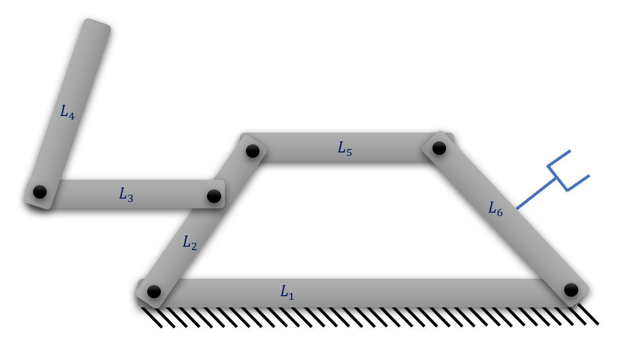
The mechanism should not have open-chains that do not have a connection from the base-link to the end-effector link.
In figure 1, the mechanism has the open-chain of links 5 and 6 that do not have a connection from the base-link to the end-effector link. Such mechanisms are removed.
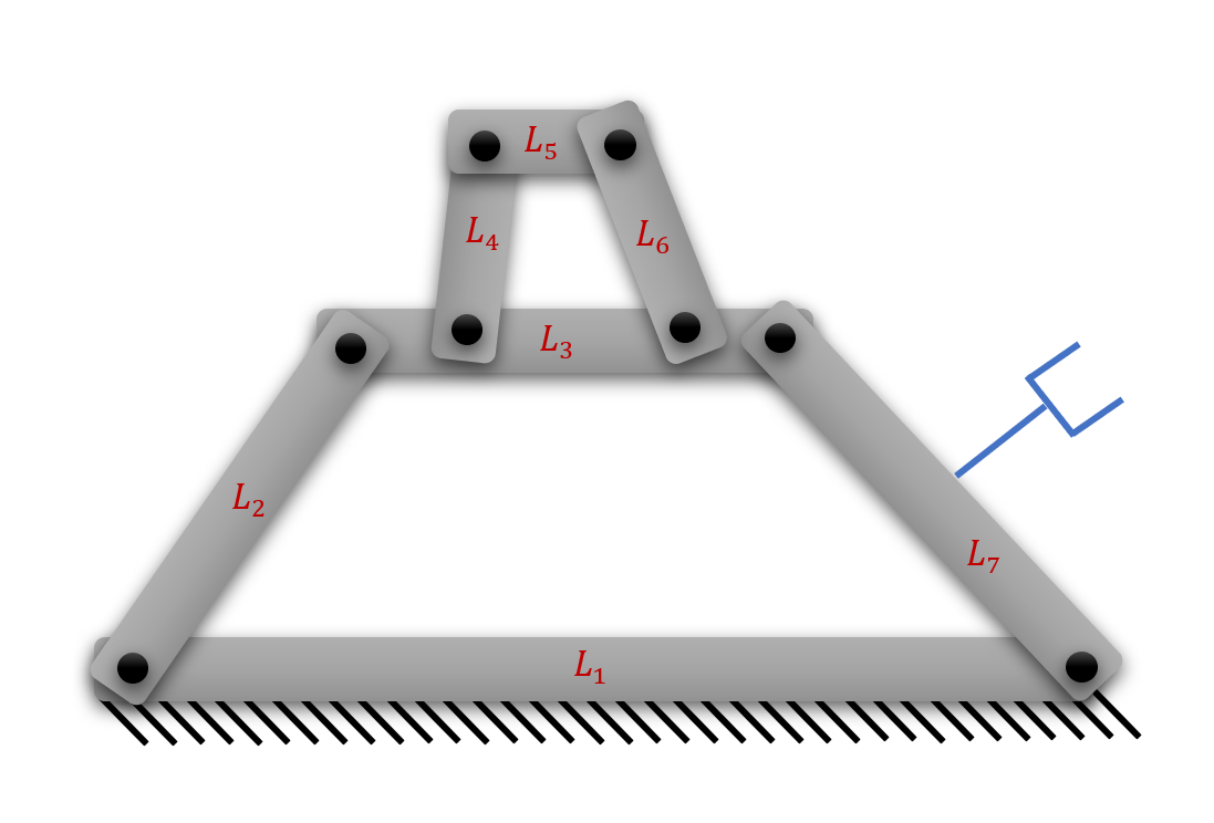
The mechanism should not have non-contributing loops.
In figure 2, the mechanism has the loop non-contributing and therefore cannot contribute, either actively or passively, to the transmission of velocity to the end-effector. Hence such mechanisms are to be removed.
The mechanisms should not be isomorphic.
Since two isomorphic adjacency matrices represent the same mechanism, one of them needs to be removed. In this study, the first link represents the base link, and the last link represents the end-effector link. Therefore, isomorphism in this context is defined to be the mechanism-repetition for a unique set of base and end-effector links.
The end-effector should not have a connection with only two spherical joints.
If the end-effector of a manipulator is connected to the rest of the mechanism through two spherical joints and no other joint, in which case the end-effector is connected to one link with a spherical joint and to another link with the other spherical joint, then the relative velocity of the end-effector about the axis passing through the two spherical joints, cannot be controlled by the actuators. Hence, such mechanisms are to be removed.
The actuation should not be locked within a sub-mechanism of the main mechanism.
If an actuator-joint gets permanently locked within a sub-mechanism of the main mechanism for all its configurations by virtue of the kinds of joints connected to the links, then the actuation cannot be feasible from that joint. Hence, if a mechanism has the sum of non-locked revolute and non-locked prismatic joints less than the required DOF, then such matrices are removed.
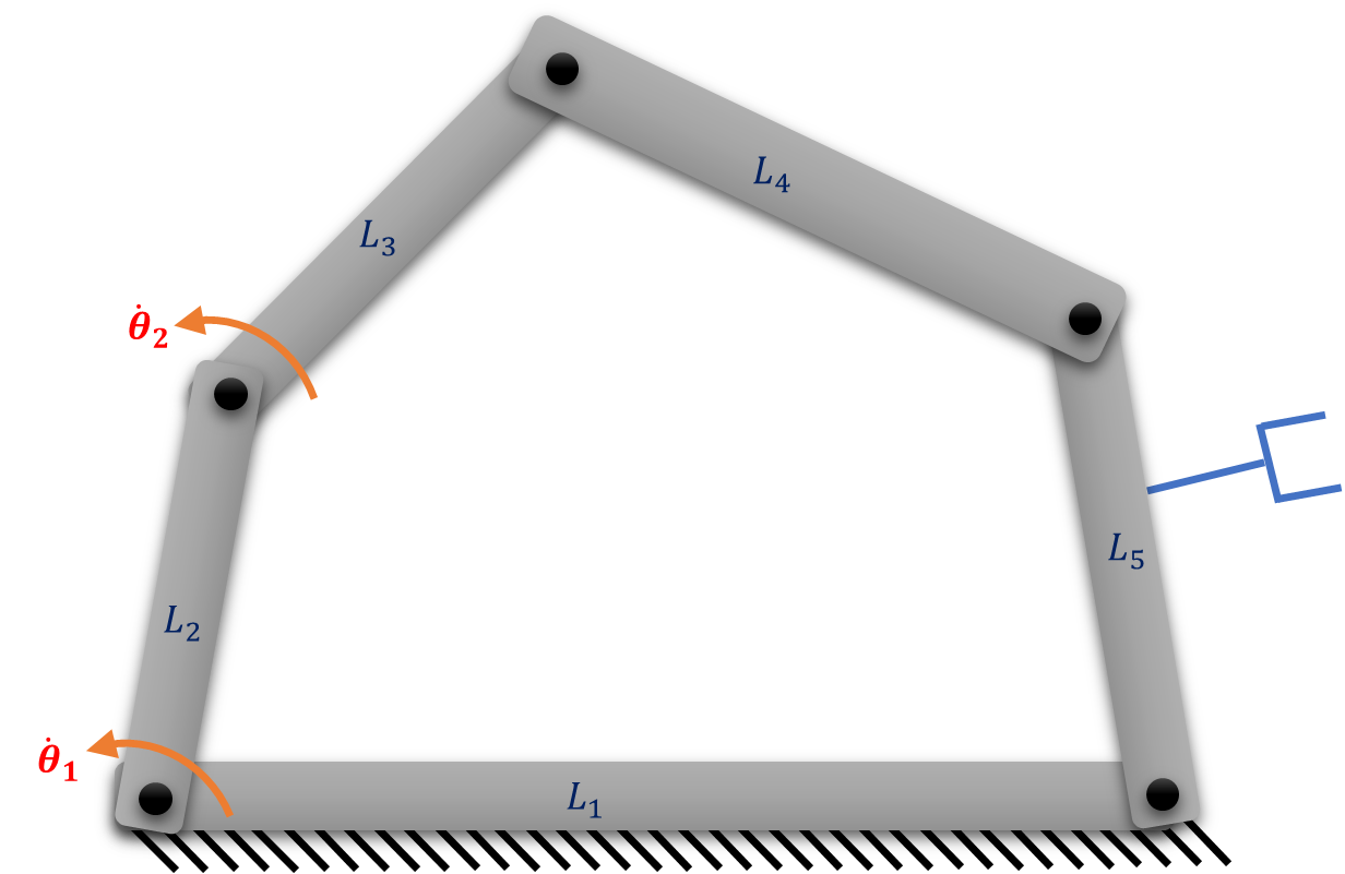
The number of independent directions of the final velocity of the end-effector should be equal to the number of independent actuations.
In figure 3, assuming all the links are connected with revolute pairs, even if both the actuating velocities and are independently provided, the end-effector can have only one independent component of velocity, and hence such manipulators are to be removed.
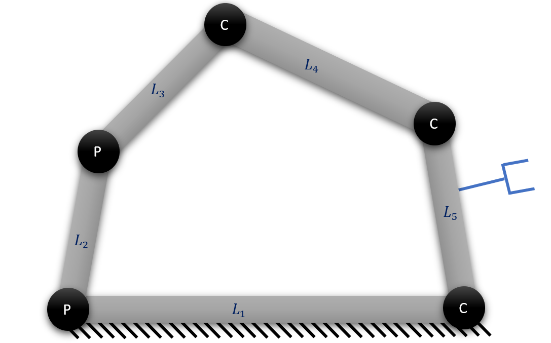
The number of arbitrarily positioned and oriented joints that contribute independent angular motions in a loop should be more than 3 for the motion to be possible in any of the joints.
In the figure 4, the loop has only three joints that can facilitate relative angular motions between the links connected to them, namely the cylindrical joint connecting , the cylindrical joint connecting and the cylindrical joint connecting . Thus, in order for the joints to facilitate angular motion, the resultant angular velocity produced by the joint connecting and the joint connecting should be about the same axis as the joint connecting , which is a restricted case. Assuming that the positions and the orientations of the joints are arbitrary, none of the cylindrical joints would produce angular motion but can produce only linear motion and therefore all the rotations of the cylindrical joints would be locked. Hence, at least four independent angular motions are needed for arbitrarily located and oriented joints to accommodate angular motion in a loop.
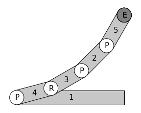
The mechanism should not have parts of it uncontrollable by the actuators except as superfluous DOF mechanisms
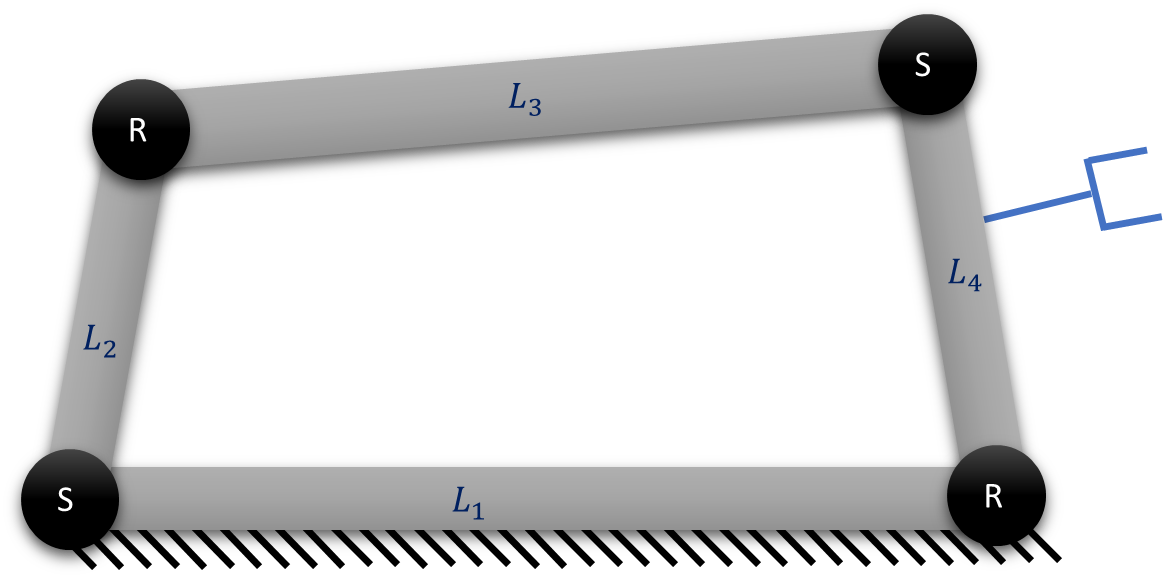
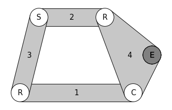
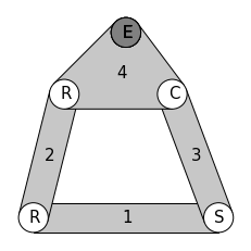
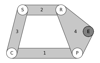
If the manipulator has any two of its complementary parts connected by two spherical joints and no other joint, and if the base link lies on one part whilst the end-effector link lies on the other part, then the rotation of the end-effector link along the axis passing through centres of the two spherical joints cannot be controlled by the actuators. An example of it is the manipulator shown by the schematic diagram in 5, in which the rotation of the part consisting of links 3 and 4 cannot be controlled by the actuator along the axis passing through the centres of two spherical joints. Hence, such mechanisms are to be removed. Furthermore, if both the base link and the end-effector link lie on the same part and if the other part comprises more than one link, the manipulator cannot control the rotation of that part about the axis passing through the centres of the two spherical joints by the actuators. An example of such a case is shown in 6, where the angular velocity of the part of manipulator consisting of links 2 and 3 about the axis passing through the centres of the two spherical joints, cannot be controlled by the actuator of the manipulator. Hence, such mechanisms are also removed. Even though the latter case does not affect the velocity of the end-effector, such manipulators are removed with the convention that any moving parts of mechanism that cannot be controlled by the actuators are removed except if the uncontrollable part of mechanism consists of just one link. The inclusion of such manipulators is suggested as future scope.
If all the velocities of the end-effector are of purely linear motion then the DOF of the manipulator cannot exceed 3
If all the joints in the manipulator are prismatic then the end-effector cannot have angular motion but can only have linear motion. Since the 3D space allows only three independent linear components and three angular components of velocity of the end-effector, the DOF that can be attained by mere linear motion can at most be 3, as any additional linear actuation would cause a motion that is within the three linear components of the end-effector’s velocity. Hence, if a manipulator has only prismatic type of joints but has its DOF more than 3, then such manipulator is omitted.

3 Results
3.1 Enumeration of manipulators of DOF 1
To reduce the complexity, four-link manipulators of 1DOF are enumerated.
| Class | Type | Count |
|---|---|---|
| Class 1 | ||
| Class 2 | ||
| Class 3 | ||
| Class 4 | ||
| Class 5 | ||
| Class 6 | ||
| Class 7 | ||
| Class 8 | ||
| Total | 96 |
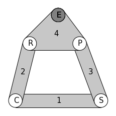
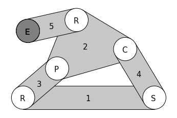
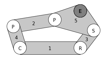
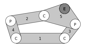
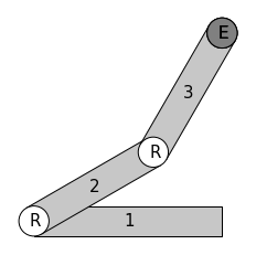
After permuting the off-diagonal elements of adjacency matrix with all possible values and eliminating invalid and isomorphic adjacency matrices, 96 distinct adjacency matrices are finally obtained. Based on the sets of joints involved, the enumerated manipulators are classified into 8 classes. The description of each class along with the count of manipulators is shown in table 1. Schematic representations of manipulators of all the 8 classes are shown below, in which the first link is the base link and the dark circle inscribed with ‘E’ represents the end-effector point.
 |
| 1D-M1 |
 |
| 1D-M2 |
 |
| 1D-M3 |
 |
| 1D-M4 |
 |
| 1D-M5 |
 |
| 1D-M6 |
 |
| 1D-M7 |
 |
| 1D-M8 |
 |
| 1D-M9 |
 |
| 1D-M10 |
 |
| 1D-M11 |
 |
| 1D-M12 |
 |
| 1D-M13 |
 |
| 1D-M14 |
 |
| 1D-M15 |
 |
| 1D-M16 |
 |
| 1D-M17 |
 |
| 1D-M18 |
 |
| 1D-M19 |
 |
| 1D-M20 |
 |
| 1D-M21 |
 |
| 1D-M22 |
 |
| 1D-M23 |
 |
| 1D-M24 |
 |
| 1D-M25 |
 |
| 1D-M26 |
 |
| 1D-M27 |
 |
| 1D-M28 |
 |
| 1D-M29 |
 |
| 1D-M30 |
 |
| 1D-M31 |
 |
| 1D-M32 |
 |
| 1D-M33 |
 |
| 1D-M34 |
 |
| 1D-M35 |
 |
| 1D-M36 |
 |
| 1D-M37 |
 |
| 1D-M38 |
 |
| 1D-M39 |
 |
| 1D-M40 |
 |
| 1D-M41 |
 |
| 1D-M42 |
 |
| 1D-M43 |
 |
| 1D-M44 |
 |
| 1D-M45 |
 |
| 1D-M46 |
 |
| 1D-M47 |
 |
| 1D-M48 |
 |
| 1D-M49 |
 |
| 1D-M50 |
 |
| 1D-M51 |
 |
| 1D-M52 |
 |
| 1D-M53 |
 |
| 1D-M54 |
 |
| 1D-M55 |
 |
| 1D-M56 |
 |
| 1D-M57 |
 |
| 1D-M58 |
 |
| 1D-M59 |
 |
| 1D-M60 |
 |
| 1D-M61 |
 |
| 1D-M62 |
 |
| 1D-M63 |
 |
| 1D-M64 |
 |
| 1D-M65 |
 |
| 1D-M66 |
 |
| 1D-M67 |
 |
| 1D-M68 |
 |
| 1D-M69 |
 |
| 1D-M70 |
 |
| 1D-M71 |
 |
| 1D-M72 |
 |
| 1D-M73 |
 |
| 1D-M74 |
 |
| 1D-M75 |
 |
| 1D-M76 |
 |
| 1D-M77 |
 |
| 1D-M78 |
 |
| 1D-M79 |
 |
| 1D-M80 |
 |
| 1D-M81 |
 |
| 1D-M82 |
 |
| 1D-M83 |
 |
| 1D-M84 |
 |
| 1D-M85 |
 |
| 1D-M86 |
 |
| 1D-M87 |
 |
| 1D-M88 |
 |
| 1D-M89 |
 |
| 1D-M90 |
 |
| 1D-M91 |
 |
| 1D-M92 |
 |
| 1D-M93 |
 |
| 1D-M94 |
 |
| 1D-M95 |
 |
| 1D-M96 |
3.2 Enumeration of manipulators of DOF 2
Enumeration of 2-DOF manipulators is done from the list of three-link, four-link and five-link manipulators.
| Class | Type | Count |
|---|---|---|
| Class 1 | ||
| Class 2 | ||
| Class 3 | ||
| Class 4 | ||
| Class 5 | ||
| Class 6 | ||
| Class 7 | ||
| Class 8 | ||
| Class 9 | ||
| Class 10 | ||
| Class 11 | ||
| Class 12 | ||
| Class 13 | ||
| Class 14 | ||
| Total | 645 |
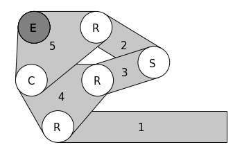
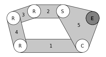
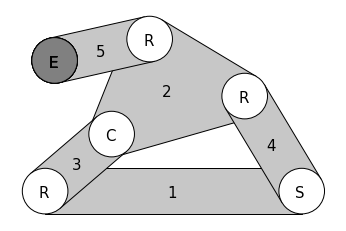
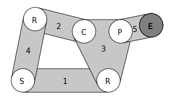
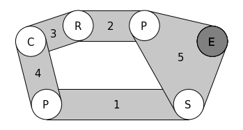
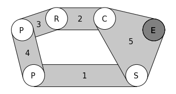
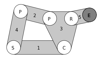
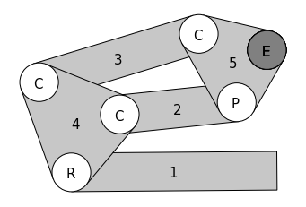
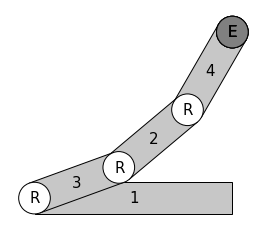
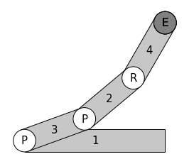
After permuting the off-diagonal elements of adjacency matrix with all possible values and eliminating invalid and isomorphic adjacency matrices, 645 distinct adjacency matrices are finally obtained. Based on the sets of joints involved, the enumerated manipulators are classified into 14 classes. The description of each class along with the count of manipulators is shown in table 2. Schematic representations of manipulators of all the 14 classes are shown below, in which the first link is the base link and the dark circle inscribed with ‘E’ represents the end-effector point.
 |
| 2D-M1 |
 |
| 2D-M2 |
 |
| 2D-M3 |
 |
| 2D-M4 |
 |
| 2D-M5 |
 |
| 2D-M6 |
 |
| 2D-M7 |
 |
| 2D-M8 |
 |
| 2D-M9 |
 |
| 2D-M10 |
 |
| 2D-M11 |
 |
| 2D-M12 |
 |
| 2D-M13 |
 |
| 2D-M14 |
 |
| 2D-M15 |
 |
| 2D-M16 |
 |
| 2D-M17 |
 |
| 2D-M18 |
 |
| 2D-M19 |
 |
| 2D-M20 |
 |
| 2D-M21 |
 |
| 2D-M22 |
 |
| 2D-M23 |
 |
| 2D-M24 |
 |
| 2D-M25 |
 |
| 2D-M26 |
 |
| 2D-M27 |
 |
| 2D-M28 |
 |
| 2D-M29 |
 |
| 2D-M30 |
 |
| 2D-M31 |
 |
| 2D-M32 |
 |
| 2D-M33 |
 |
| 2D-M34 |
 |
| 2D-M35 |
 |
| 2D-M36 |
 |
| 2D-M37 |
 |
| 2D-M38 |
 |
| 2D-M39 |
 |
| 2D-M40 |
 |
| 2D-M41 |
 |
| 2D-M42 |
 |
| 2D-M43 |
 |
| 2D-M44 |
 |
| 2D-M45 |
 |
| 2D-M46 |
 |
| 2D-M47 |
 |
| 2D-M48 |
 |
| 2D-M49 |
 |
| 2D-M50 |
 |
| 2D-M51 |
 |
| 2D-M52 |
 |
| 2D-M53 |
 |
| 2D-M54 |
 |
| 2D-M55 |
 |
| 2D-M56 |
 |
| 2D-M57 |
 |
| 2D-M58 |
 |
| 2D-M59 |
 |
| 2D-M60 |
 |
| 2D-M61 |
 |
| 2D-M62 |
 |
| 2D-M63 |
 |
| 2D-M64 |
 |
| 2D-M65 |
 |
| 2D-M66 |
 |
| 2D-M67 |
 |
| 2D-M68 |
 |
| 2D-M69 |
 |
| 2D-M70 |
 |
| 2D-M71 |
 |
| 2D-M72 |
 |
| 2D-M73 |
 |
| 2D-M74 |
 |
| 2D-M75 |
 |
| 2D-M76 |
 |
| 2D-M77 |
 |
| 2D-M78 |
 |
| 2D-M79 |
 |
| 2D-M80 |
 |
| 2D-M81 |
 |
| 2D-M82 |
 |
| 2D-M83 |
 |
| 2D-M84 |
 |
| 2D-M85 |
 |
| 2D-M86 |
 |
| 2D-M87 |
 |
| 2D-M88 |
 |
| 2D-M89 |
 |
| 2D-M90 |
 |
| 2D-M91 |
 |
| 2D-M92 |
 |
| 2D-M93 |
 |
| 2D-M94 |
 |
| 2D-M95 |
 |
| 2D-M96 |
 |
| 2D-M97 |
 |
| 2D-M98 |
 |
| 2D-M99 |
 |
| 2D-M100 |
 |
| 2D-M101 |
 |
| 2D-M102 |
 |
| 2D-M103 |
 |
| 2D-M104 |
 |
| 2D-M105 |
 |
| 2D-M106 |
 |
| 2D-M107 |
 |
| 2D-M108 |
 |
| 2D-M109 |
 |
| 2D-M110 |
 |
| 2D-M111 |
 |
| 2D-M112 |
 |
| 2D-M113 |
 |
| 2D-M114 |
 |
| 2D-M115 |
 |
| 2D-M116 |
 |
| 2D-M117 |
 |
| 2D-M118 |
 |
| 2D-M119 |
 |
| 2D-M120 |
 |
| 2D-M121 |
 |
| 2D-M122 |
 |
| 2D-M123 |
 |
| 2D-M124 |
 |
| 2D-M125 |
 |
| 2D-M126 |
 |
| 2D-M127 |
 |
| 2D-M128 |
 |
| 2D-M129 |
 |
| 2D-M130 |
 |
| 2D-M131 |
 |
| 2D-M132 |
 |
| 2D-M133 |
 |
| 2D-M134 |
 |
| 2D-M135 |
 |
| 2D-M136 |
 |
| 2D-M137 |
 |
| 2D-M138 |
 |
| 2D-M139 |
 |
| 2D-M140 |
 |
| 2D-M141 |
 |
| 2D-M142 |
 |
| 2D-M143 |
 |
| 2D-M144 |
 |
| 2D-M145 |
 |
| 2D-M146 |
 |
| 2D-M147 |
 |
| 2D-M148 |
 |
| 2D-M149 |
 |
| 2D-M150 |
 |
| 2D-M151 |
 |
| 2D-M152 |
 |
| 2D-M153 |
 |
| 2D-M154 |
 |
| 2D-M155 |
 |
| 2D-M156 |
 |
| 2D-M157 |
 |
| 2D-M158 |
 |
| 2D-M159 |
 |
| 2D-M160 |
 |
| 2D-M161 |
 |
| 2D-M162 |
 |
| 2D-M163 |
 |
| 2D-M164 |
 |
| 2D-M165 |
 |
| 2D-M166 |
 |
| 2D-M167 |
 |
| 2D-M168 |
 |
| 2D-M169 |
 |
| 2D-M170 |
 |
| 2D-M171 |
 |
| 2D-M172 |
 |
| 2D-M173 |
 |
| 2D-M174 |
 |
| 2D-M175 |
 |
| 2D-M176 |
 |
| 2D-M177 |
 |
| 2D-M178 |
 |
| 2D-M179 |
 |
| 2D-M180 |
 |
| 2D-M181 |
 |
| 2D-M182 |
 |
| 2D-M183 |
 |
| 2D-M184 |
 |
| 2D-M185 |
 |
| 2D-M186 |
 |
| 2D-M187 |
 |
| 2D-M188 |
 |
| 2D-M189 |
 |
| 2D-M190 |
 |
| 2D-M191 |
 |
| 2D-M192 |
 |
| 2D-M193 |
 |
| 2D-M194 |
 |
| 2D-M195 |
 |
| 2D-M196 |
 |
| 2D-M197 |
 |
| 2D-M198 |
 |
| 2D-M199 |
 |
| 2D-M200 |
 |
| 2D-M201 |
 |
| 2D-M202 |
 |
| 2D-M203 |
 |
| 2D-M204 |
 |
| 2D-M205 |
 |
| 2D-M206 |
 |
| 2D-M207 |
 |
| 2D-M208 |
 |
| 2D-M209 |
 |
| 2D-M210 |
 |
| 2D-M211 |
 |
| 2D-M212 |
 |
| 2D-M213 |
 |
| 2D-M214 |
 |
| 2D-M215 |
 |
| 2D-M216 |
 |
| 2D-M217 |
 |
| 2D-M218 |
 |
| 2D-M219 |
 |
| 2D-M220 |
 |
| 2D-M221 |
 |
| 2D-M222 |
 |
| 2D-M223 |
 |
| 2D-M224 |
 |
| 2D-M225 |
 |
| 2D-M226 |
 |
| 2D-M227 |
 |
| 2D-M228 |
 |
| 2D-M229 |
 |
| 2D-M230 |
 |
| 2D-M231 |
 |
| 2D-M232 |
 |
| 2D-M233 |
 |
| 2D-M234 |
 |
| 2D-M235 |
 |
| 2D-M236 |
 |
| 2D-M237 |
 |
| 2D-M238 |
 |
| 2D-M239 |
 |
| 2D-M240 |
 |
| 2D-M241 |
 |
| 2D-M242 |
 |
| 2D-M243 |
 |
| 2D-M244 |
 |
| 2D-M245 |
 |
| 2D-M246 |
 |
| 2D-M247 |
 |
| 2D-M248 |
 |
| 2D-M249 |
 |
| 2D-M250 |
 |
| 2D-M251 |
 |
| 2D-M252 |
 |
| 2D-M253 |
 |
| 2D-M254 |
 |
| 2D-M255 |
 |
| 2D-M256 |
 |
| 2D-M257 |
 |
| 2D-M258 |
 |
| 2D-M259 |
 |
| 2D-M260 |
 |
| 2D-M261 |
 |
| 2D-M262 |
 |
| 2D-M263 |
 |
| 2D-M264 |
 |
| 2D-M265 |
 |
| 2D-M266 |
 |
| 2D-M267 |
 |
| 2D-M268 |
 |
| 2D-M269 |
 |
| 2D-M270 |
 |
| 2D-M271 |
 |
| 2D-M272 |
 |
| 2D-M273 |
 |
| 2D-M274 |
 |
| 2D-M275 |
 |
| 2D-M276 |
 |
| 2D-M277 |
 |
| 2D-M278 |
 |
| 2D-M279 |
 |
| 2D-M280 |
 |
| 2D-M281 |
 |
| 2D-M282 |
 |
| 2D-M283 |
 |
| 2D-M284 |
 |
| 2D-M285 |
 |
| 2D-M286 |
 |
| 2D-M287 |
 |
| 2D-M288 |
 |
| 2D-M289 |
 |
| 2D-M290 |
 |
| 2D-M291 |
 |
| 2D-M292 |
 |
| 2D-M293 |
 |
| 2D-M294 |
 |
| 2D-M295 |
 |
| 2D-M296 |
 |
| 2D-M297 |
 |
| 2D-M298 |
 |
| 2D-M299 |
 |
| 2D-M300 |
 |
| 2D-M301 |
 |
| 2D-M302 |
 |
| 2D-M303 |
 |
| 2D-M304 |
 |
| 2D-M305 |
 |
| 2D-M306 |
 |
| 2D-M307 |
 |
| 2D-M308 |
 |
| 2D-M309 |
 |
| 2D-M310 |
 |
| 2D-M311 |
 |
| 2D-M312 |
 |
| 2D-M313 |
 |
| 2D-M314 |
 |
| 2D-M315 |
 |
| 2D-M316 |
 |
| 2D-M317 |
 |
| 2D-M318 |
 |
| 2D-M319 |
 |
| 2D-M320 |
 |
| 2D-M321 |
 |
| 2D-M322 |
 |
| 2D-M323 |
 |
| 2D-M324 |
 |
| 2D-M325 |
 |
| 2D-M326 |
 |
| 2D-M327 |
 |
| 2D-M328 |
 |
| 2D-M329 |
 |
| 2D-M330 |
 |
| 2D-M331 |
 |
| 2D-M332 |
 |
| 2D-M333 |
 |
| 2D-M334 |
 |
| 2D-M335 |
 |
| 2D-M336 |
 |
| 2D-M337 |
 |
| 2D-M338 |
 |
| 2D-M339 |
 |
| 2D-M340 |
 |
| 2D-M341 |
 |
| 2D-M342 |
 |
| 2D-M343 |
 |
| 2D-M344 |
 |
| 2D-M345 |
 |
| 2D-M346 |
 |
| 2D-M347 |
 |
| 2D-M348 |
 |
| 2D-M349 |
 |
| 2D-M350 |
 |
| 2D-M351 |
 |
| 2D-M352 |
 |
| 2D-M353 |
 |
| 2D-M354 |
 |
| 2D-M355 |
 |
| 2D-M356 |
 |
| 2D-M357 |
 |
| 2D-M358 |
 |
| 2D-M359 |
 |
| 2D-M360 |
 |
| 2D-M361 |
 |
| 2D-M362 |
 |
| 2D-M363 |
 |
| 2D-M364 |
 |
| 2D-M365 |
 |
| 2D-M366 |
 |
| 2D-M367 |
 |
| 2D-M368 |
 |
| 2D-M369 |
 |
| 2D-M370 |
 |
| 2D-M371 |
 |
| 2D-M372 |
 |
| 2D-M373 |
 |
| 2D-M374 |
 |
| 2D-M375 |
 |
| 2D-M376 |
 |
| 2D-M377 |
 |
| 2D-M378 |
 |
| 2D-M379 |
 |
| 2D-M380 |
 |
| 2D-M381 |
 |
| 2D-M382 |
 |
| 2D-M383 |
 |
| 2D-M384 |
 |
| 2D-M385 |
 |
| 2D-M386 |
 |
| 2D-M387 |
 |
| 2D-M388 |
 |
| 2D-M389 |
 |
| 2D-M390 |
 |
| 2D-M391 |
 |
| 2D-M392 |
 |
| 2D-M393 |
 |
| 2D-M394 |
 |
| 2D-M395 |
 |
| 2D-M396 |
 |
| 2D-M397 |
 |
| 2D-M398 |
 |
| 2D-M399 |
 |
| 2D-M400 |
 |
| 2D-M401 |
 |
| 2D-M402 |
 |
| 2D-M403 |
 |
| 2D-M404 |
 |
| 2D-M405 |
 |
| 2D-M406 |
 |
| 2D-M407 |
 |
| 2D-M408 |
 |
| 2D-M409 |
 |
| 2D-M410 |
 |
| 2D-M411 |
 |
| 2D-M412 |
 |
| 2D-M413 |
 |
| 2D-M414 |
 |
| 2D-M415 |
 |
| 2D-M416 |
 |
| 2D-M417 |
 |
| 2D-M418 |
 |
| 2D-M419 |
 |
| 2D-M420 |
 |
| 2D-M421 |
 |
| 2D-M422 |
 |
| 2D-M423 |
 |
| 2D-M424 |
 |
| 2D-M425 |
 |
| 2D-M426 |
 |
| 2D-M427 |
 |
| 2D-M428 |
 |
| 2D-M429 |
 |
| 2D-M430 |
 |
| 2D-M431 |
 |
| 2D-M432 |
 |
| 2D-M433 |
 |
| 2D-M434 |
 |
| 2D-M435 |
 |
| 2D-M436 |
 |
| 2D-M437 |
 |
| 2D-M438 |
 |
| 2D-M439 |
 |
| 2D-M440 |
 |
| 2D-M441 |
 |
| 2D-M442 |
 |
| 2D-M443 |
 |
| 2D-M444 |
 |
| 2D-M445 |
 |
| 2D-M446 |
 |
| 2D-M447 |
 |
| 2D-M448 |
 |
| 2D-M449 |
 |
| 2D-M450 |
 |
| 2D-M451 |
 |
| 2D-M452 |
 |
| 2D-M453 |
 |
| 2D-M454 |
 |
| 2D-M455 |
 |
| 2D-M456 |
 |
| 2D-M457 |
 |
| 2D-M458 |
 |
| 2D-M459 |
 |
| 2D-M460 |
 |
| 2D-M461 |
 |
| 2D-M462 |
 |
| 2D-M463 |
 |
| 2D-M464 |
 |
| 2D-M465 |
 |
| 2D-M466 |
 |
| 2D-M467 |
 |
| 2D-M468 |
 |
| 2D-M469 |
 |
| 2D-M470 |
 |
| 2D-M471 |
 |
| 2D-M472 |
 |
| 2D-M473 |
 |
| 2D-M474 |
 |
| 2D-M475 |
 |
| 2D-M476 |
 |
| 2D-M477 |
 |
| 2D-M478 |
 |
| 2D-M479 |
 |
| 2D-M480 |
 |
| 2D-M481 |
 |
| 2D-M482 |
 |
| 2D-M483 |
 |
| 2D-M484 |
 |
| 2D-M485 |
 |
| 2D-M486 |
 |
| 2D-M487 |
 |
| 2D-M488 |
 |
| 2D-M489 |
 |
| 2D-M490 |
 |
| 2D-M491 |
 |
| 2D-M492 |
 |
| 2D-M493 |
 |
| 2D-M494 |
 |
| 2D-M495 |
 |
| 2D-M496 |
 |
| 2D-M497 |
 |
| 2D-M498 |
 |
| 2D-M499 |
 |
| 2D-M500 |
 |
| 2D-M501 |
 |
| 2D-M502 |
 |
| 2D-M503 |
 |
| 2D-M504 |
 |
| 2D-M505 |
 |
| 2D-M506 |
 |
| 2D-M507 |
 |
| 2D-M508 |
 |
| 2D-M509 |
 |
| 2D-M510 |
 |
| 2D-M511 |
 |
| 2D-M512 |
 |
| 2D-M513 |
 |
| 2D-M514 |
 |
| 2D-M515 |
 |
| 2D-M516 |
 |
| 2D-M517 |
 |
| 2D-M518 |
 |
| 2D-M519 |
 |
| 2D-M520 |
 |
| 2D-M521 |
 |
| 2D-M522 |
 |
| 2D-M523 |
 |
| 2D-M524 |
 |
| 2D-M525 |
 |
| 2D-M526 |
 |
| 2D-M527 |
 |
| 2D-M528 |
 |
| 2D-M529 |
 |
| 2D-M530 |
 |
| 2D-M531 |
 |
| 2D-M532 |
 |
| 2D-M533 |
 |
| 2D-M534 |
 |
| 2D-M535 |
 |
| 2D-M536 |
 |
| 2D-M537 |
 |
| 2D-M538 |
 |
| 2D-M539 |
 |
| 2D-M540 |
 |
| 2D-M541 |
 |
| 2D-M542 |
 |
| 2D-M543 |
 |
| 2D-M544 |
 |
| 2D-M545 |
 |
| 2D-M546 |
 |
| 2D-M547 |
 |
| 2D-M548 |
 |
| 2D-M549 |
 |
| 2D-M550 |
 |
| 2D-M551 |
 |
| 2D-M552 |
 |
| 2D-M553 |
 |
| 2D-M554 |
 |
| 2D-M555 |
 |
| 2D-M556 |
 |
| 2D-M557 |
 |
| 2D-M558 |
 |
| 2D-M559 |
 |
| 2D-M560 |
 |
| 2D-M561 |
 |
| 2D-M562 |
 |
| 2D-M563 |
 |
| 2D-M564 |
 |
| 2D-M565 |
 |
| 2D-M566 |
 |
| 2D-M567 |
 |
| 2D-M568 |
 |
| 2D-M569 |
 |
| 2D-M570 |
 |
| 2D-M571 |
 |
| 2D-M572 |
 |
| 2D-M573 |
 |
| 2D-M574 |
 |
| 2D-M575 |
 |
| 2D-M576 |
 |
| 2D-M577 |
 |
| 2D-M578 |
 |
| 2D-M579 |
 |
| 2D-M580 |
 |
| 2D-M581 |
 |
| 2D-M582 |
 |
| 2D-M583 |
 |
| 2D-M584 |
 |
| 2D-M585 |
 |
| 2D-M586 |
 |
| 2D-M587 |
 |
| 2D-M588 |
 |
| 2D-M589 |
 |
| 2D-M590 |
 |
| 2D-M591 |
 |
| 2D-M592 |
 |
| 2D-M593 |
 |
| 2D-M594 |
 |
| 2D-M595 |
 |
| 2D-M596 |
 |
| 2D-M597 |
 |
| 2D-M598 |
 |
| 2D-M599 |
 |
| 2D-M600 |
 |
| 2D-M601 |
 |
| 2D-M602 |
 |
| 2D-M603 |
 |
| 2D-M604 |
 |
| 2D-M605 |
 |
| 2D-M606 |
 |
| 2D-M607 |
 |
| 2D-M608 |
 |
| 2D-M609 |
 |
| 2D-M610 |
 |
| 2D-M611 |
 |
| 2D-M612 |
 |
| 2D-M613 |
 |
| 2D-M614 |
 |
| 2D-M615 |
 |
| 2D-M616 |
 |
| 2D-M617 |
 |
| 2D-M618 |
 |
| 2D-M619 |
 |
| 2D-M620 |
 |
| 2D-M621 |
 |
| 2D-M622 |
 |
| 2D-M623 |
 |
| 2D-M624 |
 |
| 2D-M625 |
 |
| 2D-M626 |
 |
| 2D-M627 |
 |
| 2D-M628 |
 |
| 2D-M629 |
 |
| 2D-M630 |
 |
| 2D-M631 |
 |
| 2D-M632 |
 |
| 2D-M633 |
 |
| 2D-M634 |
 |
| 2D-M635 |
 |
| 2D-M636 |
 |
| 2D-M637 |
 |
| 2D-M638 |
 |
| 2D-M639 |
 |
| 2D-M640 |
 |
| 2D-M641 |
 |
| 2D-M642 |
 |
| 2D-M643 |
 |
| 2D-M644 |
 |
| 2D-M645 |
3.3 Enumeration of manipulators of DOF 3
Enumeration of 3-DOF manipulators is done from the list of three-link, four-link and five-link manipulators.
| Class | Type | Count |
|---|---|---|
| Class 1 | ||
| Class 2 | ||
| Class 3 | ||
| Class 4 | ||
| Total | 8 |
After permuting the off-diagonal elements of adjacency matrix with all possible values and eliminating invalid and isomorphic adjacency matrices, 8 distinct adjacency matrices are finally obtained. Based on the sets of joints involved, the enumerated manipulators are classified into 4 classes. The description of each class along with the count of manipulators is shown in table 3. Schematic representations of manipulators of all the 4 classes are shown below, in which the first link is the base link and the dark circle inscribed with ‘E’ represents the end-effector point.
 |
| 3D-M1 |
 |
| 3D-M2 |
 |
| 3D-M3 |
 |
| 3D-M4 |
 |
| 3D-M5 |
 |
| 3D-M6 |
 |
| 3D-M7 |
 |
| 3D-M8 |
3.4 Enumeration of manipulators of DOF 4
Enumeration of 4-DOF manipulators is done from the list of three-link, four-link and five-link manipulators.
| Class | Type | Count |
|---|---|---|
| Class 1 | ||
| Class 2 | ||
| Class 3 | ||
| Class 4 | ||
| Total | 15 |
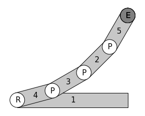
After permuting the off-diagonal elements of adjacency matrix with all possible values and eliminating invalid and isomorphic adjacency matrices, 8 distinct adjacency matrices are finally obtained. Based on the sets of joints involved, the enumerated manipulators are classified into 4 classes. The description of each class along with the count of manipulators is shown in table 4. Schematic representations of manipulators of all the 4 classes are shown below, in which the first link is the base link and the dark circle inscribed with ‘E’ represents the end-effector point.
 |
| 4D-M1 |
 |
| 4D-M2 |
 |
| 4D-M3 |
 |
| 4D-M4 |
 |
| 4D-M5 |
 |
| 4D-M6 |
 |
| 4D-M7 |
 |
| 4D-M8 |
 |
| 4D-M9 |
 |
| 4D-M10 |
 |
| 4D-M11 |
 |
| 4D-M12 |
 |
| 4D-M13 |
 |
| 4D-M14 |
 |
| 4D-M15 |
4 Limitations
The criterion used for calculating DOF in this study is limited to Kutzbach criterion. But there are some valid mechanisms that are classified as structures by Kutzbach criterion. An example of this is four-bar PPPP spatial mechanism. And the reason for this is that since all the motion allowed/facilitated by any serial/parallel combination of prismatic joints is only linear but not angular, the Jacobian has non-zero elements only for half of its rows (the upper three rows), and any three linearly independent columns of Jacobian would reach the threshold of a structure and any fourth column would enable reciprocation with the set of other three joints, thereby making the motion possible. On the other hand, if there were other kinds of joints existing in the closed-loop mechanism that facilitate rotary motion as well, then all the six rows of Jacobian could be non-zero, and hence six linearly independent columns of Jacobian would reach the threshold of a structure this time, requiring a 7th column to enable reciprocation with those six linearly independent columns in order to make motion possible in a general case. This is the reason why four-bar RRRR spatial kinematic chain does not move whilst four-bar PPPP spatial kinematic chain does, and 7-bar RRRRRRR mechanism is the minimum analogous mechanism that allows motion. But since Kutzbach criterion does not distinguish prismatic joint from revolute joint but considers them to be equivalently contributing, this criterion is not sufficient to determine the exact DOF of mechanisms in some cases. And some of the criteria shown in sub-section 2.2 are developed by analysing the Jacobian of each manipulator after enumerating all the possible adjacency matrices, and hence there exist some manipulators in the enumerated list that do not satisfy the Kutzbach criterion yet have the required DOF. Hence the enumeration presented in this study is not complete. The completeness of enumeration is suggested as future scope.
5 Conclusion
The concept of adjacency matrix is used for enumeration of spatial manipulators with four types of joints, namely revolute, prismatic, cylindrical and spherical joints, by analysing its applicability to spatial manipulators. Criteria for eliminating invalid and isomorphic adjacency matrices are presented. Finally, 96 1-DOF manipulators of 8 classes are enumerated from 4-link adjacency matrices, 645 2-DOF manipulators of 14 classes, 8 3-DOF manipulators of 4 classes and 15 4-DOF manipulators of 4 classes are enumerated from 3-link, 4-link and 5-link adjacency matrices. The schematic diagrams of the manipulators are presented. This set of enumerated manipulators is used in the companion study [23] on dimensional synthesis wherein dimensions are presented for each manipulator for optimal performance in a particular context that is described in the companion paper. The two studies together aim to provide to the designer an atlas of manipulators along with their optimal dimensions and their ranking, which can be useful to the designer to choose the best manipulator relevant to the context mentioned in the companion paper.
Since the steps provided in this study seem to be sufficient for enumeration of spatial manipulators, this enumeration study is concluded with the presented manipulators to move on to the companion study of dimensional synthesis, although the enumeration study can be extended to higher number of links and with inclusion of more types of joints such as universal and helical joints. The authors suggest this as future scope.
References
- [1] Crossley, F. E. A contribution to gruebler’s theory in the number synthesis of plane mechanisms. \JournalTitleJournal of Engineering for Industry 86, 1–5 (1964).
- [2] Davies, T. H. & Crossley, F. E. Structural analysis of plane linkages by franke’s condensed notation. \JournalTitleJournal of Mechanisms 1, 171–183 (1966).
- [3] Vucina, D. & Freudenstein, F. An application of graph theory and nonlinear programming to the kinematic synthesis of mechanisms. \JournalTitleMechanism and machine theory 26, 553–563 (1991).
- [4] Manolescu, N. A method based on baranov trusses, and using graph theory to find the set of planar jointed kinematic chains and mechanisms. \JournalTitleMechanism and Machine Theory 8, 3–22 (1973).
- [5] Jinkui, C. & Weiqing, C. Systemics of assur groups with multiple joints. \JournalTitleMechanism and machine theory 33, 1127–1133 (1998).
- [6] Mruthyunjaya, T. Kinematic structure of mechanisms revisited. \JournalTitleMechanism and machine theory 38, 279–320 (2003).
- [7] Raicu, A. Matrices associated with kinematic chains with from 3 to 5 members. \JournalTitleMechanism and Machine theory 9, 123–129 (1974).
- [8] Mruthyunjaya, T. & Raghavan, M. Structural analysis of kinematic chains and mechanisms based on matrix representation. \JournalTitleJournal of Mechanical Design 101, 488–494 (1979).
- [9] Yang, W., Ding, H. & Kecskeméthy, A. Structural synthesis towards intelligent design of plane mechanisms: Current status and future research trend. \JournalTitleMechanism and Machine Theory 171, 104715 (2022).
- [10] Simoni, R., Carboni, A. & Martins, D. Enumeration of kinematic chains and mechanisms. \JournalTitleProceedings of the Institution of Mechanical Engineers, Part C: Journal of Mechanical Engineering Science 223, 1017–1024 (2009).
- [11] Huang, P. & Ding, H. Structural synthesis of baranov trusses with up to 13 links. \JournalTitleJournal of Mechanical Design 141 (2019).
- [12] Ding, H., Hou, F., Kecskeméthy, A. & Huang, Z. Synthesis of the whole family of planar 1-dof kinematic chains and creation of their atlas database. \JournalTitleMechanism and Machine Theory 47, 1–15 (2012).
- [13] Pucheta, M. & Cardona, A. An automated method for type synthesis of planar linkages based on a constrained subgraph isomorphism detection. \JournalTitleMultibody System Dynamics 18, 233–258 (2007).
- [14] Pozhbelko, V. & Ermoshina, E. Number structural synthesis and enumeration process of all possible sets of multiple joints for 1-dof up to 5-loop 12-link mechanisms on base of new mobility equation. \JournalTitleMechanism and Machine Theory 90, 108–127 (2015).
- [15] Li, S., Wang, H. & Dai, J. S. Assur-group inferred structural synthesis for planar mechanisms. \JournalTitleJournal of Mechanisms and Robotics 7, 041001 (2015).
- [16] Pierrot, F. & Company, O. H4: a new family of 4-dof parallel robots. In 1999 IEEE/ASME International Conference on Advanced Intelligent Mechatronics (Cat. No. 99TH8399), 508–513 (IEEE, 1999).
- [17] Zlatanov, D. & Gosselin, C. M. A family of new parallel architectures with four degrees of freedom. \JournalTitleElectronic Journal of Computational Kinematics 1, 1–10 (2001).
- [18] Fang, Y. & Tsai, L.-W. Structure synthesis of a class of 4-dof and 5-dof parallel manipulators with identical limb structures. \JournalTitleThe international journal of Robotics Research 21, 799–810 (2002).
- [19] Hess-Coelho, T. An alternative procedure for type synthesis of parallel mechanisms. In 12th IFTOMM World Congress, Besançon (Citeseer, 2007).
- [20] Long, S., Terakawa, T. & Komori, M. Type synthesis of 6-dof mobile parallel link mechanisms based on screw theory. \JournalTitleJournal of Advanced Mechanical Design, Systems, and Manufacturing 16, JAMDSM0005–JAMDSM0005 (2022).
- [21] Zeng, Q. & Fang, Y. Structural synthesis of serial-parallel hybrid mechanisms via group theory and representation of logical matrix. In 2009 International Conference on Information and Automation, 1392–1397, DOI: 10.1109/ICINFA.2009.5205134 (2009).
- [22] Zhang, K., Dai, J., Fang, Y. & Zeng, Q. String matrix based geometrical and topological representation of mechanisms. In The 13th World Congress in Mechanism and Machine Science, Guanajuato, México, 19–25 (Citeseer, 2011).
- [23] Jacob, A. S. & Dasgupta, B. Dimensional synthesis of spatial manipulators for velocity and force transmission for operation around a specified task point (N.A.). Unpublished.