Further author information: Send correspondence to Bryony Nickson: E-mail: bnickson@stsci.edu, Telephone: +1 410 338 6739
APLC-Optimization: an apodized pupil Lyot coronagraph design survey toolkit
Abstract
We present a publicly available software package developed for exploring apodized pupil Lyot coronagraph (APLC) solutions for various telescope architectures. In particular, the package optimizes the apodizer component of the APLC for a given focal-plane mask and Lyot stop geometry to meet a set of constraints (contrast, bandwidth etc.) on the coronagraph intensity in a given focal-plane region (i.e. dark zone). The package combines a high-contrast imaging simulation package (HCIPy[1]) with a third-party mathematical optimizer (Gurobi) to compute the linearly optimized binary mask that maximizes transmission. We provide examples of the application of this toolkit to several different telescope geometries, including the Gemini Planet Imager (GPI) and the High-contrast imager for Complex Aperture Telescopes (HiCAT) testbed. Finally, we summarize the results of a preliminary design survey for the case of a 6 m aperture off-axis space telescope, as recommended by the 2020 NASA Decadal Survey, exploring APLC solutions for different segment sizes. We then use the Pair-based Analytical model for Segmented Telescope Imaging from Space (PASTIS) to perform a segmented wavefront error tolerancing analysis on these solutions.
keywords:
coronagraph design, apodized pupil Lyot coronagraph, high-contrast imaging, LUVex, GOMaP, segmented telescopes1 INTRODUCTION
Direct imaging of exoplanets, including those which might be habitable, is a major goal in astronomy for the next decade. Indeed, this is one of the key recommendations of the 2018 National Academies of Sciences’ Exoplanet Science Strategy Report[2] and of the recent Astro2020 decadal survey: Pathways to Discovery in Astronomy and Astrophysics for the 2020s[3], which placed a “IR/O/UV telescope optimized for observing habitable exoplanets and general astrophysics” as their highest priority recommendation in the frontier category for space.
The complexity of directly imaging exoplanets stems from two main challenges: the need to resolve substellar companions at very small angular separations from their host stars, as well as the large flux ratio between the planet and star. For these reasons, we require large-aperture telescopes equipped with coronagraphic instruments capable of extreme starlight suppression. In this study we focus on a well tested coronagraph type that is currently the basis for several ground-based high-contrast imaging instruments, the Apodized Pupil Lyot Coronagraph (APLC) - a Lyot-style coronagraph that suppresses starlight through a series of amplitude operations on the on-axis electric field.
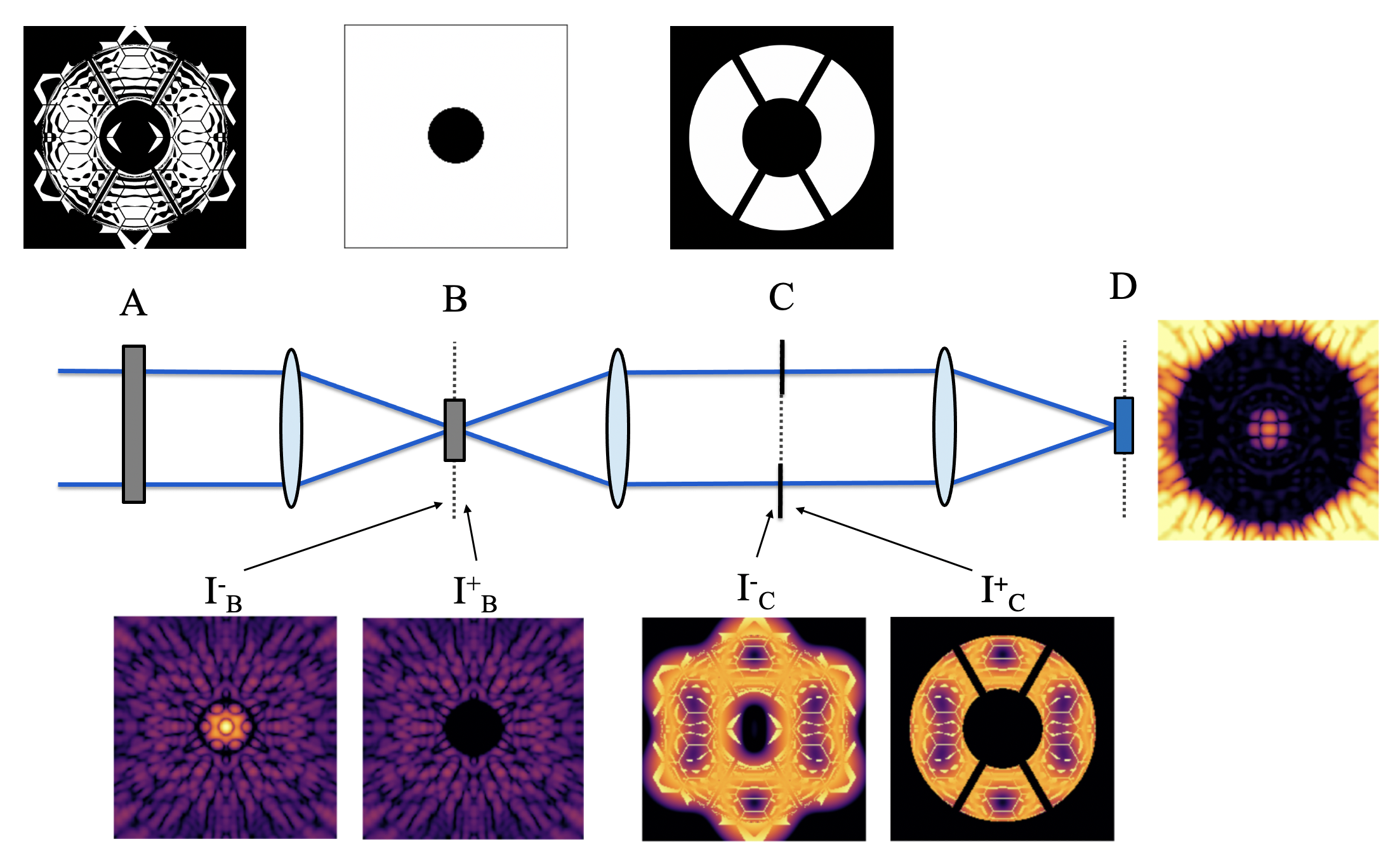
A schematic diagram of the APLC is shown in Figure 1, with an example of on-axis light propagating through each of the coronagraphic masks. The APLC optical layout consists of an apodizer in the pupil plane A that modulates the optical beam in amplitude, a downstream focal plane mask (FPM) in plane B that occults the on-axis point-spread-function (PSF) core, and a Lyot stop (LS) in the relayed pupil plane C that blocks the light diffracted by the FPM to form the coronagraphic image on a detector located in the re-imaged focal plane D.
In this work, we present a publicly available software toolkit developed to explore the design of APLCs. We provide a broad overview of the APLC-optimization package and the approaches used in Section 2. In Section 3, we provide examples of existing coronagraph designs optimized by our software. In Section 4, we present an application of the toolkit for a parameter study in the case of a 6m aperture off-axis space telescope, producing APLC solutions for different segment sizes and analyzing their performance (contrast, inner and outer working angles, throughput), as well as WFE tolerances in Section 5. We conclude with Section 6.
2 The APLC-Optimization toolkit
APLC-Optimization is a software toolkit developed by the SCDA (Segmented Coronagraph Design Analysis) research team at the Space Telescope Science Institute (STScI) for the purpose of exploring APLC solutions for arbitrary telescope apertures. It uses a numerical optimization method to find transmission-maximizing binary apodizers for a given combination of design constraints (such as the contrast goal, dark zone inner working angle and outer working angle, spectral bandwidth, telescope pupil, occulting mask, and Lyot stop profile). The object-oriented approach of the APLC-optimization toolkit simplifies the interface for extensive parameter space studies and enables flexibility for implementing various mask architectures, including features such as mirror segment gaps and struts.
The simulation of all propagations is performed with HCIPy[1], using the semi-analytical Lyot coronagraph propagation method described in Soummer et al. (2007)[4]. For efficiency, the code only propagates light to the part of the dark zone that is used for the constraints by treating the area outside of this focal-plane mask as fully transmissive. For the numerical optimization itself, we rely on the Gurobi111https://www.gurobi.com/products/gurobi-optimizer/ solver to compute the apodizer mask with maximized off-axis transmission.
The APLC-Optimization package includes complete documentation of all classes and functions. The core software package, example notebooks, and documentation are all publicly hosted through the STScI GitHub organization222https://github.com/spacetelescope/aplc_optimization.
2.1 Apodizer Optimization Method
A detailed description of our complete numerical optimization method is provided in Por et al. 2020[5]. Specifically, the optimization problem maximizes the peak of the non-coronagraphic image while simultaneously constraining the intensity of the broadband coronagraphic image in the dark-zone region. It forces it to be lower than the desired raw contrast limit, which is measured as the relative intensity with respect to the peak intensity of the non-coronagraphic image.
Por et al. 2020 further describes the methods we use to reduce the dimensionality of the optimization problem and significantly speed up the optimization process. These include exploiting symmetries in the underlying problem and a progressive refinement algorithm that relies on the binary structure of the masks to progressively upscale low-resolution solutions, at minimal cost. Altogether, these techniques significantly reduce computation time and memory usage, increasing the ease of larger and more intricate mask optimizations and parameter space explorations[5].
2.2 Parameter space surveys
The toolkit features a survey mode designed to simplify the organization, execution, and evaluation of extensive parameter space studies. Design surveys are performed using “optimization launchers”, wherein the user defines a set of design parameters to be surveyed. These include a list of telescope aperture specifications, Lyot stop dimensions, focal-plane mask sizes, tolerance constraints, and contrast and bandwidth goals. At the same time, the user can also set the parameters for the optimization method, such as whether to turn on the adaptive algorithm, ignore certain symmetries in the optimization problem, or set the number of threads to be used by the solver. Any unspecified parameters are set to reasonable default values.
Launcher templates are provided for a number of realistic telescope configurations, such as LUVOIR-A[6], HiCAT[7], and Gemini/GPI[8]. Once launched, the toolkit produces all the necessary input files defining the telescope apertures and intermediate masks; it then calls a routine to write a collection of “driver” files (one for each parameter combination) to be executed in queued batches on a computing server. These driver files, along with all logging files, are bundled together in a “survey” folder, providing a complete paper trail for the entire collection of optimizations so that each distinct optimization can be checked or repeated in the future. Once each optimization program completes, the apodizer solution is saved to disk, and an analysis module is automatically run. This analysis module produces a PDF file containing a design summary and several relevant plots so that the design can be evaluated immediately after optimization.
2.3 Design robustness to Lyot stop misalignments
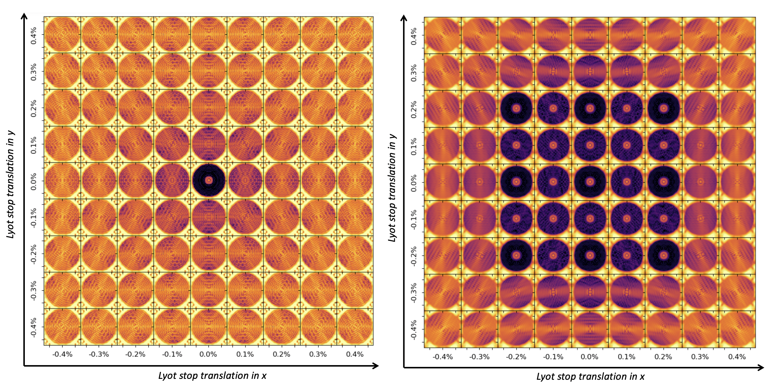
Future space-based telescopes will require designs that operate in broadband light and are insensitive to fabrication and alignment errors. The toolkit approaches the development of APLC designs robust to Lyot stop misalignments by optimizing the apodizer for multiple translated versions of the Lyot stop simultaneously. Figure 2 shows the Lyot stop misalignment sensitivity for APLC designs without (left) and with (right) built-in Lyot stop robustness properties. For the robust design (right panel in Figure 2), the optimization is performed using a set of 9 Lyot stops in a 3 x 3 grid, centred on the nominal Lyot stop position. The two figures show a grid of the coronagraphic images for different translations of the Lyot stop mask. While the non-robust design only produces a dark zone when the Lyot stop is centered on its optimal on-axis position, the design optimized with increased robustness to Lyot stop misalignment produces a dark zone for multiple, translated versions of the Lyot stop.
 |
3 Case studies
In this section, we highlight two usage cases of the APLC-Optimization package to produce optical designs for current-generation high-contrast imaging instruments. The first usage case, HiCAT, shows that the toolkit can (1) handle segmented-telescope pupils with non-simple geometries that include features such as support struts (“spiders”) and central obscurations, and (2) produce designs capable of achieving competitive raw contrast levels necessary for future large space-based coronagraphic missions. The second usage case, GPI, shows that the toolkit can perform similar optimizations on ground-based high-contrast imaging instruments.
3.1 HiCAT
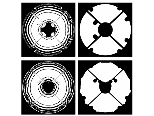
The High-contrast imager for Complex Aperture Telescopes[7] is a coronagraphic instrument and optical design testbed developed to simulate and study segmented aperture geometries for applications on future large space-based observatories. It features a 37 hexagonal segment IrisAO deformable mirror (DM) which acts as a primary mirror simulator, two Boston Micromachines Kilo-DMs used to perform closed-loop wavefront sensing and control, a Zernike mask and wavefront sensor used to perform low-order aberration wavefront control [9], and modular optics mounts which can accommodate different mask geometries in each of the optical planes of propagation of the instrument - including an apodizer mount, a focal-plane mount (e.g., pinhole, knife-edge), and a LS mount. The APLC-Optimization toolkit is our primary software infrastructure for developing apodizer designs for the HiCAT testbed (see Figure 3 for an example HiCAT apodizer design). We have used the package to produce mask designs which can achieve nominal raw contrasts on the order of to in an annular dark zone down to an IWA of 4 over a spectral bandpass of up to 15%. HiCAT is an important step on the path to achieving the nominal raw contrast of , which is the aspirational target of future space-based coronagraphic instrument concepts [3].
3.2 GPI
The Gemini Planet Imager[10] is an integral field spectrograph and coronagraph that is in the process of being upgraded and moved from its current mount behind the Cassegrain focus of the 8.1m Gemini South Telescope to a similar position on the telescope’s twin, Gemini North, as part of the instrument’s upgrade process - GPI 2.0 [11]. The APLC-Optimization toolkit was recently used to develop new apodizer and Lyot stop masks as part of the GPI 2.0 upgrade[8, 12]. These updated apodizers were optimized to achieve better high-contrast imaging performance, such as deeper raw contrast at the IWA of the dark zone, and increased robustness to Lyot stop misalignments. Some of the matching LS masks developed to go with the new apodizers (see Figure 3) were intentionally symmetrized in order to reduce the computational overhead of the optimization (by up to a factor of 4, as described in Section 2.1). This allowed the optimizations to bypass a memory bottleneck encountered in the optimization process caused by the asymmetry of the original LS designs due to the masking of the dead actuators on the Gemini Telescope’s deformable mirror. These new coronagraphic masks have been lithographically printed by Advanced Nanophotonics Inc.333https://www.advancednanophotonics.com/[13] and will be ready for use when GPI 2.0 goes on-sky in 2023.

|
 |
4 Segment Size Survey for a 6 m off-axis segmented space telescope
Segment size is a key parameter in the design of segmented telescope apertures. Determining the optimal number of segments to fill a particular aperture size involves a complicated trade-off between many factors, including diffraction effects, fabrication and complexity of individual support, versus the complexity of telescope alignment and control. Concerning the future Large IR/Optical/UV telescope recommended by the NASA Astro 2020 Decadal survey, the committee concluded that “a target off-axis inscribed diameter of approximately 6 meters provides an appropriate balance between scale and feasibility.”[3]. In order to help optimize such a configuration, we conduct a preliminary study of APLC performance for apertures with a wide range of segment sizes, at a fixed telescope inscribed diameter of 6 m.
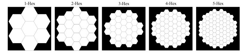
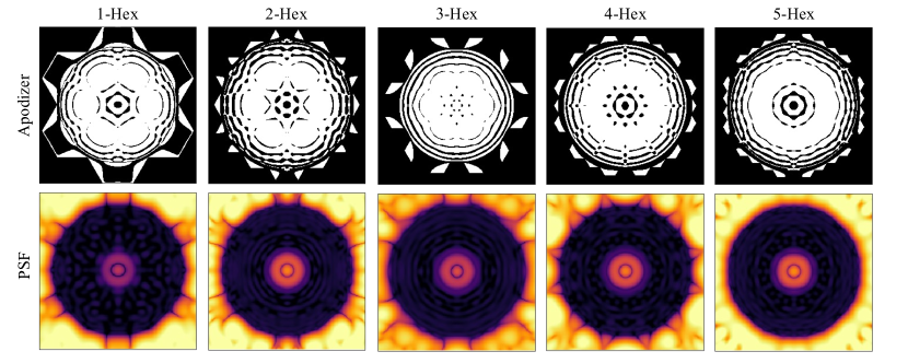
In this section, we summarize a survey of APLC solutions for five off-axis hexagonal segmented apertures made of segments with varying sizes. Figure 4 shows the five reference apertures considered, with decreasing segment size from left to right. The apertures are comprised of hexagonal segments organized in N = 1, 2, 3, 4, and 5 hexagonal concentric rings around a central segment. For the N = 3, 4 and 5 ring apertures some of the segments in the outer rings have been omitted in order to maximize the diameter of the inscribed circle with respect to the overall diameter. This results in a circularization of the pupils which has been shown to be advantageous for coronagraphy[14].
 |
To be in line with the recommendations of the Astro2020 Decadal Report, each aperture design is off-axis with an inscribed primary mirror diameter of 6 m. The gaps between segments are fixed across the designs to 60 mm. The key aperture design parameters are listed in Table 1. Each aperture is matched to a circular unobscured Lyot stop, with an outer diameter (OD) set to 98 of the circle inscribed in the aperture perimeter. This design decision was informed by previous experience that APLC performance is best with a slightly undersized Lyot stop[15].
| Design | 1-Hex | 2-Hex | 3-Hex | 4-Hex | 5-Hex |
|---|---|---|---|---|---|
| Circumscribed diameter (m) | 7.9445 | 7.2617 | 7.7231 | 7.1522 | 6.8526 |
| Inscribed diameter (m) | 6.0023 | 5.9994 | 5.9899 | 5.9937 | 5.9941 |
| Segment size (flat-to-flat) (m) | 2.6442 | 1.4475 | 1.1932 | 0.8511 | 0.6607 |
| Number of segments | 7 | 19 | 31 | 55 | 85 |
| Gap size (m) | 0.006 | 0.006 | 0.006 | 0.006 | 0.006 |
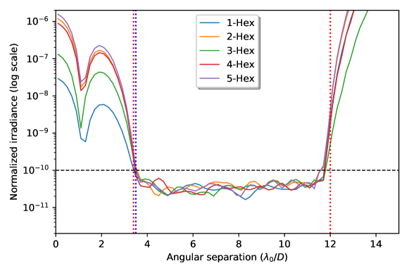
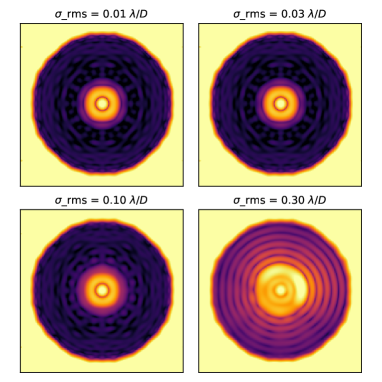
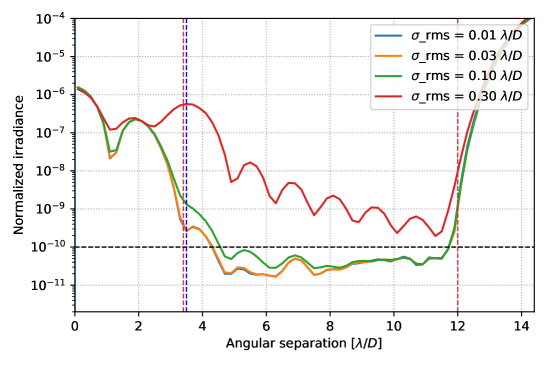
The designs are optimized for a contrast dark zone for a 10 relative spectral bandwidth. The outer perimeter of the annular dark zone (the effective OWA) is 12 /D. We set the inner edge of the dark hole to be smaller than the edge of the focal-plane mask in order to improve the design robustness to stellar diameter and low-order wavefront aberrations[16]. Figure 7 illustrates the influence of tip-tilt jitter on the contrast performance for the 5-Hex non-robust design across the 10% bandwidth, showing the design is robust to lower levels of tip-tilt jitter (achieving an average contrast for a tip-tilt rms of ), while for larger tip-tilt errors, the contrast in the dark zone starts to degrade.
The optimizations were run with these constraints at three wavelengths centered around over a 10% bandpass (note that while only three wavelengths are used for the optimizations, the broadband profiles illustrated in Figure 5 are averaged over 11 wavelengths). Figure 5 shows both the apodizer mask solutions and the post-coronagraphic PSF images for the APLC designs discussed above. Figure 6 shows the radially averaged PSF profiles showing that all designs meet the 10-10 contrast goal and exceed it at most angular separations.
 |
 |
|
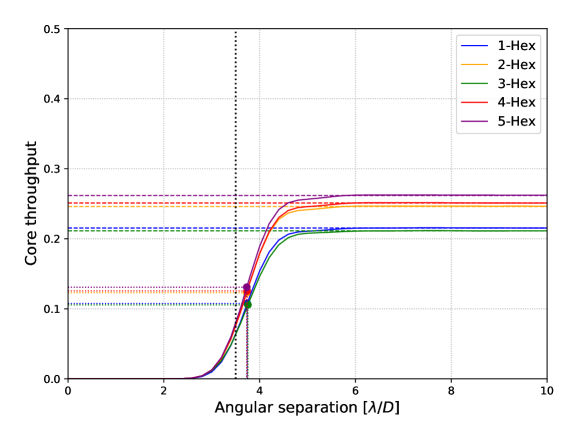 |
We show the core throughput for each of these designs in Figure 8, which is defined here as the ratio between encircled energies of the non-coronagraphic PSF and the off-axis (planet) coronagraphic PSF. We note the throughput performance between the 1-Hex and 3-Hex, and the 2-Hex and 4-Hex are very similar: both within 2% of each other. This is because the design throughput is sensitive to the shape of the aperture perimeter. The 1-Hex and 3-Hex designs demonstrate the worst throughput performance due to their larger overall aperture diameter with respect to the diameter of the inscribed circle (ratio of 1.32 and 1.29, respectively). Meanwhile, the 5-Hex design, which has the smallest ratio between the inscribed and circumscribed diameter (1.14), has the best throughput performance. This is because the apodized pupil is directly related to the inscribed circle[17]. Light that is incident on the outer edges of the segmented primary, outside the inscribed diameter, is mostly discarded, resulting in a lower core throughput.
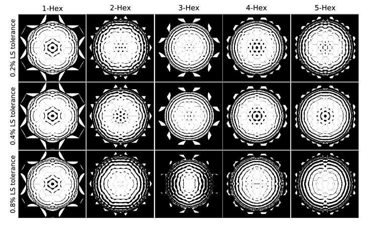
In addition to the “non-robust” designs above, we seek three further solutions for each of the apertures in Figure 5, optimized with 0.2, 0.4 and 0.8 Lyot stop misalignment tolerances. Figure 9 shows the apodizer solutions for each of the N-Hex telescope apertures with built-in robustness properties. Differences in the apodization pattern are apparent where the optimizer has added features to accommodate Lyot stop translations in this range.
 |
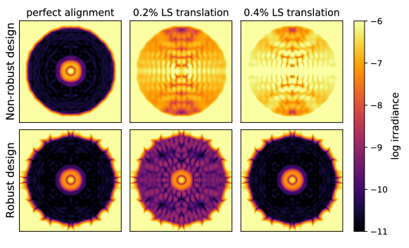
Compared to the non-robust designs, which are optimized for a single on-axis Lyot stop, the robust designs are optimized for a set of 9 Lyot stops in a three-by-three grid centered around the on-axis position. Figure 10 and 11 show examples of the post-coronagraphic PSF images and normalized irradiance profiles for two designs (5-Hex geometry), one with and one without built-in Lyot stop robustness properties, in the presence of different horizontal translations of the Lyot stop. They illustrate that while the non-robust design generates a dark zone only for a perfectly centered Lyot stop, the robust design produces dark holes for different Lyot stop offsets, illustrating its ability to yield contrast in the presence of a slightly decentered Lyot stop. While these solutions are very promising in terms of robustness to LS misalignments, they come at the cost of decreased throughput. Figure 12 shows the Core throughput for the four 5-Hex APLC designs, illustrating the trade-off between design robustness and core throughput.
 |
 |
 |
5 Comparative Wavefront Error Sensitivity Analysis
In our previous analysis of the N-Hex designs, we assumed an idealized scenario of a system without any wavefront errors. In a real optical system however, aberrations will lead to a degradation of image quality. Coronagraphic instruments are particularly sensitive to wavefront errors in the optical system, which contaminate the focal-plane image. For segmented telescopes, a significant component for wavefront errors is misalignment between individual segments. In this section, we study the performance of the five N-Hex aperture and coronagraph designs to these kinds of segment-level aberrations. In particular, we use the PASTIS sensitivity analysis to set segment-level piston tolerances[18, 19]. We then expand this analysis to custom thermal aberration modes on the segments, which provides the tolerances for thermal gradients for a requested static target contrast.
The PASTIS approach includes building a calibration matrix by propagating known input wavefront aberrations through an end-to-end model of the telescope and coronagraph, and measuring the dark-hole intensity. We then inverse this calibration matrix to calculate the tolerances required for each segment, expressed as a standard deviation. We produce spatially dependent requirement maps (instead of describing the wavefront tolerance globally for the total pupil). Figure 13 shows the segment-level piston tolerances for the five designs required to achieve a statistical mean contrast of in the coronagraphic dark zone, over a normally distributed set of aberration maps.
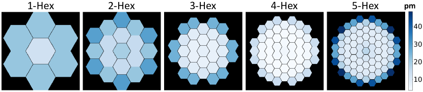
Out of the five designs considered, we find that the 4-Hex design has the most stringent requirements, and the 5-Hex has the most relaxed piston requirements overall. In general, we find that for the designs with increased segment numbers, the inner segments have more stringent tolerance requirements than the outer ones. We also observe that the spread between the most and least tolerant segments is the largest for the 5-Hex design, while it is the smallest for the 4-hex design. In a next step, we validate these tolerance maps by performing end-to-end optical Monte Carlo (MC) simulations. For the validation of one tolerance map, we draw segmented aberration maps, where the coefficient of the piston aberration is drawn randomly from a normal distribution with a zero mean and standard deviation given by the respective map. These aberration realizations are then propagated through an optical simulator and their average DH contrast measured. The distribution of these measurements is shown in the histogram in Figure 14.
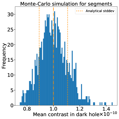
In the resulting histogram, we calculate a mean value that matches the requested statistical mean contrast, and the standard deviation of the contrast distribution is equal to the analytically calculated value of this optical system as computed with the PASTIS model[18].
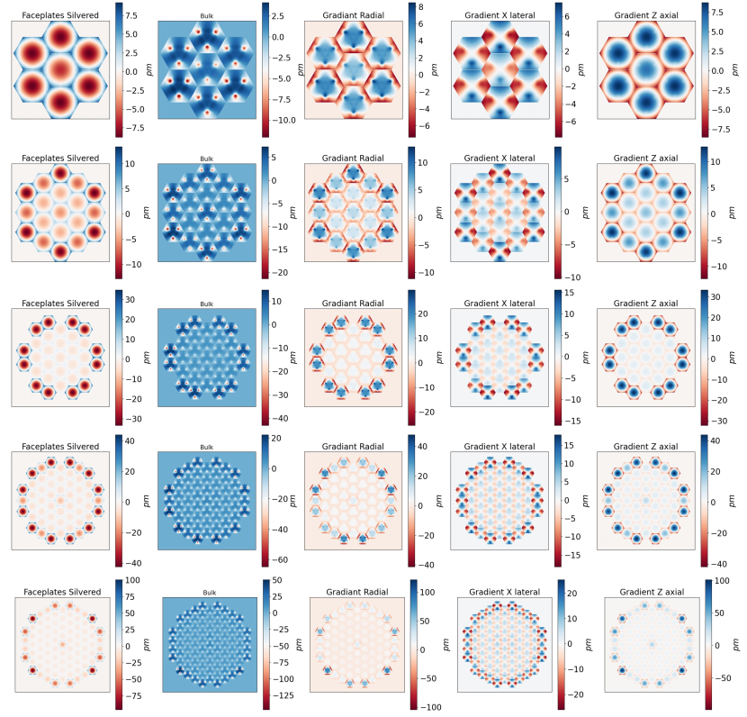
We extend the PASTIS approach to study the thermo-elastic effect associated with the primary mirror back plane support structure under thermal influence. The mirror mounting pads have direct contact with the mirror substrate and induce surface deformations on the order of picometers which directly impacts the performance of the coronagraph. We use five kinds of segment-level surface disturbances obtained from L3 Harris Technologies[21] as the finite elements for our analysis. These finite elements are the segment-level response when a 1 mK temperature gradient is applied along different axial directions of a segment; they are more likely to occur than segment-level Zernike polynomials. We use these finite elements in the PASTIS sensitivity analysis like in the previous paragraph and derive segment-level temperature requirements to maintain an average dark hole contrast of . The results in terms of surface deformation errors are shown in Figure 15.
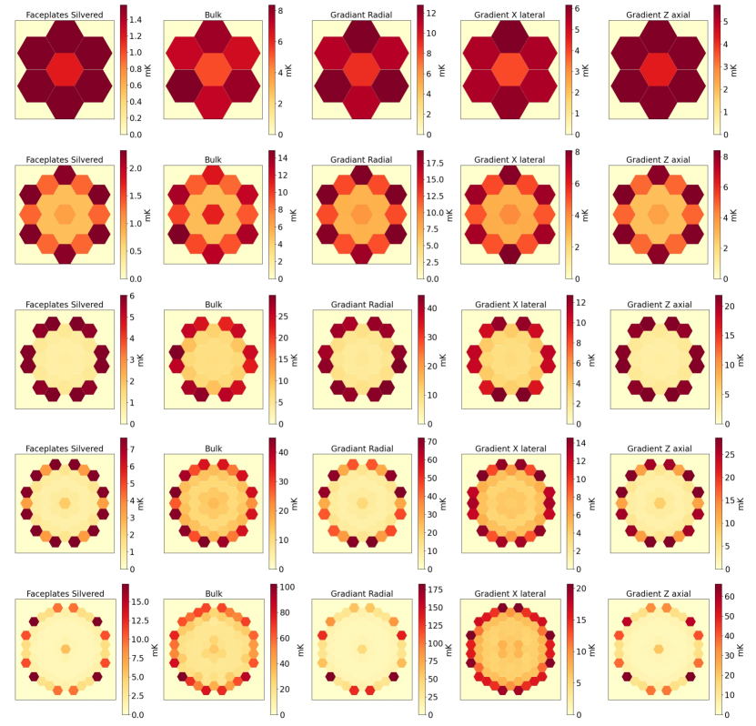
Since the thermal aberration modes establish a relation between the influence of a thermal gradient and the resulting surface deformation, we can use them to convert the surface requirements in Fig. 16 into requirements expressed as a tolerable temperature change standard deviation. These physical-unit tolerance maps are displayed in Figure 16 for all five designs.
6 Conclusions
In this paper, we have presented APLC-Optimization, a coronagraph design survey toolkit written in Python for optimizing and exploring APLC solutions for any telescope geometry and science goal. This toolkit simplifies the organization, execution and analysis of extensive design parameter space surveys. It allowed us to establish relationships and trade-offs between design parameter combinations and identify new design approaches for telescopes with various performance requirements. A notable feature of the design toolkit is the possibility to include robustness to LS misalignments as an optimization parameter. In this way, the resulting apodizers still perform reasonably well in terms of contrast for a small range of off-center LS positions.
We showed examples of apodizer masks optimized by this toolkit for HiCAT and Gemini/GPI, illustrating its ability to produce competitive designs for both space- and ground-based high-contrast imaging instruments. This includes the capability to handle segmentation and secondary support features with excellent contrast performance and optimized planet throughput in 10-15% bandwidths.
Finally, we presented an application of the toolkit for the case of a 6 m aperture off-axis segmented telescope. We performed a design survey investigating the effect of varying segment sizes on the overall coronagraph performance. The investigated telescope designs all have a 6 m inscribed diameter aperture with a varying number of hexagonally segmented rings, from to . Each of these five apertures were used to create optimized apodizers with and without baked-in robustness to LS misalignments.
While all of the prescribed APLC solutions reach the design DH contrast of and a reasonable throughput, we evaluated the five designs through a WFE sensitivity analysis used previously to derive the per-segment WFE tolerances of LUVOIR-A. In a detailed study for piston-only local aberrations, the PASTIS sensitivity analysis let us derive an individual WFE standard deviation per segment. Following the extended tolerancing approach of this method presented in Ref. 21, we derived first physical tolerances for thermal gradients.
These preliminary results indicate promising performance for the APLC on the next large space-based IR/O/UV flagship. The comparative analysis between the designs indicates that the 5-Hex design is the most promising in terms of maximum core throughput and WFE tolerance; however, further work is necessary to present a more thorough examination. Applications like these underline the relevance of optimization tools like the one presented in this paper, as they will enable us to expand on these pre-fatory results in the near future.
 |
 |
For more quantitative details on the methodology, see Sahoo et al. 2022 [21].
Acknowledgements.
This work was funded in part by NASA Exoplanet Exploration Program’s (ExEPs) Segmented Coronagraph Design and Analysis (SCDA) study. E.H.P. is supported by the NASA Hubble Fellowship grant #HST-HF2-51467.001-A awarded by the Space Telescope Science Institute, which is operated by the Association of Universities for Research in Astronomy, Incorporated, under NASA contract NAS5-26555. The HiCAT optimization work was supported in part by the National Aeronautics and Space Administration under Grant 80NSSC19K0120 issued through the Strategic Astrophysics Technology/Technology Demonstration for Exoplanet Missions Program (SAT-TDEM; PI: R. Soummer). The GPI2.0 optimization work was funded by the STScI Discretionary Research Fund (D0101.90238). I.L. acknowledges the support by a postdoctoral grant issued by the Centre National d’Études Spatiales (CNES) in France. The Gemini Planet Imager 2.0 project upgrade is supported by the National Science Foundation under Grant No. AST-1920180, and also significantly supported by the Heising-Simons Foundation. A.S. acknowledges the support by the Ultra-Stable Telescope Research and Analysis (ULTRA) Program under Contract No. 80MSFC20C0018 with the National Aeronautics and Space. This research made use of HCIPy, an open-source object-oriented framework written in Python for performing end-to-end simulations of high-contrast imaging instruments.References
- [1] Por, E. H., Haffert, S. Y., Radhakrishnan, V. M., Doelman, D. S., van Kooten, M., and Bos, S. P., “High Contrast Imaging for Python (HCIPy): an open-source adaptive optics and coronagraph simulator,” in [Adaptive Optics Systems VI ], Close, L. M., Schreiber, L., and Schmidt, D., eds., 10703, 1112 – 1125, International Society for Optics and Photonics, SPIE (2018).
- [2] National Academies of Sciences, Engineering, and Medicine, [Exoplanet Science Strategy ], The National Academies Press, Washington, DC (2018).
- [3] National Academies of Sciences, Engineering, and Medicine, [Pathways to Discovery in Astronomy and Astrophysics for the 2020s ], The National Academies Press, Washington, DC (2021).
- [4] Soummer, R., Pueyo, L., Sivaramakrishnan, A., and Vanderbei, R. J., “Fast computation of Lyot-style coronagraph propagation,” Optics Express 15, 15935 (Jan. 2007).
- [5] Por, E. H., Soummer, R., Noss, J., and St. Laurent, K., “Exploiting symmetries and progressive refinement for apodized pupil Lyot coronagraph design,” in [Society of Photo-Optical Instrumentation Engineers (SPIE) Conference Series ], Society of Photo-Optical Instrumentation Engineers (SPIE) Conference Series 11443, 114433P (Dec. 2020).
- [6] The LUVOIR Team, “The luvoir mission concept study final report,” (2019).
- [7] Soummer, R., Por, E. H., Pourcelot, R., Redmond, S. F., Laginja, I., Will, S. D., Noss, J., Perrin, M., Pueyo, L., Sahoo, A., Petrone, P., Brooks, K. J., Comeau, T., Gontrum, R., Hagopian, J., Mugnier, L. M., N’Diaye, M., Nickson, B., Nguyen, M., Sauvage, J.-F., Scott, N., and Weinstock, S., “High-contrast imager for complex aperture telescopes (HiCAT): 8. Dark zone demonstration with simultaneous closed loop low-order wavefront sensing and control,” Society of Photo-Optical Instrumentation Engineers (SPIE) Conference Series (July 2022). In these proceedings.
- [8] Nguyen, M. M., Nickson, B., Por, E. H., Soummer, R., Hagopian, J., Macintosh, B., Chilcote, J., Pueyo, L., Perrin, M., and Konopacky, Q., “GPI 2.0: Optical Designs for the Upgrade of the Gemini Planet Imager Coronagraphic system,” in [Society of Photo-Optical Instrumentation Engineers (SPIE) Conference Series ], Society of Photo-Optical Instrumentation Engineers (SPIE) Conference Series (July 2022). In these proceedings.
- [9] Pourcelot, R., N’Diaye, M., Por, E. H., Noss, J., Carbillet, M., Laginja, I., Perrin, M., Pueyo, L., Redmond, S. F., Will, S. D., and Soummer, R., “Experimental stabilization of low-order aberrations on Lyot-type coronagraphs using a Zernike wavefront sensor,” Society of Photo-Optical Instrumentation Engineers (SPIE) Conference Series (July 2022). In these proceedings.
- [10] Macintosh, B., Graham, J. R., Ingraham, P., Konopacky, Q., Marois, C., Perrin, M., Poyneer, L., Bauman, B., Barman, T., Burrows, A. S., Cardwell, A., Chilcote, J., De Rosa, R. J., Dillon, D., Doyon, R., Dunn, J., Erikson, D., Fitzgerald, M. P., Gavel, D., Goodsell, S., Hartung, M., Hibon, P., Kalas, P., Larkin, J., Maire, J., Marchis, F., Marley, M. S., McBride, J., Millar-Blanchaer, M., Morzinski, K., Norton, A., Oppenheimer, B. R., Palmer, D., Patience, J., Pueyo, L., Rantakyro, F., Sadakuni, N., Saddlemyer, L., Savransky, D., Serio, A., Soummer, R., Sivaramakrishnan, A., Song, I., Thomas, S., Wallace, J. K., Wiktorowicz, S., and Wolff, S., “First light of the Gemini Planet Imager,” Proceedings of the National Academy of Science 111, 12661–12666 (Sept. 2014).
- [11] Chilcote, J., Konopacky, Q., De Rosa, R. J., Hamper, R., Macintosh, B., Marois, C., Perrin, M. D., Savransky, D., Soummer, R., Véran, J.-P., Agapito, G., Aleman, A., Ammons, S. M., Bonaglia, M., Boucher, M.-A., Curliss, M., Dunn, J., Esposito, S., Filion, G., Fitzsimmons, J., Kain, I., Kerley, D., Landry, J.-T., Lardiere, O., Lemoine-Busserolle, M., Li, D., Limbach, M. A., Madurowicz, A., Maire, J., N’Diaye, M., Nielsen, E. L., Poyneer, L., Pueyo, L., Summey, K., and Thomas, C., “GPI 2.0: upgrading the Gemini Planet Imager,” in [Society of Photo-Optical Instrumentation Engineers (SPIE) Conference Series ], Society of Photo-Optical Instrumentation Engineers (SPIE) Conference Series 11447, 114471S (Dec. 2020).
- [12] Por, E. H., Pueyo, L., and Soummer, R., “Joint optimization of multiple optical planes in a stellar coronagraph,” Society of Photo-Optical Instrumentation Engineers (SPIE) Conference Series (July 2022). In these proceedings.
- [13] Hagopian, J. G., Getty, S. A., Quijada, M., Tveekrem, J., Shiri, R., Roman, P., Butler, J., Georgiev, G., Livas, J., Hunt, C., Maldonado, A., Talapatra, S., Zhang, X., Papadakis, S. J., Monica, A. H., and Deglau, D., “Multiwalled carbon nanotubes for stray light suppression in space flight instruments,” in [Carbon Nanotubes, Graphene, and Associated Devices III ], Pribat, D., Lee, Y.-H., and Razeghi, M., eds., 7761, 57 – 66, International Society for Optics and Photonics, SPIE (2010).
- [14] Laurent, K. S., Fogarty, K., Zimmerman, N. T., N’Diaye, M., Stark, C. C., Mazoyer, J., Sivaramakrishnan, A., Pueyo, L., Shaklan, S., Vanderbei, R., and Soummer, R., “Apodized pupil Lyot coronagraphs designs for future segmented space telescopes,” in [Space Telescopes and Instrumentation 2018: Optical, Infrared, and Millimeter Wave ], Lystrup, M., MacEwen, H. A., Fazio, G. G., Batalha, N., Siegler, N., and Tong, E. C., eds., 10698, 889 – 905, International Society for Optics and Photonics, SPIE (2018).
- [15] Zimmerman, N. T., Riggs, A. J. E., Kasdin, N. J., Carlotti, A., and Vanderbei, R. J., “Shaped pupil Lyot coronagraphs: high-contrast solutions for restricted focal planes,” Journal of Astronomical Telescopes, Instruments, and Systems 2(1), 1 – 21 (2016).
- [16] N'Diaye, M., Pueyo, L., and Soummer, R., “APODIZED PUPIL LYOT CORONAGRAPHS FOR ARBITRARY APERTURES. IV. REDUCED INNER WORKING ANGLE AND INCREASED ROBUSTNESS TO LOW-ORDER ABERRATIONS,” The Astrophysical Journal 799, 225 (jan 2015).
- [17] Laurent, K. S., Fogarty, K., Zimmerman, N. T., N’Diaye, M., Stark, C. C., Mazoyer, J., Sivaramakrishnan, A., Pueyo, L., Shaklan, S., Vanderbei, R., and Soummer, R., “Apodized pupil Lyot coronagraphs designs for future segmented space telescopes,” in [Space Telescopes and Instrumentation 2018: Optical, Infrared, and Millimeter Wave ], Lystrup, M., MacEwen, H. A., Fazio, G. G., Batalha, N., Siegler, N., and Tong, E. C., eds., 10698, 889 – 905, International Society for Optics and Photonics, SPIE (2018).
- [18] Laginja, I., Soummer, R., Mugnier, L. M., Pueyo, L., Sauvage, J.-F., Leboulleux, L., Coyle, L., and Knight, J. S., “Analytical tolerancing of segmented telescope co-phasing for exo-Earth high-contrast imaging,” Journal of Astronomical Telescopes, Instruments, and Systems 7, 015004 (Jan. 2021).
- [19] Laginja, I. and Leboulleux, L., “PASTIS v1.3.0.” Zenodo (Sept. 2019).
- [20] Laginja, Iva, Sauvage, Jean-François, Mugnier, Laurent M., Pueyo, Laurent, Perrin, Marshall D., Noss, James, Will, Scott D., Brooks, Keira J., Por, Emiel H., Petrone, Peter, and Soummer, Rémi, “Wavefront tolerances of space-based segmented telescopes at very high contrast: Experimental validation,” A&A 658, A84 (2022).
- [21] Sahoo, A., Laginja, I., Pueyo, L., Soummer, R., Coyle, L. E., Knight, J. S., and East, M., “Segment-level thermal sensitivity analysis for exo-earth imaging,” Society of Photo-Optical Instrumentation Engineers (SPIE) Conference Series (2022). In these proceedings.