Frequency-robust Mølmer-Sørensen gates via balanced contributions of multiple motional modes
Abstract
In this work, we design and implement frequency-robust Mølmer-Sørensen gates on a linear chain of trapped ions, using Gaussian amplitude modulation and a constant laser frequency. We select this frequency to balance the entanglement accumulation of all motional modes during the gate to produce a strong robustness to frequency error, even for long ion chains. We demonstrate this technique on a three-ion chain, achieving < 1% reduction from peak fidelity over a 20 kHz range of frequency offset, and we analyze the performance of this gate design through numerical simulations on chains of two to 33 ions.
I Introduction
Linear chains of trapped ions are one of the leading platforms for quantum computation in the near term. The application of Mølmer-Sørensen (MS) gates [1] on these systems has achieved some of the highest two-qubit entanglement fidelities to date, reaching above 99.9% while targeting the axial motional modes of a two-ion chain [2, 3]. To implement powerful quantum algorithms, like digital quantum simulation [4] and quantum error correction [5, 6, 7], one must extend these high-fidelity gates to systems of many physical qubits by, for example, increasing the length of the chain and individually addressing each ion [8, 9]. In this approach, the MS gates provide all-to-all connectivity between ion pairs, but the gate fidelity can suffer due to the residual spin-motion entanglement after the gate in the increased number of spectator motional modes [1].
There have been many successful demonstrations of high-fidelity MS gates by modulating the amplitude [8, 9, 10, 11, 12, 13, 14], frequency [15, 16], amplitude and frequency [17, 18], or phase [19, 20, 21] of the laser beams. These approaches have achieved 97% to 99.5% fidelity when targeting the radial modes of a two-ion chain, for which the tighter confinement than in the axial direction allows better cooling, less heating, and faster gates. The modulation techniques improve gate performance by eliminating the residual spin-motion entanglement for ideal experimental conditions and by adding robustness to this quantity in the presence of motional frequency error. For example, simulations of frequency-modulated gates maintain a 99% fidelity with a motional frequency error of 1.5 kHz for a two-ion chain [15], and optimizing over a distribution of gate parameters improves this level of robustness to at least kHz [22].
Nevertheless, motional frequency error remains an important error source in MS gates and their applications. Modulated MS gates attempt to minimize the sensitivity of the residual spin-motion entanglement to frequency error, and as a result, the amount of spin entanglement accumulated during the gate also gains robustness to this error. However, significant errors in the amount of accumulated spin entanglement can remain and create a purely coherent rotation error in spin space, which is especially damaging to the performance of quantum algorithms that involve many gates [23]. This sensitivity to rotation error was recently demonstrated by the repeated application of MS gates with a frequency offset on two-ion and four-ion chains [16].
For longer chains, the sensitivity to frequency error increases due to the higher density of motional modes. Further, the majority of frequency-robust gate designs become more difficult to implement due to more stringent experimental requirements, including the need to account for all modes by linearly increasing the number of optimized pulse-shape parameters with the number of ions [15]. Robust gate designs exist that reduce this requirement by only targeting closely spaced ions or a reduced set of motional modes [18], but the experimental requirements to implement these techniques can still grow with longer chains. Modulated gates on longer ion chains can require larger laser powers [16] and generally have a higher sensitivity to drift in the calibrated model parameters (e.g. motional frequencies, ion separation, laser power, and gate duration) that are used during the optimization of pulse-shape parameters [22].
In this paper, we develop and implement an MS gate with an analytic pulse shape that does not require optimizing a large set of pulse-shape parameters yet is still broadly robust to motional frequency error, even for long ion chains. We perform amplitude modulation during our gate with a simple, Gaussian time dependence that strongly suppresses residual displacement errors in all modes, as long as the detuning from each mode remains sufficiently large. While many studies have demonstrated error suppression using amplitude modulation, including modulation that resembles a Gaussian [17, 18, 14], we also select a specific, constant detuning that balances the amount of entanglement accumulation during the gate from all motional modes and provides robustness to this source of coherent gate error. With the ability to adjust the detuning without significantly impacting displacement errors, we are free to tune the laser frequency to a point where the derivative in the entanglement accumulation with respect to frequency goes to zero. This produces a gate that is first-order insensitive to frequency error, resulting in regions of broad robustness to this error. Our protocol is simple to realize experimentally, as we can optimize performance by calibrating only two pulse-shape parameters: the constant detuning and the peak Rabi rate. As a result, our gate design has a low classical computational overhead, facilitating its adoption on other trapped ion quantum processors and making it suitable for systems suffering from moderate amounts of drift. We demonstrate the frequency robustness of our gate on a three-ion chain and analyze this robustness in numerical simulations for chains of up to 33 ions.
This work is done on the Quantum Scientific Computing Open User Testbed, QSCOUT. We use qubits encoded in the hyperfine clock states of 171Yb+ ions trapped in a linear chain on a surface trap. Gates are site-selectively driven with an optical Raman transition. Details of the apparatus are described in previous work [24].
II Gate Design
II.1 MS Gate Model
We model the application of an MS gate on two ions that are part of a linear chain of ions in a surface trap using the Hamiltonian,
| (1) |
which is in a rotating frame with respect to the atomic and trap degrees of freedom. The collective spin operator has the form: , where is the Pauli spin operator for the -th ion targeted by the gate. The Lamb-Dicke parameter can differ for each ion and each motional mode, and is the Rabi rate of the carrier transition for both ions. In this work, is a time dependent parameter of the drive field, while is effectively held constant in time for each mode. The operators and are the raising and lowering operators, respectively, for a harmonic oscillator that represents the motional mode of the ion chain with angular frequency . During the gate, a dual-tone laser illuminates the ions with detunings from their blue and red motional sideband transitions, respectively, where the parameter is the detuning of the blue-detuned laser tone from the carrier transition. For simplicity, we have made the Lamb-Dicke approximation: . We have also neglected the carrier transition and the far-off-resonant sideband transitions with detunings larger than .
Since the Hamiltonian acts on each motional mode independently, we can write the propagator as a product over motional modes:
| (2) |
and the exact analytic solution for is [1, 25],
| (3) |
The displacement operator is conditioned on the spin state of the targeted ions, and describes the phase-space trajectory of the ion chain. The phase , which governs the amount of spin entanglement accrued during the gate, is real and positive (negative) for clockwise (counter-clockwise) trajectories.
To gain an intuitive picture of the gate dynamics, we express the phase-space trajectory of each motional mode in terms of the parameters of ,
| (4) |
where corresponds to the end of the gate. From this equation, we see that is proportional to the Fourier transform of evaluated at , assuming that is zero before () and after () the gate. This is a key insight that will aid our choice of pulse shape for frequency-robust gates, as discussed in section II.3.
In this study, we focus on the robustness of MS-gate performance to a frequency error that is applied to both laser tones and moves them symmetrically with respect to the carrier transition, resulting in new carrier detunings: and sideband detunings: , for the blue-detuned and red-detuned tones, respectively. Equivalently, this frequency error can be interpreted as a common change in the motional frequency of each mode: . Although other error sources can affect gate performance, such as laser power fluctuations and anomalous heating [26, 27], we choose to focus on frequency error due to the high sensitivity of gate performance to this error [25], especially in the context of long ion chains with many closely spaced motional modes.
II.2 Performance Metrics
We use the state fidelity as the figure of merit for gate performance, which can be computed by wavefunction overlap:
| (5) |
where is the wavefunction of the ion chain at the end of the gate and is the target state. We assume that we perfectly initialize the ions in the ground spin state and laser cool them to reach the motional ground state . The state of the ion chain after the gate is then , and we choose to target the state , a maximally entangled spin state and the motional ground state, as any residual displacement after the gate leads to spin-motion entanglement.
For ideal gate performance , we require the propagator at the end of the gate ( to take the following form: , where is the rotation angle of the gate. For our choice of initial and final states, the ideal gate is accomplished for,
| (6a) | |||
| (6b) | |||
Although is a sufficient metric for gate performance, we find that it is illustrative in this work to decompose the state fidelity into two contributing terms: displacement error and rotation-angle error , which arise from inequalities in equations (6a) and (6b), respectively. In the next two sections, we derive the contribution to the state infidelity from each error separately, where the sum of these errors,
| (7) |
is approximately equal to the state infidelity: , for small errors ( and ).
II.2.1 Displacement Error
Displacement error occurs when the coherent displacement at the end of the gate is non-zero, , and leads to residual spin-motion entanglement. In the phase-space trajectory picture, a gate with no displacement error for a particular mode will produce a closed curve, and any residual displacement (or open curve) contributes to the gate error. We call this contribution the displacement error for mode . As accomplished in several previous works, including [13, 15, 22, 21], we design gates that are robust to frequency errors for this error mechanism by shaping the laser pulse.
We derive an expression for the displacement error from each mode by acting the displacement operator for the gate on the initial state and computing the wavefunction overlap with the target state: . In the spin basis {}, the operator has four eigenvalues: , , , and , corresponding to the spin states , , , and , respectively. In terms of these eigenvalues,
| (8) |
and the total displacement error is,
| (9a) | |||
| (9b) | |||
If we assume the Lamb-Dicke parameters are equal for each ion and mode involved in the gate (), then the eigenvalues of are , and from the equation above, we find that for small errors.
II.2.2 Rotation-angle Error
Rotation-angle error is error in the entangling phase accumulated at the end of the gate. In the phase-space trajectory picture, this can be visualized as the area enclosed by the curves. In previous works, most gate designs do not explicitly target solutions that are robust to rotation-angle error caused by motional frequency drift. In this work, we utilize the contributions from multiple motional modes in order to derive a gate in which the entangling phase is independent to first order in symmetric detuning offset.
We derive an expression for the rotation error by acting the spin-entangling operator for the gate on the initial state and computing the wavefunction overlap with the target state: . Since the spin-entangling operator is independent of the motional state, we only require that the phase accrued during the gate is equal to to achieve an MS gate, as shown in equation (6b). Therefore, any additional phase results in the rotation of the target state, up to an arbitrary global phase, and the rotation error is,
| (10) |
II.3 Gaussian Pulse Shape
The robustness of our gate design to motional frequency error relies on the specific shape of the pulse amplitude during the gate, which we describe by a time-dependent Rabi rate . From section II.2.1, we see that the state infidelity grows linearly with the residual displacement of each mode . To reduce these contributions, we note that is proportional to the Fourier transform of evaluated at , as seen in section II.1, and we choose to employ a truncated-Gaussian pulse shape,
| (11) |
where is the peak Rabi rate, and is the Gaussian width. To understand the effect of this pulse shape, we assume that is sufficiently small () such that we can ignore the truncation of and extend the limits of integration in equation (4) for to all times,
| (12a) | |||
| (12b) | |||
where for all . Here, we see that the Gaussian-like pulse shape guarantees that the displacement error from each mode will exponentially decay with . For the appropriate choice of detuning, this can strongly suppress contributions to from the modes primarily driving the gate and almost entirely eliminate contributions to from far-detuned "spectator" modes.
II.4 Mode Balancing
Many MS-gate implementations, including the standard gate with a constant detuning and Rabi rate [1], suffer from the displacement error caused by spectator modes, and the gate performance degrades when the detuning of the mode primarily targeted by the gate has a similar magnitude as the detuning from the other modes. However, since the Gaussian pulse shape strongly suppresses , as discussed in section II.3, we have the freedom to detune close to multiple modes without suffering from large displacement errors. In this section, we take advantage of this freedom and determine a choice of detuning that not only maintains the suppression of but also reduces the rotation-angle error .
While staying sufficiently far away from all modes () to suppress , we aim to balance the contributions to from all modes, such that frequency errors that increase the contribution to from some modes are cancelled to first-order by the decrease in the contribution to from the other modes. In general, the detunings that balance the contributions to from all modes can be found by solving the following equation for ,
| (13) |
This equation can be solved numerically to implement gates for which is first-order robust to frequency error. At least for mono-species ion chains, solutions to equation (13) exist for all pairs of ions.
Although solving equation (13) is straightforward and numerically efficient, we can search for approximate solutions to further simplify the design and implementation of this gate. In the region of between two neighboring modes and , we can find an approximate solution by neglecting the contribution to from all other modes because the -th term in the sum becomes large near and tends to dominate all other terms. We also find that and have the same sign in this region, such that solutions to equation (13) are likely to be found when the products and have opposite signs. To the extent that these products have similar magnitudes, the two modes make similar contributions to the gate when , and we can expect to find a solution to equation (13) that is close to the midpoint between modes and : . In practice, one can use this value of as a starting point and experimentally calibrate as we describe in section III.3.
II.5 Gate Comparison
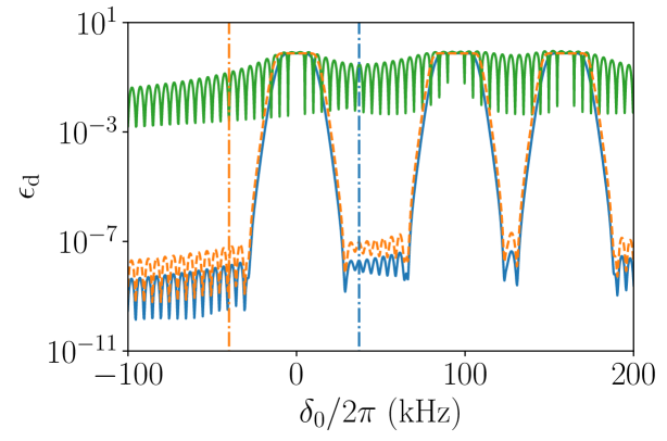
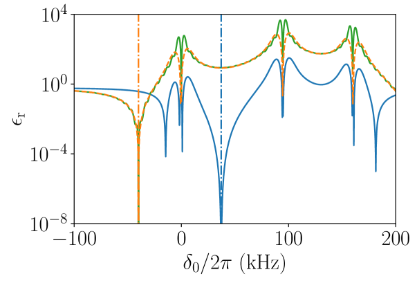
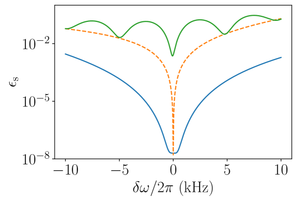
To demonstrate the robustness to frequency error of the balanced Gaussian gate, we simulate MS gates with three different pulse shapes subject to the symmetric frequency error and compute the contributions to the state infidelity from displacement error and rotation-angle error for each pulse. We compare the balanced Gaussian pulse, which has a detuning that solves equation (13), with a standard Gaussian pulse and a square pulse (constant Rabi rate during the gate) that are both detuned below the lowest motional mode. The duration of each gate is 200 s and the width of each Gaussian pulse is s. Being a small fraction of the pulse length, this choice of creates Gaussian-like pulses with small truncation effects.
We provide a concrete example for this comparison by simulating each gate on the outer ions of a three-ion chain with an ion separation of m and radial trapping frequencies of MHz and MHz in the orthogonal radial-a and radial-b directions, respectively. These trapping frequencies correspond to the motional frequency of the center-of-mass (highest) mode in each direction and have values that are typical for the surface trap of the QSCOUT testbed. We also assume the laser -vector is aligned at a 45 angle between the two radial directions, and we neglect any excitation of the axial motional modes, which will have a large detuning compared to the radial modes during the gate and are orthogonal to the -vector of the laser.
We design the balanced Gaussian gate by targeting the lowest two radial modes: the zig-zag () and tilt () radial-b modes, which have a splitting of kHz. The targeted ions have Lamb-Dicke parameters that are equal in the zig-zag mode, while being equal and opposite in the tilt mode, such that the products and have opposite signs and are approximately equal in magnitude. We then solve equation (13) in the region between these modes and obtain a detuning of kHz above the lowest frequency mode (zig-zag). For the standard Gaussian and square gates, we choose a detuning of kHz. As a final step, we select the peak Rabi rate for each gate separately to guarantee at the chosen detuning. The frequency error is defined relative to these nominal detunings for each gate.
Figure 1 shows the simulated values of and for the three different pulse shapes as a function of the detuning from the lowest motional mode. The Gaussian pulse shape (dashed orange and solid blue) suppresses displacement error as long as the gate is performed sufficiently far from all motional modes. By contrast, the square pulse gate (solid green) has narrow minima, and relatively high displacement error persists at all detunings in the range displayed. A broad dip in the rotation-angle error is apparent for the balanced Gaussian gate (solid blue) when the derivative with respect to detuning of the sum of contributions of multiple modes goes to zero. Intuitively, this can be described by the fact that as the detuning moves in one direction away from the optimal point the contribution from one mode becomes smaller but the contribution from the other mode becomes larger. By contrast, the standard Gaussian gate (dashed orange) and the square gate (solid green) only have narrow dips in rotation-angle error and thus have a small detuning range over which the target phase is accumulated. For small frequency errors, the state infidelity for each Gaussian pulse is strongly dominated by the contribution from the rotation-error . Figure 1c shows for each pulse shape over a range of experimentally relevant frequency errors, demonstrating the improved robustness to when using the balanced Gaussian pulse shape.
III Gate Implementation
III.1 Gate Parameter Selection
In addition to choosing the correct detuning to balance the contributions of multiple motional modes, the time-domain standard deviation, , of the truncated Gaussian pulse shape is a free parameter that may be tuned to optimize the gate performance. This may be done numerically or empirically given sufficient intuition about the contributions to gate error. In particular, we find that optimal value of for robustness to frequency error depends on the detuning from the closest two motional modes. On the one hand, the truncation of the Gaussian lying outside of the pulse duration leads to some amount of square pulse character with an abrupt pulse turn on. This truncation effect and square pulse character lead to some residual displacement error, especially when the Gaussian width becomes comparable to the gate time (). This error can be seen as the oscillating floor in the plot of in Fig. 1a. On the other hand, displacement error can become large when is small enough that becomes significant. This can be understood as Fourier broadening of the pulse as it becomes narrow in time. To optimize robustness, a value of can be chosen that balances the infidelity contribution from cutoff effects and Fourier broadening over a given range of frequency error. One must also take into consideration that as is reduced, the peak intensity of the pulse can become an experimental challenge because the Rabi rate must be scaled up (by increasing ) to achieve the proper rotation angle of .
Additionally, the choice of modes targeted by the gate plays an important role in its robustness to frequency error. In general, motional modes with a larger frequency splitting provide more robustness by allowing larger detunings ( and ) through which the displacement error becomes more strongly suppressed. Also, larger detunings reduce the magnitude of away from its zero crossing, providing a reduction in the rotation-angle error for finite frequency errors. For typical ion chains in a harmonic well, the lowest two radial modes will have the largest splitting and therefore the maximum robustness to frequency error. This situation is reversed in the case of axial modes, for which the highest two modes typically have the largest splitting.
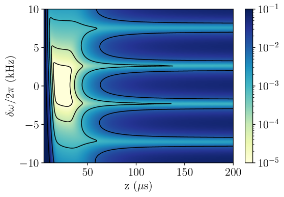
Because the gate parameters , , and depend on the specific distribution of motional modes, we provide a concrete example of optimal parameter selection for the model of a three-ion chain described in section II.5, which targets the outer ions and the lowest two radial modes. To determine the optimal gate parameters and assess their robustness for this model, we numerically vary the Gaussian width for a fixed pulse duration of s and show the performance of the gate over a range of kHz in Fig. 2. At large values of in this plot, the pulse resembles a square pulse with an approximately constant magnitude during the gate and a strong truncation effect. In this regime, we recover an infidelity proportional to , as we expect for the Fourier transform of a square pulse. Toward the lower end of on the plot, the pulse resembles a Gaussian with a small truncation effect, and we find that there is a broad region of and where the gate performs well. For example, the state infidelity remains below over the range: kHz kHz for s and over the range: s s for .
III.2 Experimental Implementation
We implement the derived gate on a chain of 171Yb+ ions to measure robustness to symmetric detuning offsets. We use the hyperfine ground, “clock” states as the qubit levels: and . In all experiments, all ions are initialized in and the gate under study is applied to two target ions. A global, single-qubit rotation is then applied in parity scan measurements (described in III.3). Finally, in all measurements, the population of each qubit state is determined by fluorescence detection. The relevant two-ion state is labelled as where and are the states of the two target ions, and is the state of the third “spectator” ion in the chain, which is ignored.
We set the principal axes of the trap to be at a 45 angle from the effective Raman -vector to allow for Raman sideband cooling on all radial modes, and thus observe a total of radial motional frequencies. For the fidelity measurements presented here, we have radial motional frequencies of MHz and MHz, and an axial center-of-mass frequency of 0.52 MHz. As modelled previously, we operate between the lowest two radial-b modes.
The Gaussian pulse shape is approximated by a natural cubic spline with 13 amplitude knots that are passed to our custom Radio Frequency System-on-Chip (RFSoC) hardware, “Octet” [24]. Octet generates the RF waveform that drives the acousto-optic modulators (AOMs) which perform the required RF to optical transduction. The spline knots are equally spaced along the square root of a Gaussian pulse shape and applied to both the individual addressing beams and counterpropagating global beam AOMs, thus producing a Gaussian temporal profile in the two-photon Raman Rabi rate of the pulse. The first and last knots of the spline are non-zero, and truncate parts of the infinite Gaussian lying outside of the pulse duration.
We choose to implement a gate with on the experiment to maintain reasonably low truncation error while still avoiding demanding Rabi rates. A gate time of 200 s is chosen empirically to minimize the effects of heating, truncation, and Fourier broadening. The “balance point” detuning () is found by scanning the symmetric detuning and finding the point of zero slope in the population, and the peak Rabi rate () is set by varying the scaling of the Gaussian pulse shape and finding the point of equal and populations. For the balanced Gaussian gate demonstrated here, kHz and kHz.
Although the wavelength (355 nm) of the Raman laser is chosen to approximately balance the AC Stark Shift on the qubit transition, there remains a residual differential AC Stark Shift on the order of 1 kHz. To compensate for this shift, we dynamically apply a virtual frame rotation at a rate proportional to the intensity of the laser applied to each ion. The magnitude of the frame rotation is found by preparing in the state, applying two MS gates back to back, and maximizing the resultant population in the state.
III.3 Experimental Results
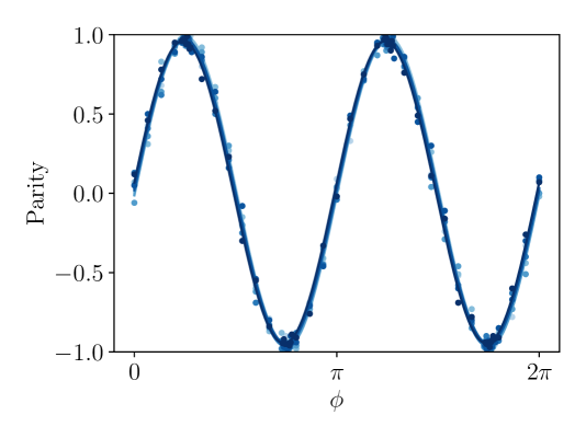
We measure the performance of the balanced Gaussian MS gate and compare it to the unbalanced Gaussian MS gates. While our heating rate is high and ultimate fidelity of both gates appears to be dominated by incoherent heating errors, there is clear difference in response to intentionally applied symmetric detuning offsets. At several points in the measured range of detuning offsets, we measure both the even parity population after an MS gate and the amplitude of a parity oscillation acquired by applying a single-qubit pulse with variable phase after the MS gate. We then estimate the fidelity () according to [28, 29, 30, 31],
| (14) |
where is the population of the state after the MS gate and is the amplitude of the parity oscillation.
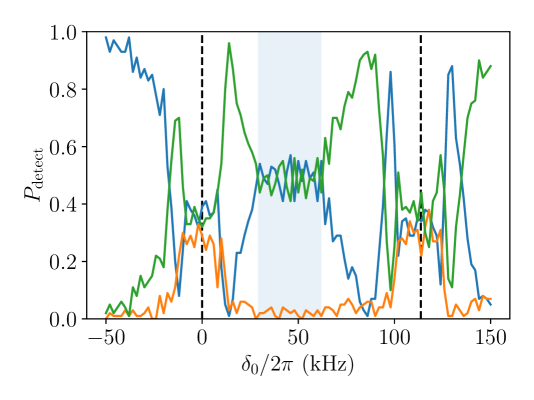
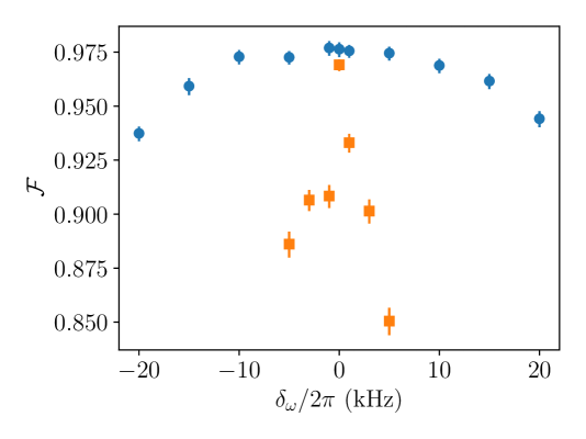
We apply the gate to the outer two ions on a three-ion chain, operating between the zig-zag and tilt modes and characterize its performance, as presented in Fig. 3. In a scan of the symmetric detuning offset, we prepare the ions in , the gate is applied, and the populations are read out. The even parity populations serve as an indicator for gate angle, and show the correct gate angle is achieved in a range of 20 kHz centered around kHz relative to the zig-zag mode, when . The odd parity population () is an indicator of displacement error, and shows good performance (population is near zero) as long as the detuning is sufficiently far from the motional modes. We then estimate the fidelity of the gate at various symmetric detuning offsets by taking a parity curve and a population measurement with 4000 shots at each detuning. We find that the fidelity of the balanced Gaussian MS gate drops by < 1% over kHz, indicating broad robustness to symmetric detuning offset. By contrast, the fidelity of an unbalanced Gaussian gate (operated below the lowest mode, kHz 111The laser power required to perform the unbalanced Gaussian MS gate is significantly higher since there is only strong contribution from one motional mode instead of two. As such, we are limited to a detuning of -25.3 kHz to stay within the bounds of our laser system. We also use the center ion and an edge ion in the unbalanced case to take advantage of the stronger zig-zag coupling from the center ion.) drops by > 3% even from an offset of kHz. While the peak fidelity of the balanced Gaussian is only 97.7%, we currently have relatively high heating rates (1000s of quanta/s) compared to contemporary systems [33, 34], and we believe that our peak fidelity is limited mostly by incoherent heating errors.
III.4 Extension to Larger Numbers of Ions
In addition to numerically and experimentally verifying performance of the balanced Gaussian gate on a chain of three ions, we also numerically explore the simulated MS gate performance on chains of variable length from up to . As described in section III.1, we target the lowest two motional modes ( and ) of the -ion chain because we expect to achieve more robustness to frequency error by targeting the neighboring modes with the largest frequency splitting. In the region between these modes, we will find a detuning that solves equation (13) and balances the contributions to from all modes, which is possible when the products and have opposite signs.
To maintain consistency in the sign and magnitude of the Lamb-Dicke parameters between chains of different , we target the ions to the immediate left and right of center, for which we find a solution to equation (13) in each case. The targeted ions are the two center ions of the chain for even and the center ion and one of its neighbors for odd . For this choice of ions, targeting the lowest two modes leads to a balanced gate with a value of that solves equation (13); however, has the opposite sign for even than for odd . To maintain the same value of the target propagator (and hence the same target gate) in our simulations for both even and odd , we impose a differential laser phase of between the two ions for even . We model this change in phase by , which modifies the handedness of the phase-space trajectories and has the same effect on as .
As grows, we relax the axial frequency of the harmonic potential such that at all , the separation between the equilibrium positions of the two center ions (the center ion and its neighbors) for even (odd) is a fixed value. We call this quantity the center ion separation parameter, . We make this choice to keep a fixed center ion separation parameter at the expense of varying axial frequency in order to maintain consistency with an experimental apparatus designed for a fixed individual addressing beam separation. This choice comes at the cost of an increasingly dense radial motional mode sideband spectrum as grows because the spacing of the radial modes is set by the ratio of the axial to radial trap frequencies. We also note that at any particular , the separation of ions will increase from center to edge of the chain, as we model a simple harmonic potential in the axial direction. While anharmonic potentials have been considered in other works to keep spacing constant within a chain [35, 36, 37], we deem the implementation of a non-harmonic potential to be outside the scope of this investigation. We also use the same values of s and s for each and .
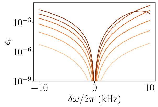
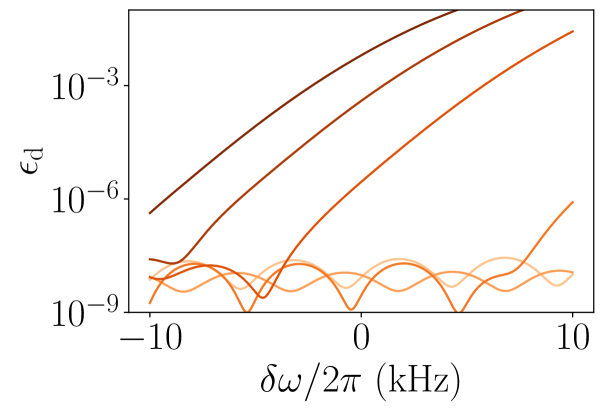

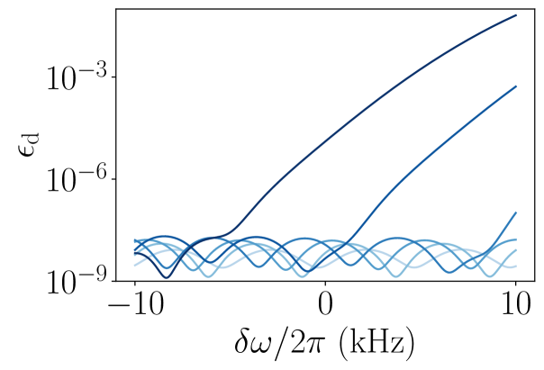
Figure 4 shows the contributions and to the state infidelity over an experimentally relevant range of frequency errors for ion chains of length to with m. Here, we have reduced the value of from the previous sections to achieve frequency-robust gates for all . We can see that the robustness to generally decreases with increasing , but the gate error has a slightly different dependence on for even and odd . This difference comes from the Lamb-Dicke parameters of the lowest two modes for each chain, which cause the value of that solves equation (13) to lie much closer to the second lowest mode () for even than for odd . We can see that while the robustness of is approximately equal for similar length chains of even and odd , the smaller value of for even causes over this range of to be dramatically larger than for odd .
Figure 4 also shows that strongly dominates when (for even ) and when (for odd ). For greater than these values, becomes small enough that makes a significant contribution to . Consequently, although is minimized at , the minimum of vs. is shifted away from as is increased. This effect is consistent with our gate design since we chose to maximize the robustness of with respect to instead of minimizing . Although the sensitivity to frequency error grows with increasing , the balanced Gaussian gate achieves a remarkable robustness to frequency error with remaining below the level for kHz for ion chains of length to 33.
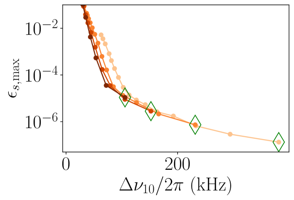
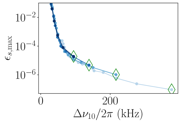
To quantify the sensitivity to frequency error for each length of chain, we compute the maximum state infidelity over a kHz range from the frequency that minimizes . Figure 5 shows this measure of sensitivity for even and odd , separately, and for m to m. For both even and odd , is approximately a function of only the splitting between the lowest two modes for each value of , despite the different motional frequencies, Lamb-Dicke parameters, number of ions , and pulse shape parameters and . Since appears to be a good predictor of balanced Gaussian gate performance for the chains considered in this work, we note that designs of new experiments intending to implement these gates should consider the mode spacing when choosing a value of and . The value of decreases monotonically with larger (for fixed ) and increases for smaller (at fixed ).
The approximate correspondence between and arises because is often dominated by the contribution from for the chains we have considered. When dominates, the sensitivity depends strongly on the magnitude of at , which is set by . This approximate correspondence breaks down when becomes significant, as is set by the detuning instead of . In such scenarios, can be substantially different for chains with different but the same . For example, for m, the lightest curves in Fig. 5, we find increased for long chains (low ) as compared to chains with m to m for the same values of . This effect is much more pronounced for even than for odd , consistent with the greater contribution from for even .
In this extension to larger , we have reduced the ion separation parameter from our experimental implementation for to increase and improve the performance of MS gates at experimentally relevant frequency errors for large . Although this improves the robustness of our simulated gates, a reduction in could have detrimental effects on quantum circuit performance that are not included in our simulations by, for example, increasing the level of crosstalk between neighboring qubits [38]. However, there has been promising research on applying spin-echo pulses to cancel out the effects of crosstalk when individual ions cannot be perfectly resolved [39]. Alternatively, one could decrease the radial trap frequency to increase , but one needs to balance this increased robustness to frequency noise with the additional amount of anomalous heating experienced by lower frequency motional modes.
IV Conclusion and Outlook
In summary, we have designed an MS gate that shows broad robustness to motional frequency errors, addressing a key error mechanism in trapped ion entangling gates. Further, our gate is performed with a simple analytic pulse shape, and therefore requires little in the way of computational overhead and technical complexity. In conjunction with this low cost, the prospects for scaling to a larger number of ions present a promising outlook for implementation of this gate on contemporary and next generation trapped ion systems.
V Acknowledgments
This research was supported by the U.S. Department of Energy, Office of Science, Office of Advanced Scientific Computing Research Quantum Testbed Program. Sandia National Laboratories is a multimission laboratory managed and operated by National Technology & Engineering Solutions of Sandia, LLC, a wholly owned subsidiary of Honeywell International Inc., for the U.S. Department of Energy’s National Nuclear Security Administration under contract DE-NA0003525. This paper describes objective technical results and analysis. Any subjective views or opinions that might be expressed in the paper do not necessarily represent the views of the U.S. Department of Energy or the United States Government.
B.P.R. and M.N.H.C. contributed equally to this work.
References
- Sørensen and Mølmer [2000] A. Sørensen and K. Mølmer, Phys. Rev. A 62, 022311 (2000).
- Ballance et al. [2016] C. J. Ballance, T. P. Harty, N. M. Linke, M. A. Sepiol, and D. M. Lucas, Phys. Rev. Lett. 117, 060504 (2016).
- Gaebler et al. [2016] J. P. Gaebler, T. R. Tan, Y. Lin, Y. Wan, R. Bowler, A. C. Keith, S. Glancy, K. Coakley, E. Knill, D. Leibfried, and D. J. Wineland, Phys. Rev. Lett. 117, 060505 (2016).
- Lanyon et al. [2011] B. P. Lanyon, C. Hempel, D. Nigg, M. Müller, R. Gerritsma, F. Zähringer, P. Schindler, J. T. Barreiro, M. Rambach, G. Kirchmair, M. Hennrich, P. Zoller, R. Blatt, and C. F. Roos, Science 334, 57 (2011).
- Shor [1995] P. W. Shor, Phys. Rev. A 52, R2493 (1995).
- Kitaev [2003] A. Kitaev, Annals of Physics 303, 2 (2003).
- Aharonov and Ben-Or [2008] D. Aharonov and M. Ben-Or, SIAM Journal on Computing 38, 1207 (2008).
- Debnath et al. [2016] S. Debnath, N. M. Linke, C. Figgatt, K. A. Landsman, K. Wright, and C. Monroe, Nature 536, 63 (2016).
- Wright et al. [2019] K. Wright, K. M. Beck, S. Debnath, J. M. Amini, Y. Nam, N. Grzesiak, J.-S. Chen, N. C. Pisenti, M. Chmielewski, C. Collins, K. M. Hudek, J. Mizrahi, J. D. Wong-Campos, S. Allen, J. Apisdorf, P. Solomon, M. Williams, A. M. Ducore, A. Blinov, S. M. Kreikemeier, V. Chaplin, M. Keesan, C. Monroe, and J. Kim, Nature Communications 10, 5464 (2019).
- Zhu et al. [2006] S.-L. Zhu, C. Monroe, and L.-M. Duan, Europhysics Letters (EPL) 73, 485 (2006).
- Roos [2008] C. F. Roos, New Journal of Physics 10, 013002 (2008).
- Benhelm et al. [2008] J. Benhelm, G. Kirchmair, C. F. Roos, and R. Blatt, Nature Physics 4, 463 (2008).
- Choi et al. [2014] T. Choi, S. Debnath, T. A. Manning, C. Figgatt, Z.-X. Gong, L.-M. Duan, and C. Monroe, Phys. Rev. Lett. 112, 190502 (2014).
- Tinkey et al. [2022] H. N. Tinkey, C. R. Clark, B. C. Sawyer, and K. R. Brown, Phys. Rev. Lett. 128, 050502 (2022).
- Leung et al. [2018] P. H. Leung, K. A. Landsman, C. Figgatt, N. M. Linke, C. Monroe, and K. R. Brown, Phys. Rev. Lett. 120, 020501 (2018).
- Wang et al. [2020] Y. Wang, S. Crain, C. Fang, B. Zhang, S. Huang, Q. Liang, P. H. Leung, K. R. Brown, and J. Kim, Phys. Rev. Lett. 125, 150505 (2020).
- Leung and Brown [2018] P. H. Leung and K. R. Brown, Phys. Rev. A 98, 032318 (2018).
- Landsman et al. [2019] K. A. Landsman, Y. Wu, P. H. Leung, D. Zhu, N. M. Linke, K. R. Brown, L. Duan, and C. Monroe, Phys. Rev. A 100, 022332 (2019).
- Green and Biercuk [2015] T. J. Green and M. J. Biercuk, Phys. Rev. Lett. 114, 120502 (2015).
- Lu et al. [2019] Y. Lu, S. Zhang, K. Zhang, W. Chen, Y. Shen, J. Zhang, J.-N. Zhang, and K. Kim, Nature 572, 363 (2019).
- Milne et al. [2020] A. R. Milne, C. L. Edmunds, C. Hempel, F. Roy, S. Mavadia, and M. J. Biercuk, Phys. Rev. Applied 13, 024022 (2020).
- Kang et al. [2021] M. Kang, Q. Liang, B. Zhang, S. Huang, Y. Wang, C. Fang, J. Kim, and K. R. Brown, Phys. Rev. Applied 16, 024039 (2021).
- Iverson and Preskill [2020] J. K. Iverson and J. Preskill, New Journal of Physics 22, 073066 (2020).
- Clark et al. [2021] S. M. Clark, D. Lobser, M. C. Revelle, C. G. Yale, D. Bossert, A. D. Burch, M. N. Chow, C. W. Hogle, M. Ivory, J. Pehr, B. Salzbrenner, D. Stick, W. Sweatt, J. M. Wilson, E. Winrow, and P. Maunz, IEEE Transactions on Quantum Engineering 2, 1 (2021).
- Ruzic et al. [2022] B. P. Ruzic, T. A. Barrick, J. D. Hunker, R. J. Law, B. K. McFarland, H. J. McGuinness, L. P. Parazzoli, J. D. Sterk, J. W. Van Der Wall, and D. Stick, Phys. Rev. A 105, 052409 (2022).
- Bruzewicz et al. [2015] C. D. Bruzewicz, J. M. Sage, and J. Chiaverini, Phys. Rev. A 91, 041402 (2015).
- Boldin et al. [2018] I. A. Boldin, A. Kraft, and C. Wunderlich, Phys. Rev. Lett. 120, 023201 (2018).
- Sackett et al. [2000] C. A. Sackett, D. Kielpinski, B. E. King, C. Langer, V. Meyer, C. J. Myatt, M. Rowe, Q. A. Turchette, W. M. Itano, D. J. Wineland, and C. Monroe, Nature 404, 256 (2000).
- Kim et al. [2009] K. Kim, M.-S. Chang, R. Islam, S. Korenblit, L.-M. Duan, and C. Monroe, Phys. Rev. Lett. 103, 120502 (2009).
- Manning [2014] T. A. Manning, Quantum Information Processing with Trapped Ion Chains, Ph.D. thesis, University of Maryland, College Park (2014).
- Figgatt et al. [2019] C. Figgatt, A. Ostrander, N. M. Linke, K. A. Landsman, D. Zhu, D. Maslov, and C. Monroe, Nature 572, 368 (2019).
- Note [1] The laser power required to perform the unbalanced Gaussian MS gate is significantly higher since there is only strong contribution from one motional mode instead of two. As such, we are limited to a detuning of -25.3 kHz to stay within the bounds of our laser system. We also use the center ion and an edge ion in the unbalanced case to take advantage of the stronger zig-zag coupling from the center ion.
- Egan [2021] L. N. Egan, Scaling Quantum Computers with Long Chains of Trapped Ions, Ph.D. thesis, University of Maryland, College Park (2021).
- Brown et al. [2021] K. R. Brown, J. Chiaverini, J. M. Sage, and H. Häffner, Nature Reviews Materials 6, 892 (2021).
- Lin et al. [2009] G.-D. Lin, S.-L. Zhu, R. Islam, K. Kim, M.-S. Chang, S. Korenblit, C. Monroe, and L.-M. Duan, EPL (Europhysics Letters) 86, 60004 (2009).
- Johanning [2016] M. Johanning, Applied Physics B 122, 71 (2016).
- Xie et al. [2017] Y. Xie, X. Zhang, B. Ou, T. Chen, J. Zhang, C. Wu, W. Wu, and P. Chen, Phys. Rev. A 95, 032341 (2017).
- Crain et al. [2014] S. Crain, E. Mount, S. Baek, and J. Kim, Applied Physics Letters 105, 181115 (2014).
- Fang et al. [2022] C. Fang, Y. Wang, S. Huang, K. R. Brown, and J. Kim, arXiv 10.48550/ARXIV.2206.02703 (2022).