Energy-Efficient Cell-Free Network
Assisted by Hybrid RISs

Wanting Lyu, Yue Xiu, Songjie Yang, Chau Yuen, , and Zhongpei Zhang Wanting Lyu, Yue Xiu, Songjie Yang and Zhongpei Zhang are with National Key Laboratory of Science and Technology on Communications, University of Electronic Science and Technology of China, Chengdu61173, China (E-mail: lyuwanting@yeah.net; xiuyue12345678@163.com; yangsongjie@std.uestc.edu.cn; zhangzp@uestc.edu.cn). C. Yuen is with the Engineering Product Development (EPD) Pillar, Singapore University of Technology and Design, Singapore 487372 (e-mail: yuenchau@sutd.edu.sg).
Abstract

In this letter, we investigate a cell-free network aided by hybrid reconfigurable intelligent surfaces (RISs), which consists of a mixture of passive and active elements that are capable of amplifying and reflecting the incident signal. To maximize the energy efficiency (EE) of the system, we formulate a joint transmit beamforming and RIS coefficients optimization problem. To deal with the fractional objective function, Dinkelbach transform, Lagrangian dual reformulation, and quadratic transform are utilized, with a block coordinate descent (BCD) based algorithm proposed to decouple the variables. In addition, successive convex approximation (SCA) method is applied to iteratively to tackle the non-convexity of the sub-problems. Simulation results illustrate the effectiveness and convergence of the proposed algorithm through analyzing the EE and sum rate performance with varying parameter settings. The proposed hybrid RISs schemes can achieve 92%percent9292\% of the sum rate but 188%percent188188\% of EE of active RISs schemes. As compared with passive RISs, 11%percent1111\% gain in sum rate can be achieved with comparable EE.

Index Terms:
Beamforming, cell-free, convex optimization, energy efficiency, reconfigurable intelligent surfaces.

I Introduction

Cell-free network has gained great attractiveness in beyond fifth-generation mobile communications (B5G) without cell boundaries [5]. It has great potential in next generation indoor and hot-spot environment, such as shopping malls, train stations, hospitals and subways. In addition, cell-free network is particularly effective in high-mobility scenarios like vehicular networks without handover cost [7]. Despite the above advantages, conventional cell-free network requires massive access points (APs), resulting in high power consumption both for AP transmit power and hardware power [8].

Recently, reconfigurable intelligent surface (RIS), as a promising technology to overcome obstacles, enhance channel capacity and improve energy efficiency [33] in various scenarios [29, 26, 27, 30, 31, 32, 34], has been integrated into cell-free networks to replace some of the APs [8][18][2]. However, the ideal capacity gains provided by RIS is difficult to achieve practically owing to the ”multiplicative fading” effect caused by RIS, causing extremely large path loss in the cascaded channels. Considering this, a new structure of RIS, namely active RIS has been proposed by authors of [11][12], where active reflecting elements are configured with radio frequency (RF) chains and power amplifiers to alleviate the severe fading effect. The active RIS, however, requires higher power consumption, and introduce non-negligible self-interference and thermal noise. Considering the trade-off between the signal amplifying effect and power consumption, a hybrid RIS architecture has been proposed [14]. In this architecture, only a few reflecting elements are activated, introducing a lower level of transmit power and effective noise than active RIS, while significantly enhancing the signal strength compared with full RIS. Hybrid RIS provides a reliable, sustainable solution to the wireless network design with an acceptable level of cost and power consumption.

To the best of our knowledge, conventional passive RISs have been used in cell-free networks to reduce the power consumption, but the data rate is limited by the severe double-fading effect. To improve the energy efficiency (EE) of cell-free networks while alleviating the fading effect, we consider hybrid RISs with a few active elements capable of amplifying the incident signal to replace a part of APs. Thus, we consider a downlink cell-free network assisted by hybrid RISs to achieve a trade-off between EE and sum rate performance. A highly coupled non-convex EE maximization problem constraint on the minimum rate requirement is formulated by optimizing the digital beamforming and hybrid RIS coefficients design. Then, we propose a block coordinate descent (BCD) based algorithm to decouple the variables. To deal with the fractional objective function, Dinkelbach method, Lagrangian dual reformulation, and quadratic transform are applied. Particularly, successive convex approximation (SCA) method is used to tackle the non-convexity of the subproblems. Simulation results show the effectiveness of the proposed algorithm in terms of improving energy efficiency.
Refer to caption
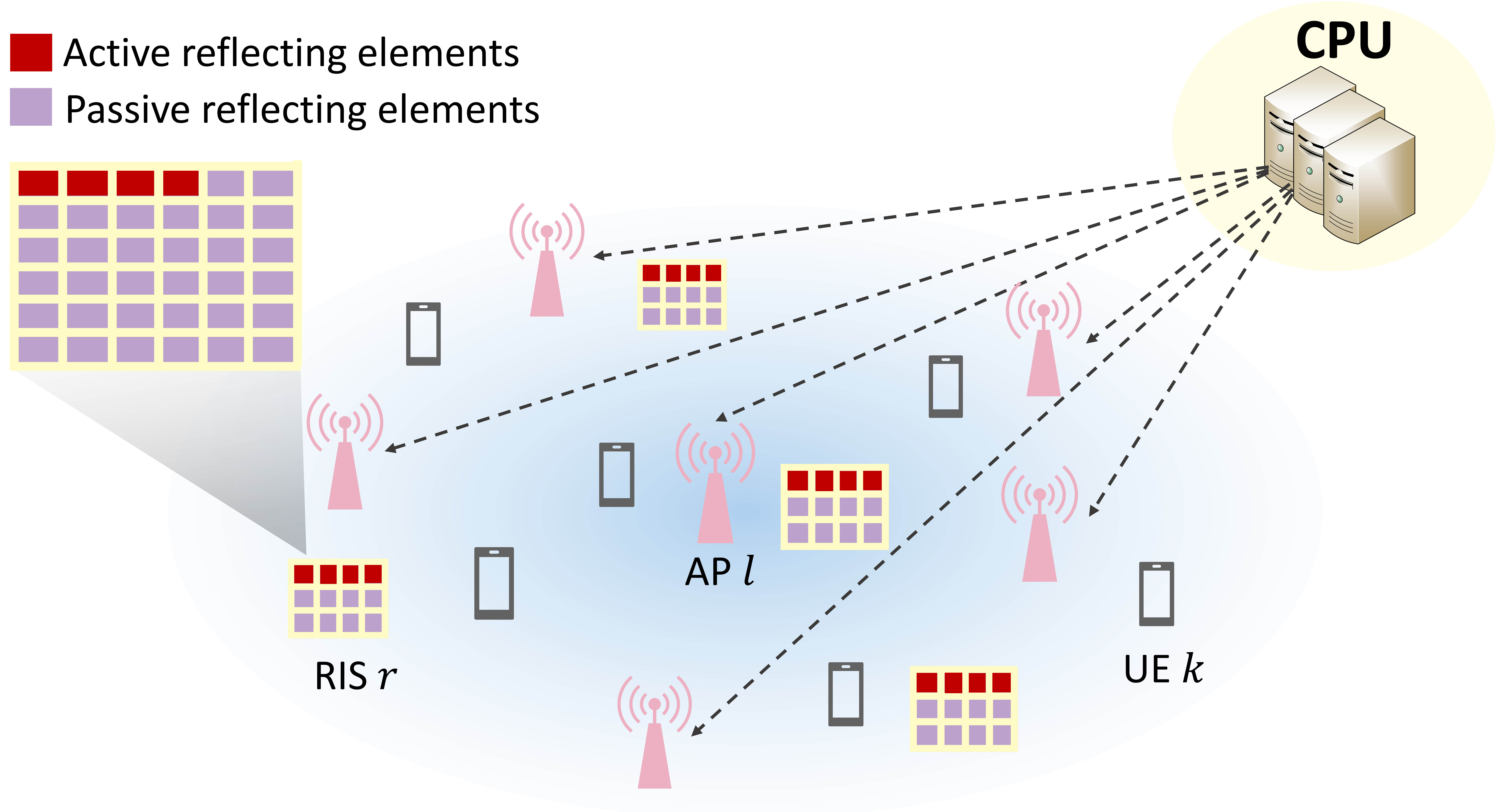
Figure 1: System model of the hybrid RIS-aided cell-free network.

II System Model and Problem Formulation

II-A Transmission Model

Consider a downlink cell-free network with L𝐿L APs each configured with Ntsubscript𝑁𝑡N_{t} antennas serving K𝐾K single-antenna users as shown in Fig. 1. To enhance the communication quality and improve the energy efficiency, R𝑅R hybrid RISs are deployed in the network, each with Nssubscript𝑁𝑠N_{s} reflecting elements. For each RIS, NaNsmuch-less-thansubscript𝑁𝑎subscript𝑁𝑠N_{a}\ll N_{s} active reflecting elements are predetermined in the set 𝒜rsubscript𝒜𝑟\mathcal{A}_{r}, where |𝒜r|=Nasubscript𝒜𝑟subscript𝑁𝑎|\mathcal{A}_{r}|=N_{a}. The RIS coefficient matrix of RIS r𝑟r is defined as 𝚯r=diag{ar,1,,ar,Ns}subscript𝚯𝑟diagsubscript𝑎𝑟1subscript𝑎𝑟subscript𝑁𝑠\mathbf{\Theta}_{r}=\text{diag}\{a_{r,1},\dots,a_{r,N_{s}}\}, where ar,ns=|ar,ns|ejθr,nssubscript𝑎𝑟subscript𝑛𝑠subscript𝑎𝑟subscript𝑛𝑠superscript𝑒𝑗subscript𝜃𝑟subscript𝑛𝑠a_{r,n_{s}}=|a_{r,n_{s}}|e^{j\theta_{r,n_{s}}} denotes the coefficient of the nsthsuperscriptsubscript𝑛𝑠𝑡n_{s}^{th} element, with the amplitude |ar,ns|amaxsubscript𝑎𝑟subscript𝑛𝑠subscript𝑎𝑚𝑎𝑥|a_{r,n_{s}}|\leq a_{max} if the element (r,ns)𝑟subscript𝑛𝑠(r,n_{s}) is in the set 𝒜rsubscript𝒜𝑟\mathcal{A}_{r}, and |ar,ns|1subscript𝑎𝑟subscript𝑛𝑠1|a_{r,n_{s}}|\leq 1 otherwise. To combine the elements in all R𝑅R RISs together and for ease of exposition, define n=Ns(r1)+ns,1nNformulae-sequence𝑛subscript𝑁𝑠𝑟1subscript𝑛𝑠1𝑛𝑁n=N_{s}(r-1)+n_{s},1\leq n\leq N, where N=RNs𝑁𝑅subscript𝑁𝑠N=RN_{s}. The elements in set 𝒜=r𝒜r𝒜subscript𝑟subscript𝒜𝑟\mathcal{A}=\mathop{\cup}\limits_{r}\mathcal{A}_{r} are the active reflecting elements in all R𝑅R RISs. Then, the overall RIS matrix can be written as 𝚯=blockdiag{𝚯1,,𝚯R}𝚯blockdiagsubscript𝚯1subscript𝚯𝑅\mathbf{\Theta}=\text{blockdiag}\{\mathbf{\Theta}_{1},\dots,\mathbf{\Theta}_{R}\}. To distinguish the active and passive elements, rewrite 𝚯𝚯\mathbf{\Theta} as 𝚯=𝚿+𝚼𝚯𝚿𝚼\mathbf{\Theta}=\mathbf{\Psi}+\mathbf{\Upsilon}, where 𝚿=𝐀𝚯𝚿𝐀𝚯\mathbf{\Psi}=\mathbf{A}\mathbf{\Theta} and 𝚼=(𝐈N𝐀)𝚯𝚼subscript𝐈𝑁𝐀𝚯\mathbf{\Upsilon}=(\mathbf{I}_{N}-\mathbf{A})\mathbf{\Theta} denote the coefficient matrices of active and passive elements, respectively, where the selection matrix 𝐀𝐀\mathbf{A} is an N×N𝑁𝑁N\times N diagonal matrix with the elements corresponding to set 𝒜𝒜\mathcal{A} to be 111, and others to be 00.

Assume that all APs and all RISs serve all users over the same time-frequency resource, such that data symbol 𝐬K×1𝐬superscript𝐾1\mathbf{s}\in\mathbb{C}^{K\times 1} satisfying 𝔼{𝐬𝐬H}=𝐈K𝔼superscript𝐬𝐬𝐻subscript𝐈𝐾\mathbb{E}\{\mathbf{ss}^{H}\}=\mathbf{I}_{K} is transmitted from the APs simultaneously. A central processing unit (CPU) connected to all APs generates the digital beamformers based on perfectly known channel state information (CSI) of all the links. The transmitted signal at the AP l𝑙l can then be expressed as 𝐱l=𝐖l𝐬subscript𝐱𝑙subscript𝐖𝑙𝐬\mathbf{x}_{l}=\mathbf{W}_{l}\mathbf{s}, where 𝐖lNt×Ksubscript𝐖𝑙superscriptsubscript𝑁𝑡𝐾\mathbf{W}_{l}\in\mathbb{C}^{N_{t}\times K} denotes the transmit beamforming matrix at AP l𝑙l. The links from AP l𝑙l to user k𝑘k, from AP l𝑙l to RIS r𝑟r, and from RIS r𝑟r to user k𝑘k are denoted as 𝐝l,kH1×Ntsuperscriptsubscript𝐝𝑙𝑘𝐻superscript1subscript𝑁𝑡\mathbf{d}_{l,k}^{H}\in\mathbb{C}^{1\times N_{t}}, 𝐆l,rNs×Nt and 𝐟r,kH1×Nssubscript𝐆𝑙𝑟superscriptsubscript𝑁𝑠subscript𝑁𝑡 and superscriptsubscript𝐟𝑟𝑘𝐻superscript1subscript𝑁𝑠\mathbf{G}_{l,r}\in\mathbb{C}^{N_{s}\times N_{t}}\text{ and }\mathbf{f}_{r,k}^{H}\in\mathbb{C}^{1\times N_{s}}, respectively. Thus, the received signal of user k𝑘k can be expressed as

yk=l=1L(𝐝l,kH+r=1R𝐟r,kH𝚯r𝐆l,r)𝐖l𝐬+r=1R𝐟r,kH𝚿𝐳r+nk,subscript𝑦𝑘superscriptsubscript𝑙1𝐿superscriptsubscript𝐝𝑙𝑘𝐻superscriptsubscript𝑟1𝑅superscriptsubscript𝐟𝑟𝑘𝐻subscript𝚯𝑟subscript𝐆𝑙𝑟subscript𝐖𝑙𝐬superscriptsubscript𝑟1𝑅superscriptsubscript𝐟𝑟𝑘𝐻𝚿subscript𝐳𝑟subscript𝑛𝑘y_{k}=\sum_{l=1}^{L}(\mathbf{d}_{l,k}^{H}+\sum_{r=1}^{R}\mathbf{f}_{r,k}^{H}\mathbf{\Theta}_{r}\mathbf{G}_{l,r})\mathbf{W}_{l}\mathbf{s}+\sum_{r=1}^{R}\mathbf{f}_{r,k}^{H}\mathbf{\Psi}\mathbf{z}_{r}+n_{k}, (1)

where nk𝒞𝒩(0,σ02)similar-tosubscript𝑛𝑘𝒞𝒩0superscriptsubscript𝜎02n_{k}\sim\mathcal{CN}(0,\sigma_{0}^{2}) is the additional white Gaussion noise (AWGN) at user k𝑘k, and 𝐳r𝒞𝒩(𝟎,σr2𝐀r𝐈Ns)similar-tosubscript𝐳𝑟𝒞𝒩0superscriptsubscript𝜎𝑟2subscript𝐀𝑟subscript𝐈subscript𝑁𝑠\mathbf{z}_{r}\sim\mathcal{CN}(\mathbf{0},\sigma_{r}^{2}\mathbf{A}_{r}\mathbf{I}_{N_{s}}) is the effective noise caused by the active elements of RIS r𝑟r, including the AWGN and self-interference due to the full-duplex mode. Or we can write (1) in a more compact form as

yk=(𝐝kH+𝐟kH𝚯𝐆)𝐖𝐬+𝐟kH𝚿𝐳+nk,=𝐡~kH𝐖𝐬+𝐟kH𝚿𝐳+nk,\begin{split}y_{k}&=(\mathbf{d}_{k}^{H}+\mathbf{f}_{k}^{H}\mathbf{\Theta G})\mathbf{Ws}+\mathbf{f}_{k}^{H}\mathbf{\Psi z}+n_{k},\\ &=\tilde{\mathbf{h}}_{k}^{H}\mathbf{Ws}+\mathbf{f}_{k}^{H}\mathbf{\Psi z}+n_{k},\end{split} (2)

where 𝐝kH=(𝐝1,kH,,𝐝L,kH)1×LNtsuperscriptsubscript𝐝𝑘𝐻superscriptsubscript𝐝1𝑘𝐻superscriptsubscript𝐝𝐿𝑘𝐻superscript1𝐿subscript𝑁𝑡\mathbf{d}_{k}^{H}=(\mathbf{d}_{1,k}^{H},\dots,\mathbf{d}_{L,k}^{H})\in\mathbb{C}^{1\times LN_{t}}, 𝐟kH=(𝐟1,kH,,𝐟R,kH)1×RNssuperscriptsubscript𝐟𝑘𝐻superscriptsubscript𝐟1𝑘𝐻superscriptsubscript𝐟𝑅𝑘𝐻superscript1𝑅subscript𝑁𝑠\mathbf{f}_{k}^{H}=(\mathbf{f}_{1,k}^{H},\dots,\mathbf{f}_{R,k}^{H})\in\mathbb{C}^{1\times RN_{s}}, 𝐖=(𝐖1T,,𝐖LT)TLNt×K𝐖superscriptsuperscriptsubscript𝐖1𝑇superscriptsubscript𝐖𝐿𝑇𝑇superscript𝐿subscript𝑁𝑡𝐾\mathbf{W}=(\mathbf{W}_{1}^{T},\dots,\mathbf{W}_{L}^{T})^{T}\in\mathbb{C}^{LN_{t}\times K}, 𝐳=(𝐳1,,𝐳R)RNs×1𝐳subscript𝐳1subscript𝐳𝑅superscript𝑅subscript𝑁𝑠1\mathbf{z}=(\mathbf{z}_{1},\dots,\mathbf{z}_{R})\in\mathbb{C}^{RN_{s}\times 1}, and

𝐆=(𝐆1,1𝐆L,1𝐆1,R𝐆L,R)RNs×LNt.𝐆matrixsubscript𝐆11subscript𝐆𝐿1subscript𝐆1𝑅subscript𝐆𝐿𝑅superscript𝑅subscript𝑁𝑠𝐿subscript𝑁𝑡\mathbf{G}=\begin{pmatrix}\mathbf{G}_{1,1}&\cdots&\mathbf{G}_{L,1}\\ \vdots&\ddots&\vdots\\ \mathbf{G}_{1,R}&\cdots&\mathbf{G}_{L,R}\end{pmatrix}\in\mathbb{C}^{RN_{s}\times LN_{t}}. (3)

Hence, the received signal-to-interference-plus-noise (SINR) at user k𝑘k can be expressed as

γk=|𝐡~kH𝐰k|2jk|𝐡~kH𝐰j|2+r=1Rσ~r2+σ02,subscript𝛾𝑘superscriptsuperscriptsubscript~𝐡𝑘𝐻subscript𝐰𝑘2subscript𝑗𝑘superscriptsuperscriptsubscript~𝐡𝑘𝐻subscript𝐰𝑗2superscriptsubscript𝑟1𝑅superscriptsubscript~𝜎𝑟2superscriptsubscript𝜎02\gamma_{k}=\frac{|\tilde{\mathbf{h}}_{k}^{H}\mathbf{w}_{k}|^{2}}{\sum_{j\neq k}|\tilde{\mathbf{h}}_{k}^{H}\mathbf{w}_{j}|^{2}+\sum_{r=1}^{R}\tilde{\sigma}_{r}^{2}+\sigma_{0}^{2}}, (4)

where 𝐰ksubscript𝐰𝑘\mathbf{w}_{k} is kthsuperscript𝑘𝑡k^{th} column of the digital beamforming matrix 𝐖𝐖\mathbf{W}, and σ~r2=σr2𝐟r,kH𝚿r2superscriptsubscript~𝜎𝑟2superscriptsubscript𝜎𝑟2superscriptnormsuperscriptsubscript𝐟𝑟𝑘𝐻subscript𝚿𝑟2\tilde{\sigma}_{r}^{2}=\sigma_{r}^{2}||\mathbf{f}_{r,k}^{H}\mathbf{\Psi}_{r}||^{2} is the effective RIS noise power.

II-B Energy Efficiency

The total power consumption includes transmit power at APs, transmit power at active elements of RISs and hardware circuit power. Therefore, the total power consumption of the cell-free system can be expressed as

Ptot(𝐖,𝚿)subscript𝑃𝑡𝑜𝑡𝐖𝚿\displaystyle P_{tot}(\mathbf{W},\mathbf{\Psi}) =l=1LPl,txA(𝐖l)transmit power of APs+r=1RPr,aR(𝚿r,𝐖)transmit power of active RIS elementsabsentsubscriptsuperscriptsubscript𝑙1𝐿superscriptsubscript𝑃𝑙𝑡𝑥𝐴subscript𝐖𝑙transmit power of APssubscriptsuperscriptsubscript𝑟1𝑅superscriptsubscript𝑃𝑟𝑎𝑅subscript𝚿𝑟𝐖transmit power of active RIS elements\displaystyle=\underbrace{\sum_{l=1}^{L}P_{l,tx}^{A}(\mathbf{W}_{l})}_{\text{transmit power of APs}}+\underbrace{\sum_{r=1}^{R}P_{r,a}^{R}(\mathbf{\Psi}_{r},\mathbf{W})}_{\text{transmit power of active RIS elements}}
+l=1LPl,cA+r=1RPr,cR+k=1KPkUcircuit power of APs, RISs and UEs.subscriptsuperscriptsubscript𝑙1𝐿superscriptsubscript𝑃𝑙𝑐𝐴superscriptsubscript𝑟1𝑅superscriptsubscript𝑃𝑟𝑐𝑅superscriptsubscript𝑘1𝐾superscriptsubscript𝑃𝑘𝑈circuit power of APs, RISs and UEs\displaystyle+\underbrace{\sum_{l=1}^{L}P_{l,c}^{A}+\sum_{r=1}^{R}P_{r,c}^{R}+\sum_{k=1}^{K}P_{k}^{U}}_{\text{circuit power of APs, RISs and UEs}}. (5)

Specifically, transmit power of AP l𝑙l is Pl,txA(𝐖l)=Tr(𝐖lH𝐖l)μAsuperscriptsubscript𝑃𝑙𝑡𝑥𝐴subscript𝐖𝑙Trsuperscriptsubscript𝐖𝑙𝐻subscript𝐖𝑙superscript𝜇𝐴P_{l,tx}^{A}(\mathbf{W}_{l})=\frac{\text{Tr}(\mathbf{W}_{l}^{H}\mathbf{W}_{l})}{\mu^{A}}, and transmit power of the active elements of RIS r𝑟r is Pr,aR(𝚿r𝐖)=1μR𝔼{𝚿r(𝐆r𝐖𝐬+𝐳r)2}=1μR(Tr(𝐖H𝐆rH𝚿rH𝚿r𝐆r𝐖)+ns𝒜r|ar,ns|2σr2)superscriptsubscript𝑃𝑟𝑎𝑅subscript𝚿𝑟𝐖1superscript𝜇𝑅𝔼superscriptnormsubscript𝚿𝑟subscript𝐆𝑟𝐖𝐬subscript𝐳𝑟21superscript𝜇𝑅Trsuperscript𝐖𝐻superscriptsubscript𝐆𝑟𝐻superscriptsubscript𝚿𝑟𝐻subscript𝚿𝑟subscript𝐆𝑟𝐖subscriptsubscript𝑛𝑠subscript𝒜𝑟superscriptsubscript𝑎𝑟subscript𝑛𝑠2superscriptsubscript𝜎𝑟2P_{r,a}^{R}(\mathbf{\Psi}_{r}\mathbf{W})=\frac{1}{\mu^{R}}\mathbb{E}\{||\mathbf{\Psi}_{r}(\mathbf{G}_{r}\mathbf{W}\mathbf{s}+\mathbf{z}_{r})||^{2}\}=\frac{1}{\mu^{R}}\left(\text{Tr}(\mathbf{W}^{H}\mathbf{G}_{r}^{H}\mathbf{\Psi}_{r}^{H}\mathbf{\Psi}_{r}\mathbf{G}_{r}\mathbf{W})+\sum_{n_{s}\in\mathcal{A}_{r}}|a_{r,n_{s}}|^{2}\sigma_{r}^{2}\right), where μA,μR(0,1]superscript𝜇𝐴superscript𝜇𝑅01\mu^{A},\mu^{R}\in(0,1] denote the amplifier efficiency factors of AP and RIS, respectively.

Thus, the energy efficiency of this system can be written as

η=k=1KRkPtot,𝜂superscriptsubscript𝑘1𝐾subscript𝑅𝑘subscript𝑃𝑡𝑜𝑡\eta=\frac{\sum_{k=1}^{K}R_{k}}{P_{tot}}, (6)

where Rk=log2(1+γk)subscript𝑅𝑘subscript21subscript𝛾𝑘R_{k}=\log_{2}(1+\gamma_{k}) is the data rate of user k𝑘k.

II-C Problem Formulation

To maximize the system energy efficiency, the optimization problem can be formulated as

(P1)max𝐖,𝚯(P1)subscript𝐖𝚯\displaystyle\text{(P1)}\;\max_{\mathbf{W},\mathbf{\Theta}}\quad η𝜂\displaystyle\eta (7a)
s.t. Pl,txA(𝐖l)PmaxA,l{1,,L},formulae-sequencesuperscriptsubscript𝑃𝑙𝑡𝑥𝐴subscript𝐖𝑙superscriptsubscript𝑃𝑚𝑎𝑥𝐴for-all𝑙1𝐿\displaystyle P_{l,tx}^{A}(\mathbf{W}_{l})\leq P_{max}^{A},\;\forall l\in\{1,\dots,L\}, (7b)
0θn2π,n,formulae-sequence0subscript𝜃𝑛2𝜋for-all𝑛\displaystyle 0\leq\theta_{n}\leq 2\pi,\;\forall n, (7c)
|an|amax,n𝒜formulae-sequencesubscript𝑎𝑛subscript𝑎𝑚𝑎𝑥𝑛𝒜\displaystyle|a_{n}|\leq a_{max},\;n\in\mathcal{A} (7d)
|an|1,n𝒜formulae-sequencesubscript𝑎𝑛1𝑛𝒜\displaystyle|a_{n}|\leq 1,\;n\notin\mathcal{A} (7e)
RkRth,k,subscript𝑅𝑘subscript𝑅thfor-all𝑘\displaystyle R_{k}\geq R_{\text{th}},\;\forall k, (7f)
Pr,aR(𝚿r,𝐖)PmaxR,r,superscriptsubscript𝑃𝑟𝑎𝑅subscript𝚿𝑟𝐖superscriptsubscript𝑃𝑚𝑎𝑥𝑅for-all𝑟\displaystyle P_{r,a}^{R}(\mathbf{\Psi}_{r},\mathbf{W})\leq P_{max}^{R},\;\forall r, (7g)

where (7b), (7g) are the transmit power constraints for AP l𝑙l and RIS r𝑟r. (7c), (7d) and (7e) are the phase shift and amplitude constraints for all RIS elements, respectively. (7f)7f(\ref{Cons_rate}) is to guarantee the data rate of user k𝑘k.

However, problem (P1) is difficult to solve due to the strongly coupled variables, non-convex fractional objective function (7a), and non-convex constraints (7f). To solve this problem, we proposed an iterative BCD algorithm in section III.

III Joint Optimization Algorithm

In this section, we first transform the complex fractional objective function into equivalent concave form, and propose a BCD based algorithm to jointly optimize beamforming design 𝐖𝐖\mathbf{W} at the APs and RIS coefficients 𝚯𝚯\mathbf{\Theta} at the RISs.

We first apply Dinkelbach’s method in [19]. By introducing an auxiliary variable y^^𝑦\hat{y}, the objective function (7a) can be transformed as

f1(𝐖,𝚯,y^)=k=1Klog2(1+γk)y^Ptot(𝐖,𝚿),subscript𝑓1𝐖𝚯^𝑦superscriptsubscript𝑘1𝐾subscript21subscript𝛾𝑘^𝑦subscript𝑃𝑡𝑜𝑡𝐖𝚿f_{1}(\mathbf{W},\mathbf{\Theta},\hat{y})=\sum_{k=1}^{K}\log_{2}\left(1+\gamma_{k}\right)-\hat{y}P_{tot}(\mathbf{W},\mathbf{\Psi}), (8)

where y^^𝑦\hat{y} can be updated as

y^=k=1Klog2(1+γk)Ptot(𝐖,𝚿)superscript^𝑦superscriptsubscript𝑘1𝐾subscript21subscript𝛾𝑘subscript𝑃𝑡𝑜𝑡𝐖𝚿\hat{y}^{\prime}=\frac{\sum_{k=1}^{K}\log_{2}\left(1+\gamma_{k}\right)}{P_{tot}(\mathbf{W},\mathbf{\Psi})} (9)

in each iteration.

To further tackle the sum-logarithms in (8), Lagrangian dual reformulation in [25] is utilized, and thus f1(𝐖,𝚯,y^)subscript𝑓1𝐖𝚯^𝑦f_{1}(\mathbf{W},\mathbf{\Theta},\hat{y}) can be transformed by introducing a slack variable ϵ^=[ϵ^1,,ϵ^k]T^italic-ϵsuperscriptsubscript^italic-ϵ1subscript^italic-ϵ𝑘𝑇\hat{\mathbf{\epsilon}}=[\hat{\epsilon}_{1},...,\hat{\epsilon}_{k}]^{T}:

f2(𝐖,𝚯,y^,ϵ^)=k=1Klog(1+ϵ^k)k=1Kϵ^k+k=1K(1+ϵ^k)γk1+γk.subscript𝑓2𝐖𝚯^𝑦^italic-ϵsuperscriptsubscript𝑘1𝐾1subscript^italic-ϵ𝑘superscriptsubscript𝑘1𝐾subscript^italic-ϵ𝑘superscriptsubscript𝑘1𝐾1subscript^italic-ϵ𝑘subscript𝛾𝑘1subscript𝛾𝑘f_{2}(\mathbf{W},\mathbf{\Theta},\hat{y},\hat{\mathbf{\epsilon}})=\sum_{k=1}^{K}\log(1+\hat{\epsilon}_{k})-\sum_{k=1}^{K}\hat{\epsilon}_{k}+\sum_{k=1}^{K}\frac{(1+\hat{\epsilon}_{k})\gamma_{k}}{1+\gamma_{k}}. (10)

The optimal ϵ^^italic-ϵ\hat{\mathbf{\epsilon}} can be obtained by taking the first partial derivative of f2(𝐖,𝚯,y^,ϵ^)subscript𝑓2𝐖𝚯^𝑦^italic-ϵf_{2}(\mathbf{W},\mathbf{\Theta},\hat{y},\hat{\mathbf{\epsilon}}) such that f2(𝐖,𝚯,y^,ϵ^)ϵ^k=0subscript𝑓2𝐖𝚯^𝑦^italic-ϵsubscript^italic-ϵ𝑘0\frac{\partial f_{2}(\mathbf{W},\mathbf{\Theta},\hat{y},\hat{\mathbf{\epsilon}})}{\partial\hat{\epsilon}_{k}}=0, and then we can update ϵ^^italic-ϵ\hat{\mathbf{\epsilon}} as

ϵ^k=γk.superscriptsubscript^italic-ϵ𝑘subscript𝛾𝑘\hat{\epsilon}_{k}^{\prime}=\gamma_{k}. (11)

However, γksubscript𝛾𝑘\gamma_{k} is still a non-convex fraction, which can be decoupled by the quadratic transform [25], and thus the objective function can be rewritten as (12) at the bottom of this page, where the optimal value of slack variable ρ^ksubscript^𝜌𝑘\hat{\rho}_{k} can be determined by setting f3(𝐖,𝚯,y^,ϵ^,ρ^)ρk=0subscript𝑓3𝐖𝚯^𝑦^italic-ϵ^𝜌subscript𝜌𝑘0\frac{\partial f_{3}(\mathbf{W},\mathbf{\Theta},\hat{y},\hat{\mathbf{\epsilon}},\hat{\mathbf{\rho}})}{\partial\rho_{k}}=0 such that


f3(𝐖,𝚯,y^,ϵ^,ρ^)=k=1K21+ϵ^ke{(ρ^k𝐡~kH𝐰k)}|ρ^k|2(j=1K|𝐡~kH𝐰j|2+r=1Rσ~r2+σ02)y^Ptot(𝐖,𝚿)subscript𝑓3𝐖𝚯^𝑦^italic-ϵ^𝜌superscriptsubscript𝑘1𝐾21subscript^italic-ϵ𝑘𝑒superscriptsubscript^𝜌𝑘superscriptsubscript~𝐡𝑘𝐻subscript𝐰𝑘superscriptsubscript^𝜌𝑘2superscriptsubscript𝑗1𝐾superscriptsuperscriptsubscript~𝐡𝑘𝐻subscript𝐰𝑗2superscriptsubscript𝑟1𝑅superscriptsubscript~𝜎𝑟2superscriptsubscript𝜎02^𝑦subscript𝑃𝑡𝑜𝑡𝐖𝚿f_{3}(\mathbf{W},\mathbf{\Theta},\hat{y},\hat{\mathbf{\epsilon}},\hat{\mathbf{\rho}})=\sum_{k=1}^{K}2\sqrt{1+\hat{\epsilon}_{k}}\mathcal{R}e\left\{\left(\hat{\rho}_{k}^{*}\tilde{\mathbf{h}}_{k}^{H}\mathbf{w}_{k}\right)\right\}-|\hat{\rho}_{k}|^{2}\left(\sum_{j=1}^{K}\left|\tilde{\mathbf{h}}_{k}^{H}\mathbf{w}_{j}\right|^{2}+\sum_{r=1}^{R}\tilde{\sigma}_{r}^{2}+\sigma_{0}^{2}\right)-\hat{y}P_{tot}(\mathbf{W,\Psi}) (12)
f4(θ|𝐖,y^,ϵ^,ρ^)=k=1K21+ϵ^ke{ρ^k(𝐝kH+θHdiag{𝐟kH𝐆})𝐰k}|ρ^k|2(k=1KθHQk,j1θ+2e{θHQk,j2}+Qk,j3+r=1Rσ~r2+σ02)y^(r=1RPr,a(θr|𝐖)+l=1LPl,txA(𝐖l)+Phw)subscript𝑓4conditional𝜃superscript𝐖superscript^𝑦superscript^italic-ϵsuperscript^𝜌superscriptsubscript𝑘1𝐾21superscriptsubscript^italic-ϵ𝑘𝑒superscriptsubscript^𝜌𝑘superscriptsubscript𝐝𝑘𝐻superscript𝜃𝐻diagsuperscriptsubscript𝐟𝑘𝐻𝐆superscriptsubscript𝐰𝑘superscriptsubscript^𝜌𝑘2superscriptsubscript𝑘1𝐾superscript𝜃𝐻superscriptsubscript𝑄𝑘𝑗1𝜃2𝑒superscript𝜃𝐻superscriptsubscript𝑄𝑘𝑗2superscriptsubscript𝑄𝑘𝑗3superscriptsubscript𝑟1𝑅superscriptsubscript~𝜎𝑟2superscriptsubscript𝜎02superscript^𝑦superscriptsubscript𝑟1𝑅subscript𝑃𝑟𝑎conditionalsubscript𝜃𝑟superscript𝐖superscriptsubscript𝑙1𝐿superscriptsubscript𝑃𝑙𝑡𝑥𝐴superscriptsubscript𝐖𝑙subscript𝑃𝑤\begin{split}&f_{4}(\mathbf{\theta}|\mathbf{W}^{\prime},\hat{y}^{\prime},\hat{\epsilon}^{\prime},\hat{\rho}^{\prime})=\sum_{k=1}^{K}2\sqrt{1+\hat{\epsilon}_{k}^{\prime}}\,\mathcal{R}e\Big{\{}\hat{\rho}_{k}^{\prime*}(\mathbf{d}_{k}^{H}+\mathbf{\theta}^{H}\text{diag}\{\mathbf{f}_{k}^{H}\mathbf{G}\})\mathbf{w}_{k}^{\prime}\Big{\}}\\ -&|\hat{\rho}_{k}|^{2}\Big{(}\sum_{k=1}^{K}\mathbf{\theta}^{H}Q_{k,j}^{1}\mathbf{\theta}+2\mathcal{R}e\{\mathbf{\theta}^{H}Q_{k,j}^{2}\}+Q_{k,j}^{3}+\sum_{r=1}^{R}\tilde{\sigma}_{r}^{\prime 2}+\sigma_{0}^{2}\Big{)}-\hat{y}^{\prime}\Big{(}\sum_{r=1}^{R}P_{r,a}(\mathbf{\theta}_{r}|\mathbf{W}^{\prime})+\sum_{l=1}^{L}P_{l,tx}^{A}(\mathbf{W}_{l}^{\prime})+P_{hw}\Big{)}\end{split} (25)
ρ^k=1+ϵ^k𝐡~kH𝐰kj=1K|𝐡~kH𝐰j|2+r=1Rσ~r2+σ02.superscriptsubscript^𝜌𝑘1subscript^italic-ϵ𝑘superscriptsubscript~𝐡𝑘𝐻subscript𝐰𝑘superscriptsubscript𝑗1𝐾superscriptsuperscriptsubscript~𝐡𝑘𝐻subscript𝐰𝑗2superscriptsubscript𝑟1𝑅superscriptsubscript~𝜎𝑟2superscriptsubscript𝜎02\hat{\rho}_{k}^{\prime}=\frac{\sqrt{1+\hat{\epsilon}_{k}}\tilde{\mathbf{h}}_{k}^{H}\mathbf{w}_{k}}{\sum_{j=1}^{K}|\tilde{\mathbf{h}}_{k}^{H}\mathbf{w}_{j}|^{2}+\sum_{r=1}^{R}\tilde{\sigma}_{r}^{2}+\sigma_{0}^{2}}. (13)

To this end, problem (P1) is equivalent to

(P2)max𝐖,𝚯(P2)subscript𝐖𝚯\displaystyle\text{(P2)}\quad\max_{\mathbf{W},\mathbf{\Theta}}\quad f3(𝐖,𝚯,y^,ϵ^,ρ^)subscript𝑓3𝐖𝚯^𝑦^italic-ϵ^𝜌\displaystyle f_{3}(\mathbf{W},\mathbf{\Theta},\hat{y},\hat{\mathbf{\epsilon}},\hat{\mathbf{\rho}}) (14a)
s.t. (7b),(7c),(7d),(7e),(7f),(7g),7b7c7d7e7f7g\displaystyle(\ref{Cons_TxPow}),(\ref{Cons_angle}),(\ref{Cons_active}),(\ref{Cons_passive}),(\ref{Cons_rate}),(\ref{Cons_RISpow}),

which is still non-convex due to the coupling between variables 𝐖𝐖\mathbf{W} and 𝚯𝚯\mathbf{\Theta}, and the non-convex fractional constraint (7f). To decouple the variables, BCD method is applied to update the variables y^,ϵ^,ρ^^𝑦^italic-ϵ^𝜌\hat{y},\ \hat{\mathbf{\epsilon}},\ \hat{\mathbf{\rho}}, 𝐖𝐖\mathbf{W} and 𝚯𝚯\mathbf{\Theta} alternatively.

III-A Transmit Beamforming Optimization

Given fixed 𝚯,y^,ϵ^superscript𝚯superscript^𝑦superscript^italic-ϵ\mathbf{\Theta}^{\prime},\hat{y}^{\prime},\hat{\mathbf{\epsilon}}^{\prime} and ρ^superscript^𝜌\hat{\mathbf{\rho}}^{\prime} obtained in the last iteration, (P2) can be updated as

(P3)max𝐖(P3)subscript𝐖\displaystyle\text{(P3)}\quad\max_{\mathbf{W}}\quad f3(𝐖|𝚯,y^,ϵ^,ρ^)subscript𝑓3conditional𝐖superscript𝚯superscript^𝑦superscript^italic-ϵsuperscript^𝜌\displaystyle f_{3}(\mathbf{W}|\mathbf{\Theta}^{\prime},\hat{y}^{\prime},\hat{\mathbf{\epsilon}}^{\prime},\hat{\mathbf{\rho}}^{\prime}) (15a)
s.t. (7b),(7f),(7g).7b7f7g\displaystyle(\ref{Cons_TxPow}),(\ref{Cons_rate}),(\ref{Cons_RISpow}).

Note that the objective function is concave with respect to 𝐖𝐖\mathbf{W}. Constraints (7b) and (7g) can be transformed as

Pl,txA(𝐖l)=(a)1μAvec((𝐖l))Hvec(𝐖l) and superscriptsubscript𝑃𝑙𝑡𝑥𝐴subscript𝐖𝑙(a)1superscript𝜇𝐴vecsuperscriptsubscript𝐖𝑙𝐻vecsubscript𝐖𝑙 and P_{l,tx}^{A}(\mathbf{W}_{l})\overset{\text{(a)}}{=}\frac{1}{\mu^{A}}\text{vec}\left((\mathbf{W}_{l})\right)^{H}\text{vec}\left(\mathbf{W}_{l}\right)\text{ and } (16)
Pr,aR(𝐖|𝚿r(t))=(b)1μR([r,ns]𝒜r|ar,ns(t)|2σr2\displaystyle P_{r,a}^{R}(\mathbf{W}|\mathbf{\Psi}_{r}^{(t)})\overset{\text{(b)}}{=}\frac{1}{\mu^{R}}\bigg{(}\sum_{[r,n_{s}]\in\mathcal{A}_{r}}|a_{r,n_{s}}^{(t)}|^{2}\sigma_{r}^{2}
+(vec(𝐖))H(𝐈(𝐆rH𝚿r(t)H𝚿r(t)𝐆r)vec(𝐖))).\displaystyle+\big{(}\text{vec}\left(\mathbf{W}\right)\big{)}^{H}\left(\mathbf{I}\otimes\left(\mathbf{G}_{r}^{H}\mathbf{\Psi}_{r}^{(t)H}\mathbf{\Psi}_{r}^{(t)}\mathbf{G}_{r}\right)\text{vec}(\mathbf{W})\right)\bigg{)}. (17)

Note that (a), (b) are because of Tr(𝐀H𝐁)=(vec(𝐀))Hvec(𝐁)Trsuperscript𝐀𝐻𝐁superscriptvec𝐀𝐻vec𝐁\text{Tr}(\mathbf{A}^{H}\mathbf{B})=(\text{vec}(\mathbf{A}))^{H}\text{vec}(\mathbf{B}) and Tr(𝐀𝐁𝐂)=(vec(𝐀H))H(𝐈𝐁)vec(𝐂)Tr𝐀𝐁𝐂superscriptvecsuperscript𝐀𝐻𝐻tensor-product𝐈𝐁vec𝐂\text{Tr}(\mathbf{ABC})=(\text{vec}(\mathbf{A}^{H}))^{H}(\mathbf{I}\otimes\mathbf{B})\text{vec}(\mathbf{C}), respectively.

Moreover, the non-convex constraint (7f) can be rewritten as

|𝐡~kH𝐰k|2γth(jk|𝐡~kH𝐰j|2+r=1Rσ~r2+σ02)superscriptsuperscriptsubscript~𝐡𝑘𝐻subscript𝐰𝑘2subscript𝛾thsubscript𝑗𝑘superscriptsuperscriptsubscript~𝐡𝑘𝐻subscript𝐰𝑗2superscriptsubscript𝑟1𝑅superscriptsubscript~𝜎𝑟2superscriptsubscript𝜎02|\tilde{\mathbf{h}}_{k}^{H}\mathbf{w}_{k}|^{2}\geq\gamma_{\text{th}}\left({\sum_{j\neq k}|\tilde{\mathbf{h}}_{k}^{H}\mathbf{w}_{j}|^{2}+\sum_{r=1}^{R}\tilde{\sigma}_{r}^{2}+\sigma_{0}^{2}}\right) (18)

where γth=2Rth1subscript𝛾thsuperscript2subscript𝑅th1\gamma_{\text{th}}=2^{R_{\text{th}}}-1. Applying SCA method, the left hand side of the inequality can be lower bounded by its first Taylor expansion, and thus (18) can be approximated as

2e{(𝐡~kH𝐰k(i))H𝐡~kH𝐰k}|𝐡~kH𝐰k(i)|2γth(jk|𝐡~kH𝐰j|2+r=1Rσ~r2+σ02),2𝑒superscriptsuperscriptsubscript~𝐡𝑘𝐻superscriptsubscript𝐰𝑘𝑖𝐻superscriptsubscript~𝐡𝑘𝐻subscript𝐰𝑘superscriptsuperscriptsubscript~𝐡𝑘𝐻superscriptsubscript𝐰𝑘𝑖2subscript𝛾thsubscript𝑗𝑘superscriptsuperscriptsubscript~𝐡𝑘𝐻subscript𝐰𝑗2superscriptsubscript𝑟1𝑅superscriptsubscript~𝜎𝑟2superscriptsubscript𝜎02\begin{split}&2\mathcal{R}e\left\{\left(\tilde{\mathbf{h}}_{k}^{H}\mathbf{w}_{k}^{(i)}\right)^{H}\tilde{\mathbf{h}}_{k}^{H}\mathbf{w}_{k}\right\}-|\tilde{\mathbf{h}}_{k}^{H}\mathbf{w}_{k}^{(i)}|^{2}\geq\\ &\gamma_{\text{th}}\left({\sum_{j\neq k}|\tilde{\mathbf{h}}_{k}^{H}\mathbf{w}_{j}|^{2}+\sum_{r=1}^{R}\tilde{\sigma}_{r}^{2}+\sigma_{0}^{2}}\right),\end{split} (19)

where (i)𝑖(i) denotes the value in the last iteration. Thus, (P3) can be reformulated as

(P3-1)max𝐖(P3-1)subscript𝐖\displaystyle\text{(P3-1)}\quad\max_{\mathbf{W}}\quad f3(𝐖|𝚯,y^,ϵ^,ρ^)subscript𝑓3conditional𝐖superscript𝚯superscript^𝑦superscript^italic-ϵsuperscript^𝜌\displaystyle f_{3}(\mathbf{W}|\mathbf{\Theta}^{\prime},\hat{y}^{\prime},\hat{\mathbf{\epsilon}}^{\prime},\hat{\mathbf{\rho}}^{\prime}) (20a)
s.t. (16),(17),(19),161719\displaystyle(\ref{AP_Tx_power_kron}),(\ref{RIS_Tx_power_kron}),(\ref{Taylor_W}),

which is a convex problem that can be efficiently solved by standard convex solvers such as CVX [20].

III-B Hybrid RIS Coefficients Optimization

Given fixed 𝐖,y^,ϵ^superscript𝐖superscript^𝑦superscript^italic-ϵ\mathbf{W}^{\prime},\hat{y}^{\prime},\hat{\mathbf{\epsilon}}^{\prime} and ρ^superscript^𝜌\hat{\mathbf{\rho}}^{\prime}, (P2) becomes

(P4)max𝚯(P4)subscript𝚯\displaystyle\text{(P4)}\quad\max_{\mathbf{\Theta}}\quad f3(𝚯,|𝐖,y^,ϵ^,ρ^)\displaystyle f_{3}(\mathbf{\Theta},|\mathbf{W}^{\prime},\hat{y}^{\prime},\hat{\mathbf{\epsilon}}^{\prime},\hat{\mathbf{\rho}}^{\prime}) (21a)
s.t. (7d),(7e),(7f),(7g).7d7e7f7g\displaystyle(\ref{Cons_active}),(\ref{Cons_passive}),(\ref{Cons_rate}),(\ref{Cons_RISpow}).

To make it more tractable, we first define a coefficient vector of RIS r𝑟r as θr=(ar,1,,ar,Ns)Hsubscript𝜃𝑟superscriptsubscript𝑎𝑟1subscript𝑎𝑟subscript𝑁𝑠𝐻\mathbf{\theta}_{r}=(a_{r,1},...,a_{r,N_{s}})^{H}. Accordingly, the active coefficient vector of RIS r𝑟r can be represented as ψr=𝐀rθrsubscript𝜓𝑟subscript𝐀𝑟subscript𝜃𝑟\mathbf{\psi}_{r}=\mathbf{A}_{r}\mathbf{\theta}_{r}, where 𝐀rsubscript𝐀𝑟\mathbf{A}_{r} denotes the active element selection matrix for RIS r𝑟r. Thus, the equivalent channel can be rewritten as 𝐡~kH=𝐝kH+r=1RθrHdiag{𝐟r,kH}𝐆r=𝐝kH+θHdiag{𝐟kH}𝐆superscriptsubscript~𝐡𝑘𝐻superscriptsubscript𝐝𝑘𝐻superscriptsubscript𝑟1𝑅superscriptsubscript𝜃𝑟𝐻diagsuperscriptsubscript𝐟𝑟𝑘𝐻subscript𝐆𝑟superscriptsubscript𝐝𝑘𝐻superscript𝜃𝐻diagsuperscriptsubscript𝐟𝑘𝐻𝐆\tilde{\mathbf{h}}_{k}^{H}=\mathbf{d}_{k}^{H}+\sum_{r=1}^{R}\mathbf{\theta}_{r}^{H}\text{diag}\{\mathbf{f}_{r,k}^{H}\}\mathbf{G}_{r}=\mathbf{d}_{k}^{H}+\mathbf{\theta}^{H}\text{diag}\{\mathbf{f}_{k}^{H}\}\mathbf{G}, and θ=(θ1T,,θRT)T𝜃superscriptsuperscriptsubscript𝜃1𝑇superscriptsubscript𝜃𝑅𝑇𝑇\mathbf{\theta}=(\mathbf{\theta}_{1}^{T},...,\mathbf{\theta}_{R}^{T})^{T} denotes the overall RIS coefficient vector. Then, the transmit power of RIS r𝑟r can be rewritten as

Pr,a(θr|𝐖)subscript𝑃𝑟𝑎conditionalsubscript𝜃𝑟superscript𝐖\displaystyle P_{r,a}(\mathbf{\theta}_{r}|\mathbf{W}^{\prime})
=\displaystyle=\; 1μR(Tr(𝚿r𝐆r𝐖𝐖H𝐆rH𝚿rH)+ns𝒜rσr2|ar,ns|2)1superscript𝜇𝑅Trsubscript𝚿𝑟subscript𝐆𝑟superscript𝐖superscript𝐖𝐻superscriptsubscript𝐆𝑟𝐻superscriptsubscript𝚿𝑟𝐻subscriptsubscript𝑛𝑠subscript𝒜𝑟superscriptsubscript𝜎𝑟2superscriptsubscript𝑎𝑟subscript𝑛𝑠2\displaystyle\frac{1}{\mu^{R}}\left(\text{Tr}\left(\mathbf{\Psi}_{r}\mathbf{G}_{r}\mathbf{W}^{\prime}\mathbf{W}^{\prime H}\mathbf{G}_{r}^{H}\mathbf{\Psi}_{r}^{H}\right)+\sum_{n_{s}\in\mathcal{A}_{r}}\sigma_{r}^{2}\left|a_{r,n_{s}}\right|^{2}\right)
=\displaystyle=\; 1μR(ψrH𝐇rψr+σr2ψrHψr)1superscript𝜇𝑅superscriptsubscript𝜓𝑟𝐻subscript𝐇𝑟subscript𝜓𝑟superscriptsubscript𝜎𝑟2superscriptsubscript𝜓𝑟𝐻subscript𝜓𝑟\displaystyle\frac{1}{\mu^{R}}\left(\mathbf{\psi}_{r}^{H}\mathbf{H}_{r}\mathbf{\psi}_{r}+\sigma_{r}^{2}\mathbf{\psi}_{r}^{H}\mathbf{\psi}_{r}\right)
=\displaystyle=\; 1μR(θrH𝐀r𝐇r𝐀rθr+σr2θrH𝐀rθr),1superscript𝜇𝑅superscriptsubscript𝜃𝑟𝐻subscript𝐀𝑟subscript𝐇𝑟subscript𝐀𝑟subscript𝜃𝑟superscriptsubscript𝜎𝑟2superscriptsubscript𝜃𝑟𝐻subscript𝐀𝑟subscript𝜃𝑟\displaystyle\frac{1}{\mu^{R}}(\mathbf{\theta}_{r}^{H}\mathbf{A}_{r}\mathbf{H}_{r}\mathbf{A}_{r}\mathbf{\theta}_{r}+\sigma_{r}^{2}\mathbf{\theta}_{r}^{H}\mathbf{A}_{r}\mathbf{\theta}_{r}), (22)

where 𝐇rsubscript𝐇𝑟\mathbf{H}_{r} is a diagonal matrix with its diagonal elements equal to those of the Hermitian matrix 𝐆r𝐖𝐖H𝐆rHsubscript𝐆𝑟superscript𝐖superscript𝐖𝐻superscriptsubscript𝐆𝑟𝐻\mathbf{G}_{r}\mathbf{W}^{\prime}\mathbf{W}^{\prime H}\mathbf{G}_{r}^{H}. Besides, the effective RIS noise power can be rewritten as σ~r,k2=σr2diag{𝐟r,kH}𝐀𝐫θ𝐫2superscriptsubscript~𝜎𝑟𝑘2superscriptsubscript𝜎𝑟2superscriptnormdiagsuperscriptsubscript𝐟𝑟𝑘𝐻subscript𝐀𝐫subscript𝜃𝐫2\tilde{\sigma}_{r,k}^{\prime 2}=\sigma_{r}^{2}||\text{diag}\{\mathbf{f}_{r,k}^{H}\}\mathbf{A_{r}\theta_{r}}||^{2}. Similar as the last subsection, the non-convex constraint (7f) is first rewritten as (18), and then further transformed as

θHQk,k1θ+2e{θHQk,k2}+Qk,k3γth(jkθHQk,j1θ+2e{θHQk,j2}+Qk,j3+r=1Rσ~r,k2+σ02),superscript𝜃𝐻superscriptsubscript𝑄𝑘𝑘1𝜃2𝑒superscript𝜃𝐻superscriptsubscript𝑄𝑘𝑘2superscriptsubscript𝑄𝑘𝑘3subscript𝛾thsubscript𝑗𝑘superscript𝜃𝐻superscriptsubscript𝑄𝑘𝑗1𝜃2𝑒superscript𝜃𝐻superscriptsubscript𝑄𝑘𝑗2superscriptsubscript𝑄𝑘𝑗3superscriptsubscript𝑟1𝑅superscriptsubscript~𝜎𝑟𝑘2superscriptsubscript𝜎02\begin{split}&\mathbf{\theta}^{H}Q_{k,k}^{1}\mathbf{\theta}+2\mathcal{R}e\{\mathbf{\theta}^{H}Q_{k,k}^{2}\}+Q_{k,k}^{3}\\ \geq&\ \gamma_{\text{th}}\Bigg{(}\sum_{j\neq k}\mathbf{\theta}^{H}Q_{k,j}^{1}\mathbf{\theta}+2\mathcal{R}e\{\mathbf{\theta}^{H}Q_{k,j}^{2}\}+Q_{k,j}^{3}+\sum_{r=1}^{R}\tilde{\sigma}_{r,k}^{\prime 2}+\sigma_{0}^{2}\Bigg{)},\end{split} (23)

where Qk,j1=diag{𝐟kH}𝐆𝐰j𝐰jH𝐆Hdiag{𝐟k}superscriptsubscript𝑄𝑘𝑗1diagsuperscriptsubscript𝐟𝑘𝐻superscriptsubscript𝐆𝐰𝑗superscriptsubscript𝐰𝑗𝐻superscript𝐆𝐻diagsubscript𝐟𝑘Q_{k,j}^{1}=\text{diag}\{\mathbf{f}_{k}^{H}\}\mathbf{G}\mathbf{w}_{j}^{\prime}\mathbf{w}_{j}^{\prime H}\mathbf{G}^{H}\text{diag}\{\mathbf{f}_{k}\}, Qk,j2=diag{𝐟kH}𝐆𝐰j𝐰jH𝐝ksuperscriptsubscript𝑄𝑘𝑗2diagsuperscriptsubscript𝐟𝑘𝐻superscriptsubscript𝐆𝐰𝑗superscriptsubscript𝐰𝑗𝐻subscript𝐝𝑘Q_{k,j}^{2}=\text{diag}\{\mathbf{f}_{k}^{H}\}\mathbf{G}\mathbf{w}_{j}^{\prime}\mathbf{w}_{j}^{\prime H}\mathbf{d}_{k} and Qk,j3=|𝐝kH𝐰j|2superscriptsubscript𝑄𝑘𝑗3superscriptsuperscriptsubscript𝐝𝑘𝐻superscriptsubscript𝐰𝑗2Q_{k,j}^{3}=|\mathbf{d}_{k}^{H}\mathbf{w}_{j}^{\prime}|^{2}, respectively. SCA method can be applied again to approximate (23) as

2e{θ(i)HQk,k1θ}θ(i)HQk,k1θ(i)+2e{θHQk,k2}+Qk,k3γth(jkθHQk,j1θ+2e{θHQk,j2}+Qk,j3+r=1Rσ~r,k2+σ02),2𝑒superscript𝜃𝑖𝐻superscriptsubscript𝑄𝑘𝑘1𝜃superscript𝜃𝑖𝐻superscriptsubscript𝑄𝑘𝑘1superscript𝜃𝑖2𝑒superscript𝜃𝐻superscriptsubscript𝑄𝑘𝑘2superscriptsubscript𝑄𝑘𝑘3subscript𝛾thsubscript𝑗𝑘superscript𝜃𝐻superscriptsubscript𝑄𝑘𝑗1𝜃2𝑒superscript𝜃𝐻superscriptsubscript𝑄𝑘𝑗2superscriptsubscript𝑄𝑘𝑗3superscriptsubscript𝑟1𝑅superscriptsubscript~𝜎𝑟𝑘2superscriptsubscript𝜎02\begin{split}&2\mathcal{R}e\{\mathbf{\theta}^{(i)H}Q_{k,k}^{1}\mathbf{\theta}\}-\mathbf{\theta}^{(i)H}Q_{k,k}^{1}\mathbf{\theta}^{(i)}+2\mathcal{R}e\{\mathbf{\theta}^{H}Q_{k,k}^{2}\}+Q_{k,k}^{3}\\ \geq&\ \gamma_{\text{th}}\Bigg{(}\sum_{j\neq k}\mathbf{\theta}^{H}Q_{k,j}^{1}\mathbf{\theta}+2\mathcal{R}e\{\mathbf{\theta}^{H}Q_{k,j}^{2}\}+Q_{k,j}^{3}+\sum_{r=1}^{R}\tilde{\sigma}_{r,k}^{\prime 2}+\sigma_{0}^{2}\Bigg{)},\end{split} (24)

where θ(i)superscript𝜃𝑖\mathbf{\theta}^{(i)} denotes the optimal value of θ𝜃\mathbf{\theta} in the last iteration.

To explicitly represent the variable θ𝜃\mathbf{\theta}, the objective function becomes (25) at the bottom of the last page (Phwsubscript𝑃𝑤P_{hw} denotes the overall circuit power of the system), which is concave with respect to θ𝜃\mathbf{\theta}.

As a result, (P4) is reformulated as

(P4-1)max𝚯(P4-1)subscript𝚯\displaystyle\text{(P4-1)}\quad\max_{\mathbf{\Theta}}\quad f4(𝚯,|𝐖,y^,ϵ^,ρ^)\displaystyle f_{4}(\mathbf{\Theta},|\mathbf{W}^{\prime},\hat{y}^{\prime},\hat{\mathbf{\epsilon}}^{\prime},\hat{\mathbf{\rho}}^{\prime}) (25a)
s.t. (7d),(7e),(24),7d7e24\displaystyle(\ref{Cons_active}),(\ref{Cons_passive}),(\ref{Cons_SINR_theta}),
Pr,a(θr|𝐖)PmaxR.subscript𝑃𝑟𝑎conditionalsubscript𝜃𝑟superscript𝐖superscriptsubscript𝑃𝑚𝑎𝑥𝑅\displaystyle P_{r,a}(\mathbf{\theta}_{r}|\mathbf{W}^{\prime})\leq P_{max}^{R}. (25aa)

Note that in each iteration, (P4-1) is a convex problem that can be easily solved by existing methods.

III-C Overall Algorithm and Complexity Analysis

The overall BCD based algorithm is summarized in Algorithm 1, where in each iteration, variables y^,ϵ^,ρ^,𝐖^𝑦^italic-ϵ^𝜌𝐖\hat{y},\hat{\mathbf{\epsilon}},\hat{\mathbf{\rho}},\mathbf{W} and θ𝜃\mathbf{\theta} are updated step by step.

Algorithm 1 Proposed Algorithm for the EE Maximization Problem
1:Initialize variables y^(0),ϵ^(0),ρ^(0),𝐖(0)superscript^𝑦0superscript^italic-ϵ0superscript^𝜌0superscript𝐖0\hat{y}^{(0)},\hat{\mathbf{\epsilon}}^{(0)},\hat{\mathbf{\rho}}^{(0)},\mathbf{W}^{(0)} and θ(0)superscript𝜃0\mathbf{\theta}^{(0)}. Set iteration index i=1𝑖1i=1.
2:repeat
3:     Update Dinkelbach slack variable y^(i)superscript^𝑦𝑖\hat{y}^{\prime(i)} by (9).
4:     Update Lagrangian dual reformulation slack variable ϵ^(i)superscript^italic-ϵ𝑖\hat{\mathbf{\epsilon}}^{\prime(i)} by (11).
5:     Update quadratic transform slack variable ρ^(i)superscript^𝜌𝑖\hat{\mathbf{\rho}}^{\prime(i)} by (13).
6:     Update transmit beamforming 𝐖(i)superscript𝐖𝑖\mathbf{W}^{\prime(i)} by solving (P3-1).
7:     Update RIS coefficients θ(i)superscript𝜃𝑖\mathbf{\theta}^{\prime(i)} by solving (P4-1).
8:     Update EE η𝜂\eta.
9:until convergence of η𝜂\eta.

The computational complexity of the overall algorithm consists of the complexity for updating the variables y^,ϵ^,ρ^,𝐖^𝑦^italic-ϵ^𝜌𝐖\hat{y},\hat{\mathbf{\epsilon}},\hat{\mathbf{\rho}},\mathbf{W} and θ𝜃\mathbf{\theta}, which mainly depends on the iterative algorithm for solving 𝐖𝐖\mathbf{W} and θ𝜃\mathbf{\theta}. Thus, the overall computation complexity of the proposed algorithm is 𝒪(I0(K3.5log2(1+ϵ1)+N3.5log2(1+ϵ2)))𝒪subscript𝐼0superscript𝐾3.5subscript21subscriptitalic-ϵ1superscript𝑁3.5subscript21subscriptitalic-ϵ2\mathcal{O}(I_{0}(K^{3.5}\log_{2}(1+\epsilon_{1})+N^{3.5}\log_{2}(1+\epsilon_{2}))), where I0subscript𝐼0I_{0} is the number of iterations. Besides, ϵ1subscriptitalic-ϵ1\epsilon_{1} and ϵ2subscriptitalic-ϵ2\epsilon_{2} denote the accuracy of SCA algorithms.

IV Numerical Results

In this section, we provide the numerical simulation results to show the effectiveness of our proposed algorithm for the hybrid-RIS aided cell-free network and compare the performance with other benchmarks.

Without loss of generality, we consider a 200m×200m200m200m\rm{200m\times 200m} square area. Specifically, L=4𝐿4L=4 APs (each with Nt=6subscript𝑁𝑡6N_{t}=6) transmit antennas and R=2𝑅2R=2 RISs are distributedly deployed in the area serving K=4𝐾4K=4 single-antenna users simultaneously. Rician fading model is used in each link, with the Rician factor to be β=3 dB𝛽3 dB\beta=3\text{ dB}. The path loss (PL) of each link is L=C0(d/d0)α𝐿subscript𝐶0superscript𝑑subscript𝑑0𝛼L=C_{0}(d/d_{0})^{-\alpha}, where C0=30 dBsubscript𝐶030 dBC_{0}=-30\text{ dB} is the reference PL at d0=1 msubscript𝑑01 md_{0}=1\text{ m}, d𝑑d is the length of the corresponding links, and α={2.8,2.2,2.2}𝛼2.82.22.2\alpha=\{2.8,2.2,2.2\} are the path loss exponents of AP-UE, AP-RIS and RIS-UE links, respectively. Assume that the first Nasubscript𝑁𝑎N_{a} elements of each RIS are active, while others are passive. The equivalent noise power of active RIS elements are set as σr2=76 dBmsuperscriptsubscript𝜎𝑟276 dBm\sigma_{r}^{2}=-76\text{ dBm}, and the AWGN power at the users are σ02=80 dBmsuperscriptsubscript𝜎0280 dBm\sigma_{0}^{2}=-80\text{ dBm}. The amplifier efficiencies are μA=μR=0.8superscript𝜇𝐴superscript𝜇𝑅0.8\mu^{A}=\mu^{R}=0.8, and the minimum rate limit is Rth=0 dBsubscript𝑅th0 dBR_{\text{th}}=0\text{ dB}.

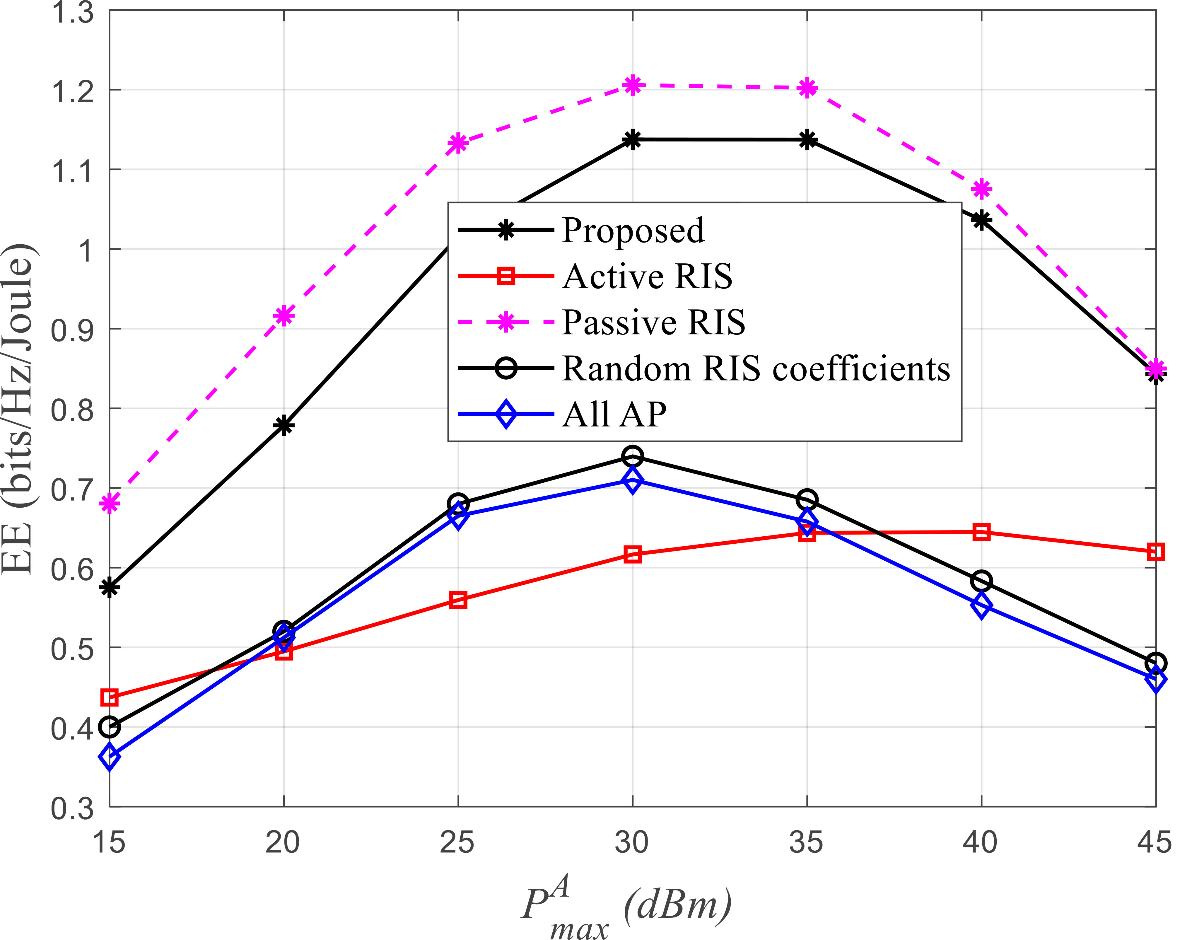
To begin with, the EE performance is analyzed with increasing transmit power at the APs illustrated in Fig. 2(a). We consider each RIS are configured with Ns=80subscript𝑁𝑠80N_{s}=80 elements including Na=3subscript𝑁𝑎3N_{a}=3 active ones. The maximum RIS transmit power is assumed as PmaxR=10 dBmsuperscriptsubscript𝑃𝑚𝑎𝑥𝑅10 dBmP_{max}^{R}=10\text{ dBm}. We can see from the figure that the EE of the system first grows with transmit power AP increases, and then drops for each configuration. The proposed algorithm for the hybrid RIS significantly outperforms the active RIS (Na=Nssubscript𝑁𝑎subscript𝑁𝑠N_{a}=N_{s}), random RIS coefficients and all AP cases, where all AP means to replace the RISs with APs. For fairness, the overall transmit power keeps unchanged. In addition, the EE performance of the proposed algorithm with hybrid RISs approaches about 96%percent9696\% of that with conventional fully passive RISs with the AP transmit power increasing.
Refer to caption
(a) Energy efficiency versus transmit power at APs
Refer to caption
(b) Sum rate versus transmit power at APs
Refer to caption
(c) Energy efficiency versus the number of iterations
Figure 2: Simulation results

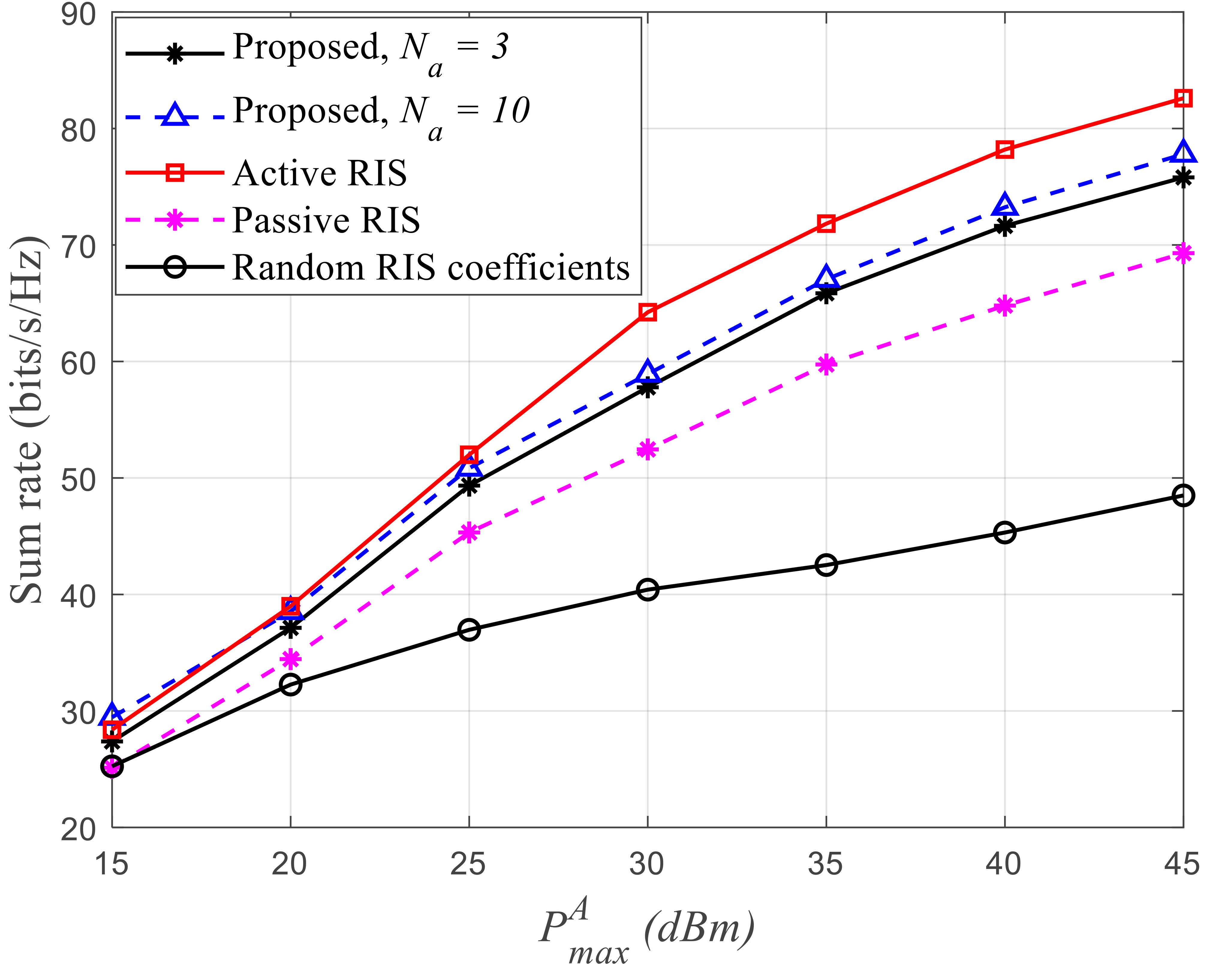
We further investigate the sum rate performance of the proposed system versus transmit power at the APs. From Fig. 2(b), the system achievable sum rate is keep increasing with higher AP transmit power budget. Specifically, active RISs aided cell-free networks achieves better sum rate than other cases. The hybrid RISs with Na=10subscript𝑁𝑎10N_{a}=10 active elements slightly performs better than those with only Na=3subscript𝑁𝑎3N_{a}=3 active elements. The effectiveness of the proposed algorithm can be seen compared with passive RIS and random RIS coefficients cases. Combined with results in Fig. 2(a), it can be inferred that the hybrid RIS takes into account a trade-off between EE and sum rate performance, compared with active and passive RISs.

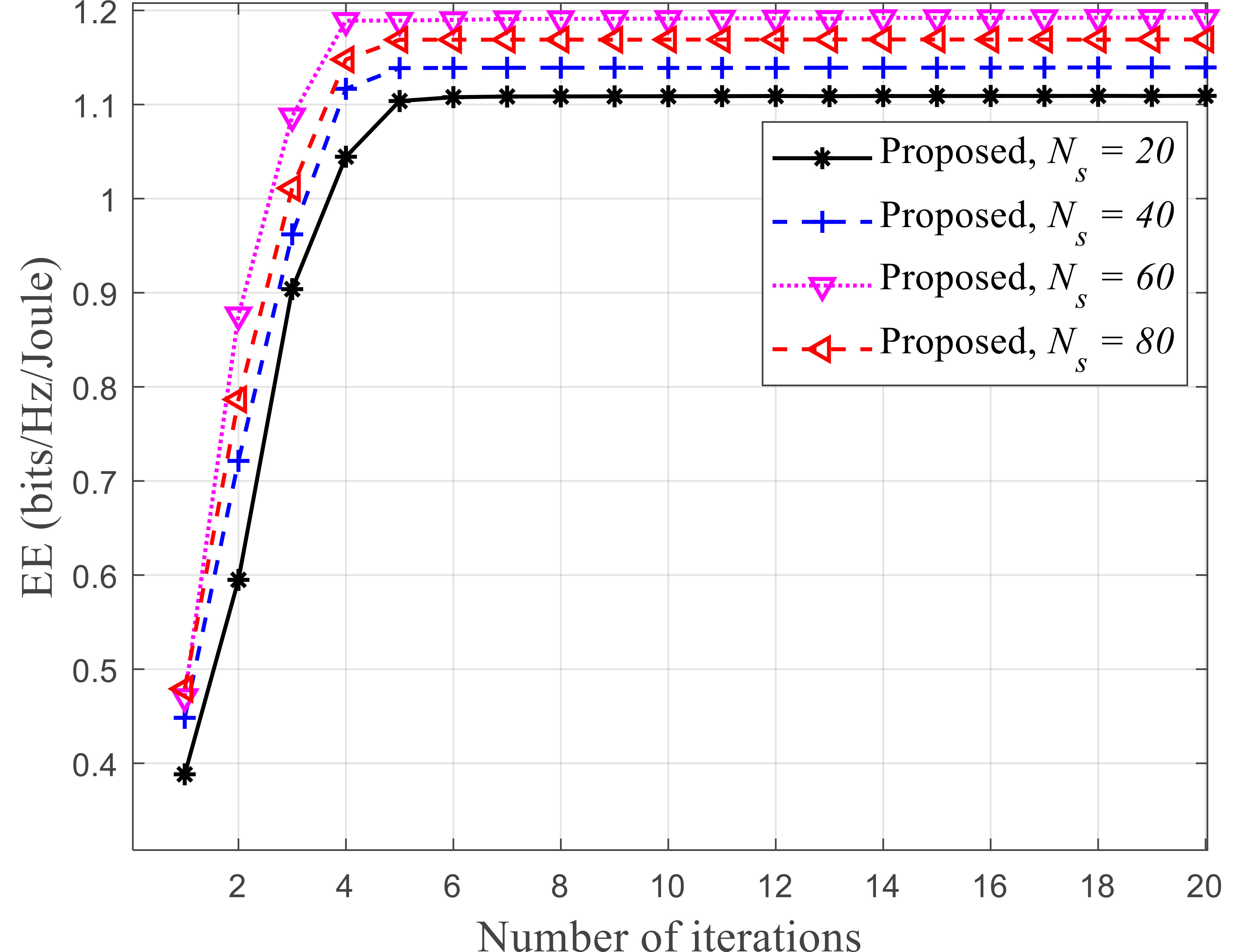
The convergence of the proposed algorithm is verified in Fig. 2(c), from which we can see the results converges fast within around 555 iterations. Influence of different numbers of RIS elements Nssubscript𝑁𝑠N_{s} is analyzed as well. By increasing Nssubscript𝑁𝑠N_{s} from 202020 to 606060, the EE performance is improved due to the diversity gain of more RIS elements. Then the system EE drops slightly with Ns=80subscript𝑁𝑠80N_{s}=80, since a larger scale of RIS has higher circuit power consumption.

V Conclusion

In this letter, we studied a hybrid RISs assisted cell-free network. The energy efficiency maximization problem was formulated by jointly optimizing the transmit beamforming and hybrid RIS coefficients design. We first transform the coupled fractional objective function into a concave form by introducing slack variables. Then, a BCD based iterative algorithm was proposed to solve the non-convex problem with SCA method. The simulation results showed that the proposed hybrid RISs algorithm can achieve comparable sum rate as active RISs but as energy-efficient as passive RISs. Also, the fast convergence was verified by the numerical results as well.

References

  • [1] F. E. Idachaba, “5g networks: Open network architecture and densification strategies for beyond 1000x network capacity increase,” in 2016 Future Technologies Conference (FTC), 2016, pp. 1265–1269.
  • [2] Z. Zhang and L. Dai, “A joint precoding framework for wideband reconfigurable intelligent surface-aided cell-free network,” IEEE Transactions on Signal Processing, vol. 69, pp. 4085–4101, 2021.
  • [3] E. Nayebi, A. Ashikhmin, T. L. Marzetta, and H. Yang, “Cell-free massive mimo systems,” in 2015 49th Asilomar Conference on Signals, Systems and Computers, 2015, pp. 695–699.
  • [4] A. Papazafeiropoulos, P. Kourtessis, M. D. Renzo, S. Chatzinotas, and J. M. Senior, “Performance analysis of cell-free massive mimo systems: A stochastic geometry approach,” IEEE Transactions on Vehicular Technology, vol. 69, no. 4, pp. 3523–3537, 2020.
  • [5] E. Nayebi, A. Ashikhmin, T. L. Marzetta, and H. Yang, “Cell-free massive mimo systems,” in 2015 49th Asilomar Conference on Signals, Systems and Computers, 2015, pp. 695–699.
  • [6] J. Zhang, S. Chen, Y. Lin, J. Zheng, B. Ai, and L. Hanzo, “Cell-free massive mimo: A new next-generation paradigm,” IEEE Access, vol. 7, pp. 99 878–99 888, 2019.
  • [7] M. Giordani, M. Polese, M. Mezzavilla, S. Rangan, and M. Zorzi, “Toward 6g networks: Use cases and technologies,” IEEE Communications Magazine, vol. 58, no. 3, pp. 55–61, 2020.
  • [8] Y. Zhang, B. Di, H. Zhang, J. Lin, C. Xu, D. Zhang, Y. Li, and L. Song, “Beyond cell-free mimo: Energy efficient reconfigurable intelligent surface aided cell-free mimo communications,” IEEE Transactions on Cognitive Communications and Networking, vol. 7, no. 2, pp. 412–426, 2021.
  • [9] Q. Wu and R. Zhang, “Towards smart and reconfigurable environment: Intelligent reflecting surface aided wireless network,” IEEE Communications Magazine, vol. 58, no. 1, pp. 106–112, 2020.
  • [10] M. Najafi, V. Jamali, R. Schober, and H. V. Poor, “Physics-based modeling and scalable optimization of large intelligent reflecting surfaces,” IEEE Transactions on Communications, vol. 69, no. 4, pp. 2673–2691, 2021.
  • [11] R. Long, Y.-C. Liang, Y. Pei, and E. G. Larsson, “Active reconfigurable intelligent surface-aided wireless communications,” IEEE Transactions on Wireless Communications, vol. 20, no. 8, pp. 4962–4975, 2021.
  • [12] Z. Zhang, L. Dai, X. Chen, C. Liu, F. Yang, R. Schober, and H. V. Poor, “Active RIS vs. Passive RIS: Which Will Prevail in 6G?” arXiv e-prints, p. arXiv:2103.15154, Mar. 2021.
  • [13] N. T. Nguyen, Q.-D. Vu, K. Lee, and M. Juntti, “Spectral efficiency optimization for hybrid relay-reflecting intelligent surface,” in 2021 IEEE International Conference on Communications Workshops (ICC Workshops), 2021, pp. 1–6.
  • [14] ——, “Hybrid relay-reflecting intelligent surface-assisted wireless communications,” IEEE Transactions on Vehicular Technology, vol. 71, no. 6, pp. 6228–6244, 2022.
  • [15] N. T. Nguyen, V.-D. Nguyen, Q. Wu, A. Tölli, S. Chatzinotas, and M. Juntti, “Hybrid active-passive reconfigurable intelligent surface-assisted multi-user miso systems,” in 2022 IEEE 23rd International Workshop on Signal Processing Advances in Wireless Communication (SPAWC), 2022, pp. 1–5.
  • [16] N. Landsberg and E. Socher, “Design and measurements of 100 ghz reflectarray and transmitarray active antenna cells,” IEEE Transactions on Antennas and Propagation, vol. 65, no. 12, pp. 6986–6997, 2017.
  • [17] D. L. Galappaththige, D. Kudathanthirige, and G. Amarasuriya, “Performance analysis of irs-assisted cell-free communication,” in 2021 IEEE Global Communications Conference (GLOBECOM), 2021, pp. 1–6.
  • [18] B. Al-Nahhas, M. Obeed, A. Chaaban, and M. J. Hossain, “Ris-aided cell-free massive mimo: Performance analysis and competitiveness,” in 2021 IEEE International Conference on Communications Workshops (ICC Workshops), 2021, pp. 1–6.
  • [19] W. Dinkelbach, “On nonlinear fractional programming,” Management Science, vol. 13, 1967.
  • [20] S. Boyd and L. Vandenberghe, Convex Optimization.   Cambridge university press, 2004.
  • [21] J. Nocedal and S. Wright, Numerical Optimization.   New York, NY, USA: Springer, 2006.
  • [22] T. Noh and J. Choi, “Cell-free mimo systems powered by intelligent reflecting surfaces,” IEEE Communications Letters, vol. 26, no. 5, pp. 1076–1080, 2022.
  • [23] R. Huang and V. W. Wong, “Towards reliable communications in intelligent reflecting surface-aided cell-free mimo systems,” in 2021 IEEE Global Communications Conference (GLOBECOM), 2021, pp. 1–6.
  • [24] B. R. Marks and G. P. Wright, “A general inner approximation algorithm for nonconvex mathematical programs,” Operations Research, vol. 26, no. 4, pp. 681–683, 1978.
  • [25] K. Shen and W. Yu, “Fractional programming for communication systems—part i: Power control and beamforming,” IEEE Transactions on Signal Processing, vol. 66, no. 10, pp. 2616–2630, 2018.
  • [26] L. You, J. Xiong, D. W. K. Ng, C. Yuen, W. Wang, and X. Gao, “Energy efficiency and spectral efficiency tradeoff in ris-aided multiuser mimo uplink transmission,” IEEE Transactions on Signal Processing, vol. 69, pp. 1407–1421, 2021.
  • [27] Y. Xiu, J. Zhao, C. Yuen, Z. Zhang, and G. Gui, “Secure beamforming for multiple intelligent reflecting surfaces aided mmwave systems,” IEEE Communications Letters, vol. 25, no. 2, pp. 417–421, 2021.
  • [28] Y. Cheng, W. Peng, C. Huang, G. C. Alexandropoulos, C. Yuen, and M. Debbah, “Ris-aided wireless communications: Extra degrees of freedom via rotation and location optimization,” IEEE Transactions on Wireless Communications, vol. 21, no. 8, pp. 6656–6671, 2022.
  • [29] Z. Yang, M. Chen, W. Saad, W. Xu, M. Shikh-Bahaei, H. V. Poor, and S. Cui, “Energy-efficient wireless communications with distributed reconfigurable intelligent surfaces,” IEEE Transactions on Wireless Communications, vol. 21, no. 1, pp. 665–679, 2022.
  • [30] Z. Ji, P. L. Yeoh, D. Zhang, G. Chen, Y. Zhang, Z. He, H. Yin, and Y. li, “Secret key generation for intelligent reflecting surface assisted wireless communication networks,” IEEE Transactions on Vehicular Technology, vol. 70, no. 1, pp. 1030–1034, 2021.
  • [31] Y. Xu, H. Xie, Q. Wu, C. Huang, and C. Yuen, “Robust max-min energy efficiency for ris-aided hetnets with distortion noises,” IEEE Transactions on Communications, vol. 70, no. 2, pp. 1457–1471, 2022.
  • [32] C. Huang, A. Zappone, G. C. Alexandropoulos, M. Debbah, and C. Yuen, “Reconfigurable intelligent surfaces for energy efficiency in wireless communication,” IEEE Trans. Wireless Commun., vol. 18, no. 8, pp. 4157–4170, 2019.
  • [33] M. Di Renzo, A. Zappone, M. Debbah, M.-S. Alouini, C. Yuen, J. de Rosny, and S. Tretyakov, “Smart radio environments empowered by reconfigurable intelligent surfaces: How it works, state of research, and the road ahead,” IEEE J. Sel. Areas Commun., vol. 38, no. 11, pp. 2450–2525, 2020.
  • [34] C. Huang, Z. Yang, G. C. Alexandropoulos, K. Xiong, L. Wei, C. Yuen, Z. Zhang, and M. Debbah, “Multi-hop ris-empowered terahertz communications: A drl-based hybrid beamforming design,” IEEE J. Sel. Areas Commun., vol. 39, no. 6, pp. 1663–1677, 2021.