Edilson S. Palma et al
Maria Istela Cagnin, College of Computing, Federal University of Mato Grosso do Sul, Zip Code 79070-900, Campo Grande, Brazil
Evolving Reference Architecture Description:
Guidelines based on ISO/IEC/IEEE 42010
Abstract
[ABSTRACT] The architectural design of software systems is not a trivial task, requiring sometimes large experience and knowledge accumulated for years. Reference architectures have been increasingly adopted as a means to support such task, also contributing to the standardization and evolution of these systems. Although considerable time and effort are devoted to design these architectures, an outdated description is still found in several of them and, as a consequence, resulting in their non-continuation. This article presents guidelines to evolve the description of reference architectures, considering different types of stakeholders and required tasks. To complement our statement that the guidelines are correct by construction as they were grounded in widely known international standard ISO/IEC/IEEE 42010 and literature, we also briefly present a qualitative analysis comparing the guidelines with an ad hoc way (commonly occurred in reference architectures). We believe solutions like these guidelines are necessary and could further contribute to the sustainability and longevity of reference architectures.
keywords:
Reference Architecture, Architectural Description, Evolution1 Introduction
As an earlier step of the software development process, the architectural design deals with the establishment of software architectures that describe software elements, externally visible properties of these elements, and relationships among them Bass:2012:SAP:2392670. The establishment of a suitable architecture that meets functional and non-functional requirements is not a trivial task, requiring for that technical knowledge, experience, and skill accumulated for years. In this scenario, reference architectures have been increasingly adopted as a means to facilitate the architectural design of software systems, promoting the reuse of architectural decisions, good practices, software elements, and so on, and generally speaking, the knowledge accumulated about how to architect systems in a given domain Nakagawa2014 Zhao2003. Good examples of these architectures are Autosariiihttps://www.autosar.org (for automotive sector), ARC-ITiiiiiihttps://local.iteris.com/arc-it/index.html (for cooperative and intelligent transportation), and RAMI 4.0 iiiiiiiiihttps://www.plattform-i40.de/PI40/Redaktion/EN/Downloads/Publikation/rami40-an-introduction.html (for Industry 4.0). In particular, the main difference between software architecture and reference architecture is that software architecture is a design solution for a specific software system; on the other hand, reference architecture offers a high-level design solution for a class of similar software systems belonging to a given domain. Due to this, reference architecture is more abstract than software architecture and must be instantiated and configured to attend the specificities of software being built (ISO/IEC/IEEE 42010 iso42010; Nakagawa et al. Nakagawa:2011:RAP:2041790.2041818; Galster and Avgeriou galster2011empirically; Bass et al. Bass:2012:SAP:2392670; Nakagawa et al. Nakagawa2014).
A wider adoption of reference architectures depends directly on how appropriate their descriptionivivivIn this work, the terms architectural description, architectural documentation, and architectural representation have the same meaning. is. Initiatives already exist to build adequate descriptions Guessi2011; however, a number of architectures still have an outdated description in the sense that they were proposed, sometimes presented through some publications and, after that, such description is not updated, even those ones where their related application domain continually evolve. Evolution of reference architectures is necessary to comply with external agents (such as new laws, emergent technologies, new target platforms, new architectural styles and patterns) or internal issues (such as change of the business rules, new non-functional requirements, improvements/refinements in requirements), resulting in non-sustainable reference architectures Venters18SSRP. For instance, Autosar does not still support the development of automotive systems for 100% autonomous cars. Thus, due to all the demands of the market/business, there is a need to soon evolve Autosar. Moreover, despite the importance of a systematic way to evolve the description of reference architectures, to the best our knowledge, none specific work has been conducted in that direction.
The main goal of this article is to present guidelines to systematically evolve the description of reference architectures. To establish these guidelines, problems and shortcomings found in reference architecture descriptions were identified based on a checklist of reference architectures assessment, called FERA (Framework for Evaluation of Reference Architectures) santos2013checklist and, thereafter, were analyzed and summarized. Following, based on ISO/IEC/IEEE 42010 iso42010 (an international standard for software architecture description) and on works about software architectures evolution Sadou2005 Wang20132701 Ding2001191 adapted to the reference architectures context, we established our guidelines, which guide “what to do”, “how to make”, “how to represent”, and “which evolution tasks and rules” are needed. Due to this large foundation, we believe the guidelines are “correct by construction”vvv“Correct by construction” is commonly used in formal verification techniques to demonstrate that a system design is correct with respect to its specification. We “lent” this term to say our guidelines are correct with respect to what the software architecture community has required to perform architectural descriptions., but we additionally present a brief qualitative analysis to show the ease and viability to use these guidelines. Results pointed out they can more efficiently guide and facilitate the evolution of reference architecture description in comparison with an ad hoc way, i.e., the way how descriptions have been commonly updated. We believe these guidelines could be considered as a first and motivating step to systematize the evolution tasks and, as a consequence, they could contribute to become reference architectures sustainable along the time.
The remainder of this article is organized as follows. Section 2 presents a background related to our work and also discusses the related work concerned with the evolution of software architectures; some of them adapted in this work to the context of reference architectures. Section 3 presents our guidelines and the research method to establish them. Section 4 briefly presents both the planning and conduction of the qualitative analysis. Section 5 discusses on our findings and limitations, and presents perspectives for future works. Finally, Section 6 concludes this work.
2 Background and Related Work
Reference architectures contain knowledge about how to design concrete architectures for a given application domain. They include business rules, architectural styles and patterns that address quality attributes, best practices for software development (e.g., architectural decisions, domain constraints, legislations and standards), and software elements that support the development of software systems for that domain Nakagawa:2011:RAP:2041790.2041818. In addition, they can increase the effectiveness of the concrete architectures of a domain, helping to avoid rework with problems already solved Cloutier:SYS20129.
As a software artifact, reference architectures also require a systematized process to be designed. In the literature, there are some processes with this aim, such as ProSA-RA Nakagawa2014, which have some steps in common: i) “Architectural Analysis” that deals with the collection and analysis of information sources to understand the target domain and to establish the architectural requirements of the reference architecture; ii) “Architectural Synthesis” that deals with the reference architecture design based on previously defined architectural requirements; and iii) “Architectural Evaluation” that assesses the quality of the reference architecture.
During the architectural synthesis of a reference architecture, its description is built based on: (i) the architectural requirements identified for the reference architecture; (ii) the concepts of the target domain; and (iii) the architectural styles and patterns. For supporting this, authors Guessi2014162 Regli2014 establish architectural viewpoints and views to better represent reference architectures, taking into account their stakeholders and nature Nakagawa2014. It is important to emphasize that each view is the representation of the reference architecture as a whole, according to the needs of stakeholders.
In particular, ISO/IEC/IEEE 42010 iso42010, which addresses the architectural description and is also basis of some works about reference architecture description, does not present how the description should be made, neither what architectural description languages or views should be used, but indicates which elements should be considered to represent a software architecture.
The description of reference architectures also needs to evolve mainly due to deficiencies and defects identified after an evaluation, for example, using assessment checklists as FERA checklist santos2013checklistviviviThe current version of FERA containing 118 questions divided in four groups was reported in a journal paper under review in this moment and, therefore, not available completely in this work., or after evolution of the reference architectures themselves in which new requirements arisen or were not previously elicited. In case of reference architecture evolution, new elements can be incorporated, existing elements can be adapted, eliminated, and replaced to meet the new needs of the stakeholders.
We conducted a search to find works that propose or use approaches, processes, guidelines or techniques to the evolution of descriptions of reference architectures; however, no studies were found. Then, we conducted another search to find works addressing software architectures evolution that were also considered as information sources to establish our guidelines. It is worth detailing three main studies Sadou2005, Wang20132701, Ding2001191.
The FOCUS approach Ding2001191 assists the recovery of architecture from source code of object-oriented systems as well as evolution of such architectures. This approach is composed of two stages: architectural recovery and architectural evolution. The first one aims to understand and document the architectures considering their logical and physical characteristics. The second stage, which is of our interest, evolves architectures based on an evolution plan. The evolution involves components added or modified and control flow among components updated. If necessary, new evolution iterations are performed at a lower level of granularity to evolve components increasingly specific.
Another work Wang20132701 investigates architectural evolution in the context of agile methods. The authors report that in agile methods the source code represents the software architecture itself and that architectural evolution is not something formal. In addition, iteration is the core of the process of architectural evolution, since new stories and those that need to be modified are included. Each iteration deals with the definition of the architecture, the construction of the architectural prototype, the implementation and the verification of the architecture and, finally, the release of the architecture that corresponds to the delivery of functional software. The authors explain the following operations that can occur in the software architecture evolution: add components, modify components, delete components, combine components, and split components. To identify the most appropriate operation, it is necessary to analyze the complexity between the relationships of the original components and the new components, as well as the connection and interaction between the static components.
Another work proposed an evolution model, called SAEV (Software Architecture EVolution model) Sadou2005, which describes and controls the software architectures evolution at different levels of granularity as well as the evolution of software systems based on it. In particular, this model focuses on static (which occurs during software architecture specification) and dynamic (which occurs during software architecture execution) evolutions of software architectures. For this, SAEV considers during the architectural evolution all the architectural elements proposed by ADL (Architectural Description Languages), such as components, connectors, interfaces, and configurations. Additionally, this model defines the evolution operations (addition, removal, modification or replacement of architectural elements), evolution rules (that indicate the event that must occur to start the rule, the conditions that must be satisfied to perform the operation when the event occurs, as well as the actions to be performed), and evolution strategies (that represent the set of evolution rules describing all evolution operations applicable to each architectural element).
It should be noted that the aforementioned works Sadou2005, Wang20132701, Ding2001191 consider similar operations to the architectural evolution of software architectures; however, each of them uses specific mechanisms to identify the most appropriate operation to each case of evolution.
3 Guidelines to the Evolution of Descriptions of Reference Architectures
The guidelines intend to help software architects to systematically evolve reference architecture descriptions to minimize their deficiencies. Besides that, these guidelines could increase the quality of such descriptions, aligned to the need of less effort and time to evolve such descriptions. The subsections following describe: (i) the information source used to specify the guidelines; (ii) how the structure and content of the guidelines were defined; and (iii) a roadmap and an example of their use.
3.1 Information Sources
We initially analyzed works that proposed and used methods to evaluate reference architectures themselves to obtain the evolution requirements that could be considered during the evolution of a reference architecture description and that should be treated by the guidelines. From this analysis, we identified the possible shortcomings of reference architectures that lead to the evolution of their description.
Three main works gallagher2000using graaf2005evaluating angelov2008towards presented adaptations of software architectures assessment methods to the evaluation of reference architectures, focusing on architectural elements related to the quality of these architectures. In addition to these works, the FERA checklist santos2013checklist also proposed to evaluate reference architectures under the aspects of quality attributes and aspects related to architectural representation, i.e., FERA is based on ISO/EIC 42010. Due to such characteristics and its use in the assessment of several reference architectures belonging to academia and industry osshiro2018cambuci PORTOCARRERO20173 Portocarrero:2015 rodriguez2015reference duarte2015contribution, FERA was selected as an information source to establish our guidelines. FERA consists of four parts (Part 1 - General Information, Part 2 - Construction and Content, Part 3 - Appropriate Architectural Description and Part 4 - General Analysis and Conclusion) and each part contains questions answered by different types of stakeholders of reference architectures, such as software architect, domain expert, manager, developer, software quality assurance specialist, tester, and systems analyst (i.e., those interested in the conception, construction, validation, and use of reference architectures). The possibility of evaluations conducted from the perspective of several stakeholders was another reason to use this checklist in our work. Each question of FERA provided us requirements to specify our guidelines and to establish what each guideline should address to deal with shortcomings and defects in the descriptions of reference architectures.
Studies about software architectures description and evolution (discussed briefly in Section 2) were also considered to built the guidelines, since no studies were found related to the evolution of descriptions of reference architectures. Moreover, a systematic literature review about reference architecture representation, previously conducted in 2011 by Guessi et al. Guessi2011, was updated for this work that identified other 21 studies AndhariniDwi2015284, Szwed2015222, Branscomb201379, Braun201148, DeLaCruz2011305, Filho2015, Gringinger2012, Guessi2014162, Guessi:2015:TFD:2755567.2755571, Guessi2014, Turek2015, Kruize201375, Lopes2011441, Ma2013197, Mafazi2014, Nakagawa2012297, Nakagawa2014, Paschke2012, Pereira2014185, Regli2014, Stocker2015. These studies were used in our work to identify how to perform the reference architecture description, what supported us to propose our guidelines. To complement, another study of Guessi Guessi2013mestrado, which defines a method to describe reference architecture for embedded systems, was also used to identify architecture views and viewpoints to describe reference architectures.
3.2 Structure and Content of the Guidelines
Based on the information sources identified, the structure and content of the guidelines were defined, as described below and summarized in Figure 1viiviiviiRepresented in Business Process Model and Notation (BPMN)..

Firstly, the structure of the guidelines was defined. For this, we used as the basis SAEV Sadou2005, including their important concepts: architectural element, evolution operation, evolution rule, and evolution strategy. These concepts were mapped in our work, respectively, as element, evolution task, evolution rule, and evolution guideline.
Elements represent the architectural elements that are considered for the evolution of reference architecture description (e.g., Variability element, ViewPoint Element, View Element, Instantiation Element, etc). Such elements are composed of one or more components (e.g., description of a viewpoint, representation block of a model belonging to a view, etc).
Evolution tasks are classified into three types: addition, removal, and modification; which respectively add, remove or modify elements and components in a reference architecture description. The definition of these tasks were based on works described in Section 2 Wang20132701, Ding2001191 and mainly the SAEV model Sadou2005, which identifies evolution rules for each one of the evolution tasks.An evolution task is composed of one or more evolution rules, and such rules are represented based on the ECA (Event/Condition/Action) formalism, used in Sadou2005. Each evolution rule has an event, which specifies when the rule should be triggered; a condition, which is evaluated when the event occurs, enabling the execution of the rule only if such conditions are true; and an action that must be performed when the event occurs and the conditions are satisfied.
Moreover, an evolution guideline must provide a solution to solve any deficiency of a reference architecture description found by an assessment based on FERA (“what to do”). Knowing what needs to be done, it is essential to point out “how to represent” the solution in the reference architecture description, “how to make” to evolve a reference architecture description and which artifacts are important to be considered for the execution of each proposed guideline.
Hence, the structure to document each guideline is composed of an Identifier (according to the format D_[Element]_[ Sequential number]), the Element (that represents the category of FERA’s questions handled by the guideline), the Identifiers of FERA’s questions addressed by the guideline (according with the format [Group of FERA] - [Identifier of FERA’s question]), What to do, How to represent, How to make, the Evolution tasks and rules, and the Artifacts involved to carry out the evolution. In the case of the evolution rules, they present an Identifier (in the format R-[Acronym of the guideline in lowercase]-[Sequential number]), the Event that triggers the rule, the necessary Condition to start the execution of the rule, and the Action itself.
Afterwards, we categorized the FERA’s questions. For this, all 118 questions of FERA were sorted systematically applying the Open Coding technique strauss1998basicsgrounded. Each code was firstly identified by the first author of this paper based on concepts addressed for each FERA’s question. For instance, in the question “Is there traceability between the domain objectives and the technical solution?” of FERA, the codes identified were DomainData and TechnicalSolution and in the question “Is there a clear description of which parts of the reference architecture are fixed and which parts are subject to instantiation in a concrete organization/context?” the code was Variability. To accomplish this task, we used R softwareviiiviiiviiihttps://www.R-project.org and package RQDAixixixhttp://rqda.r-forge.r-project.org, which helped us to label each question by inserting the codes of interest. Iteratively, each code generated was discussed, reviewed, and validated by all other authors. Consensus meetings were also held to discuss the codes extracted and their relationships.
It is noteworthy that it was necessary to create codes identified from the FERA’s questions that are beyond what is covered by ISO/IEC/IEEE 42010. These codes were concerned: (i) with important aspects not addressed by the standard (instantiation code), (ii) specific aspect of reference architectures (variability code), and (iii) others elements and artifacts of reference architecture life cycle considered relevant by FERA to be evaluated (acquisition, test, quality, risk or threat, evolution, domain data, information source, module and technical solution codes).
Following, the conceptual model illustrated in Figure 2xxxWe represented the conceptual model using the notation of UML class diagram. was elaborated containing 24 concepts. To build it, all identified categories were represented as concepts and shown in the diagram exhibited in this figure. While categories related to FERA’s questions and to ISO/IEC/IEEE 42010 are presented as classes in white background, other new categories are presented as classes in gray background. In addition, the identifier of the FERA’s questions (in the format “Part-Question”), which were classified in each category, are presented in the class related to that category. For instance, in the category “Viewpoint”, there are seven questions, including Question 15 of Part 1 (i.e., 1-15). This question is “All selected viewpoints for the reference architecture were considered?”, which in fact is related to the category Viewpoint. Another example is the category DomainData that has 13 questions, where for instance Question 35 of Part 2 is “Is the reference architecture in conformance with the requirements document?”, i.e., such question asks about domain data into the reference architecture.
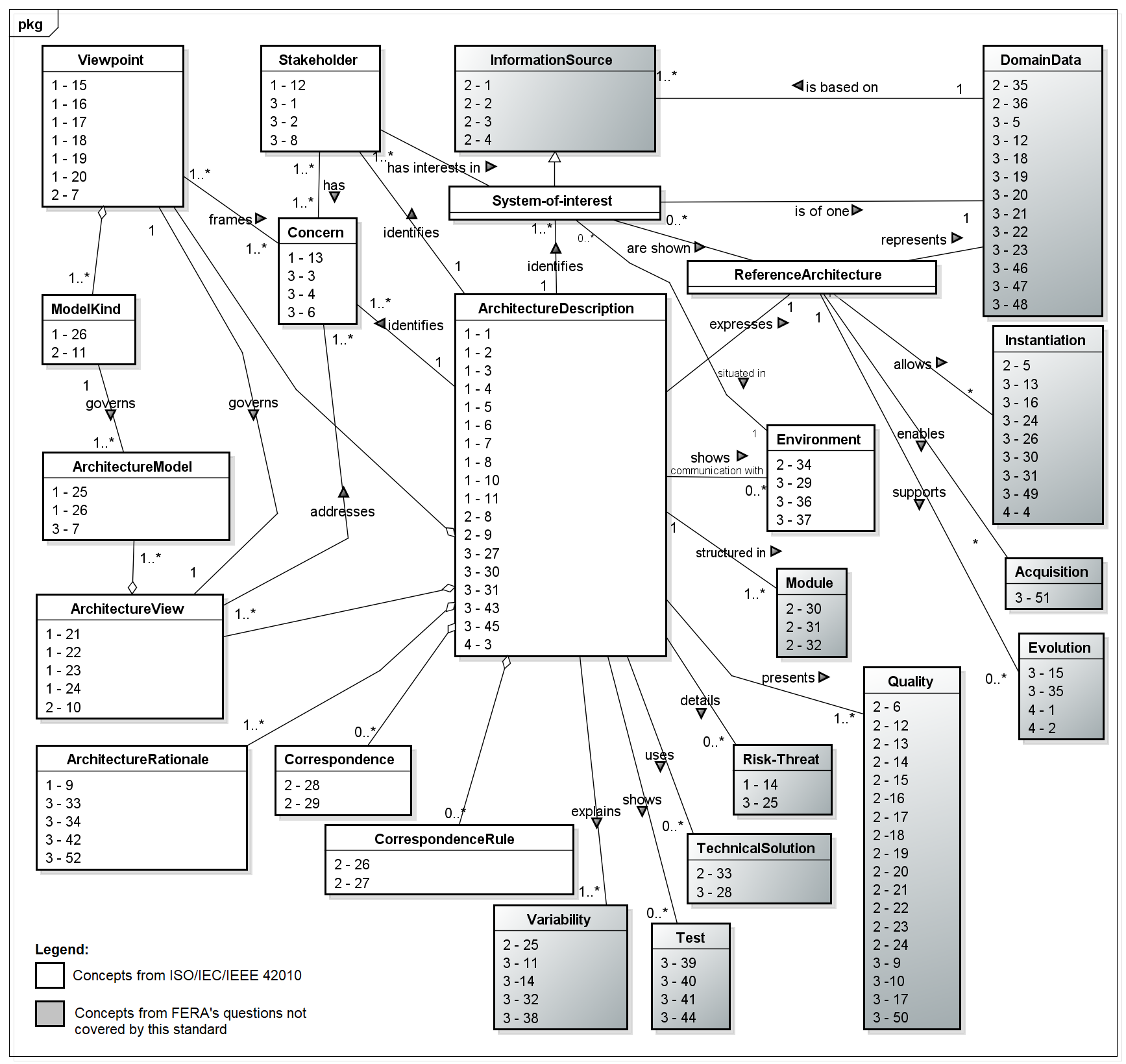
Regarding the relationships among the concepts, they were established in accordance with the ISO/IEC/IEEE 42010. Relationships with the concepts obtained from FERA’s questions that are beyond what is covered by this standard were created based on the context of these questions. In particular, a relationship was included between two existing concepts, that is ArchitectureDescription and Environment, as there exist four FERA’s questions (whose identifiers are 2-34, 3-29, 3-36, 3-37) related to the reference architecture and its external environment and must be considered by its description.
The conceptual model was useful to understand the elements involved in the reference architecture description and that shall be carefully considered during its building and evolution. In addition, this conceptual model was very helpful during the guidelines construction, as it explains the elements that should be addressed by the guidelines and also contains the identifiers of the FERA’s questions. From these identifiers, all information about the questions was obtained to define the guidelines.
After categorizing the questions, we took the categories as base to raise the corresponding architectural elements to be evolved (according to the third activity of Figure 1). Next, we started the elaboration of the guidelines for each raised architectural element, and detailed in Algorithm 1. FERA’s questions corresponding to each element were analyzed to identify evolution requirements. Then, for each requirement, an evolution guideline was created. For this, we find solutions (what to do) to solve them, i.e., what is necessary to be done in the description of reference architectures for that the corresponding questions are answered positively during a reference architecture evaluation. Questions associated with each architectural element predisposed to evolve and that share a similar solution were grouped into the same guideline. Hence, one or more guidelines may be associated with a single element.
-
•
Establish the “Evolution tasks” with the respective “Evolution rules”
-
•
Identify the “Artifacts” that should be considered to evolve the reference architecture description
Subsequently, we analyzed how to represent the solution in the reference architecture description, based on the studies found in Guessi2013mestrado, AndhariniDwi2015284, Szwed2015222, Branscomb201379, Braun201148, DeLaCruz2011305, Filho2015, Gringinger2012, Guessi2014162, Guessi:2015:TFD:2755567.2755571, Guessi2014, Turek2015, Kruize201375, Lopes2011441, Ma2013197, Mafazi2014, Nakagawa2012297, Nakagawa2014, Paschke2012, Pereira2014185, Regli2014, Stocker2015, which contain works about views and viewpoints to represent reference architectures. Next, we defined how to make to evolve a reference architecture description. For this, we considered two steps (“Architectural Analysis” and “Architectural Synthesis”) commonly found in processes to build such architectures such as ProSA-RA, and that should be executed based on “what to do” and “how to represent” previously discussed. When it is necessary to obtain new information sources or to analyze existing ones, we indicate the execution of the “Architectural Analysis” step; otherwise, we recommend the execution of the “Architectural Synthesis” step. The first step contains activities that guide architects making it possible to examine the information source and the second step is executed with the support of evolution tasks, defined based on “what to do” and “how to represent”, and provided by the guidelines to effectively carry out the evolution of the architectural description. In parallel, we identified important artifacts (such as architectural description and traceability matrix) that should be considered for the execution of each proposed guideline. Finally, the guideline is documented based on the previously defined structure.
Ultimately, we identified 52 guidelines associated to 22 elementsxixixiNo guideline was associated with the categories System-of-interest and Reference Architecture, since they do not represent elements that make up the architectural description and, therefore, they are not elements of evolution interest. together with their evolution rules, as illustrated in Table 1 (that shows a given guideline) and Table 2 (that shows one of the evolution rules of this guideline). Other five guidelines are presented in Appendix Axiixiixiihttps://goo.gl/gqyF2o.
Regarding the guideline in Table 1, it deals with the Variability element in reference architecture description. This guideline points out that all elements of the reference architecture shall be mapped as mandatory or variable, aiming at expliciting and documenting the domain variability covered by reference architecture. For this, this guideline indicates several existing techniques that can be used by the architect during the description evolution, as well as how to make the evolution, the needed artifacts and the evolution tasks and rules that must be carried out. In a nutshell, R-var-1 (presented in Table 2) details that a Variability View must be created (whether it does not exist), a Model Kind must be chosen according to one of the adopted techniques to document variability, the Variability Model must be created according to Model Kind chosen, a suitable Viewpoint must be created (whether it does not exist) and the Variability View must be incorporated. Then, the Variability Model is added in the Variability View and the Traceability Matrix is updated. R-var-2 indicates that the Variability Model and the Variability View must be removed and the Traceability Matrix must be updated. R-var-3 specifies that the relevant modifications regarding variability must be incorporated in the Variability Model and the Traceability Matrix must be updated, if pertinent.
| Guideline |
|
|||
|---|---|---|---|---|
| Element | Variability | |||
|
|
|||
| What to do |
|
|||
|
|
|||
| How to make |
|
|||
|
||||
|
||||
| Evolution tasks and rules |
|
|||
|
|
|
|
||||||||
|---|---|---|---|---|---|---|---|---|---|
| Event | Add Variability element. | ||||||||
| Condition |
|
||||||||
| Action |
|
3.3 Context and Use of the Guidelines
Besides applying the guidelines during the evolution of reference architectures (in particular, on their description), they could be applied during the design of such architectures early providing direction that could reduce further time/effort for evolution.
To facilitate the use of the most appropriate guidelines, the index shown partially in Table 3 (that shows two of 22 elements) was created and contains: (i) the element; (ii) the identifier of the guidelines; (iii) the FERA’s questions that each guideline can be applied; and (iv) the evolution tasks and rules associated with each guideline. Besides that, the roadmap presented in Algorithm 2 provides steps that guide the use of the guidelines.
| Element | Guideline Name |
|
|
|
||||||
| Addition | R-fi-1; R-fi-2 | |||||||||
| Removal | - | |||||||||
| Information Source | D_Information_Source_1 | 2-1; 2-2; 2-3; 2-4 | Modification | R-fi-3 | ||||||
| Addition | - | |||||||||
| Removal | - | |||||||||
| D_Instantiation_1 | 2-5; 4-4 | Modification |
|
|||||||
| Addition | R-ins-1; R-ins-2; R-ins-4 | |||||||||
| Removal | - | |||||||||
| D_Instantiation_2 | 3-13; 3-24 | Modification | R-ins-3; R-ins-5 | |||||||
| Addition | R-ins-6 | |||||||||
| Removal | - | |||||||||
| Instantiation | D_Instantiation_3 | 3-16 | Modification | R-ins-7 |
4 Qualitative Analysis
The objective of the qualitative analysis was to compare our guidelines with an ad hoc approach to evolve the description of a service-oriented reference architecture for software assets repositories, the Cambuci osshiro2018cambuci. For the participants of the group that used the ad hoc method, they received the description of Cambuci and the ISO/IEC/IEEE 42010. These participants could evolve the description of Cambuci using their knowledge of how to represent software architectures (obtained through the training provided and described in Section 4.1 and also by consulting the ISO/IEC/IEEE 42010). The criteria used in the comparison were: (i) ease to use; (ii) intention to use; and (iii) efficiency with regard to completeness and correctness of the descriptions after evolved.
Firstly, an evaluation of Cambuci using FERA identified several deficiencies osshiro2018cambuci. Considering three of them, three evolution requests were raised and emphasized during the execution of this qualitative analysis:
-
•
R1: For each architectural view of Cambuci, identify possible stakeholders (Low complexity);
-
•
R2: Enable the architectural description of Cambuci to represent open decisions (Average complexity); and
-
•
R3: Modify architectural views of Cambuci to make them consistent (High complexity).
4.1 Planning
Eighteen graduate students in Computer Science of the Federal University of Mato Grosso do Sul, who were attending the course “Software Development” (Master’s degree level) during the second semester of 2017 were invited to participate in this qualitative analysis. It is worth noting that six of them were practitioners and had been working in the industry for an average of eight years and performing the following roles: analyst, developer, and project manager. These students were distributed in two groups (G-Guidelines and G-Ad-Hoc). For this, we took into account the background of them, obtained through a profile form. We randomly and balancedly distributed the participants with knowledge and professional experience in software development in both groups aiming at obtaining balanced groups, resulting in two groups with nine participants.
One and a half hours training was firstly provided to both groups to equal the knowledge, what included concepts on software architecture and reference architecture, ISO/IEC/IEEE 42010, and a summary about representation of reference architectures. Specifically for G-Guidelines, the following documents were provided: the description of Cambuci and guidelines; while for G-Ad-Hoc, we provided them the description of Cambuci and the ISO/IEC/IEEE 42010.
We also provided for both groups, general instructions as follows:
-
•
Step 1: Read and understand the Cambuci architectural description;
-
•
Step 2: Perform the three evolution requests:
-
–
Describe the evolution tasks required to meet each evolution request; and
-
–
Update the architectural description of Cambuci based on the described evolution tasks.
-
–
-
•
Step 3: Submit the resulting evolution tasks described and the architectural description evolved; and
-
•
Step 4: Answer the qualitative analysis evaluation form.
In particular, to evaluate the ease and intent to use of both guidelines and ad hoc approach (i.e., “support method” used by them), statements (questions) based on TAM (Technology Acceptance Model) davis1989user as presented in Table 4 were included in the evaluation form. Respondents used Likert scale to score these statements: “Totally disagree” (1), “Partially disagree” (2) “Neutral” (3), “Partially agree” (4), and “Totally agree” (5).
| Ease of Use (EU) | ||||
| EU1 |
|
|||
| EU2 |
|
|||
| EU3 |
|
|||
| EU4 |
|
|||
| Intention to Use (IU) | ||||
| IU1 |
|
To evaluate the efficiency of the “support method”, we analyzed the architectural descriptions developed by each participant to observe if each evolution request was fulfilled taking into account the completeness and correctness of the description obtained. To record this, we used the following Likert scale: “Not performed”, “Performed, but not satisfactory”, “Partially satisfactory” or “Satisfactory”.
4.2 Execution and Results
After conducting an full-day training, we performed a full-day qualitative analysis with two participants of G-Guidelines absent. Hence, this group had seven participants, while G-Ad-Hoc had nine, totaling 16 participants. Executed according to the planning, participants performed all steps and results were collected and are synthesized following.
Ease and Intention to Use
Answered by all participants, responses to the evaluation form were summarized by calculating the median value as presented in Table 5. Median was adopted because it is a significant statistical measure applicable to ordinal scales wohlin2012experimentation, as we had ordinal ones (i.e., 1 to 5 according to Likert scale).
On average, we observed the guidelines were better evaluated compared to the ad hoc approach in terms of both ease to use and intention to use. It was also noted G-Guidelines was neutral regarding the guidelines were easy to learn. We believe this is because our guidelines present a detailed documentation, what is positive considering the need of systematizing evolution tasks, but time-consuming for the first users (as the case of our participants). In addition, this group partially agreed with the guidelines’ structure and their use, as well as the ease to perform architectural evolution. Regarding the intention to use, in general, the guidelines were better scored than the ad-hoc approach. On the other hand, G-Ad-hoc disagreed totally or partially that the ad-hoc approach was easy to understand and use. Hence, there is some evidence that the guidelines could ease software architects in the evolution of reference architecture descriptions, better than an ad hoc approach.
| Ad hoc | Guidelines | |
| Median | ||
| Ease to Use (EU) | ||
| EU1 | 1 | 3 |
| EU2 | 2 | 4 |
| EU3 | 1 | 4 |
| EU4 | 2 | 4 |
| Intention to Use (IU) | ||
| IU1 | 3 | 4 |
Efficiency
Table 6 summarizes how participants performed the three evolution requests (R1, R2, and R3). Considering R1, a similar amount of participants of both groups did not perform this request, while G-Ad-Hoc satisfactorily or partially satisfactorily performed it compared to G-Guidelines. We believe this is because R1 had low complexity what did not require a systematized means as the guidelines are. Considering R2 and R3 that had average complexity, most G-Ad-Hoc participants were unable to comply them; on the other hand, G-Guidelines had better results in both requests; i.e., participants satisfactorily or partially satisfactorily performed them (43% and 29%). Analyzing the percentage of participants in this group who did not perform R2 and R3 (57% in both), it can be observed the extensive documentation provided for this group may have contributed to this result. Generally speaking, these results suggest the guidelines may be more efficient for executing more complex requests.
| Ad hoc | Guidelines | |||||||
|---|---|---|---|---|---|---|---|---|
| Evolution Request | ||||||||
| R1 | R2 | R3 | R1 | R2 | R3 | |||
| Not performed | 44% | 89% | 89% | 42% | 57% | 57% | ||
| Performed, but | ||||||||
| not satisfactory | 0% | 11% | 0% | 0% | 0% | 14% | ||
|
0% | 0% | 0% | 29% | 0% | 0% | ||
| Satisfactory | 56% | 0% | 11% | 29% | 43% | 29% | ||
5 Discussions
By describing in details our guidelines and their rules, they could be applied to systematically and properly evolve descriptions of reference architectures. Besides, these guidelines could be adapted to each evolution scenario (e.g., a specific architecture) in the sense that a subset of them could be selected based on, for instance, elements needed to be addressed; for example, a given architecture requiring a more complete set of architectural views could be updated applying guidelines related to element Architecture View. Having this possibility of adaptation, we also foresee their use in architectures with different description level (from single informal description to complete documentation) or different application domains, even those critical ones. In particular, guidelines related to “Quality” element specifically deal with evolution of quality issues. Being independent from architectural description languages (ADL), our guidelines can also address architectures represented in different ADL or a set of them.
Based on a well-known international standard for architecture description (in the case, ISO/IEC/IEEE 42010) and also founded in a large and consolidated literature, our guidelines can be considered correct by construction. Specifically, these guidelines were based on a reference architecture evaluation checklist (in the case, FERA); however, since this checklist adopted ISO/IEC/IEEE 42010 as its main foundation, we believe our guidelines cover all main evolution points in descriptions of reference architectures. Additionally, we conducted a qualitative analysis to illustrate how these guidelines could work compared with an ad hoc way. As some participants in our analysis (six of them) worked in industry, i.e., they were also practitioners, we believe our findings are relevant to practitioners who work with reference architectures and are concerned with systematically evolving the description of their architectures. In addition, according to Salman et al. Salman2015, the outcomes found by students in software engineering experiments are similar to those found by practitioners when both use/apply a novel approach, method or technique being proposed, as it is the case of guidelines proposed in this paper and used in the qualitative analysis. Although results cannot be generalized, in general, our guidelines seem to be easier to be used and are more efficient than an ad hoc one; furthermore, a higher intention to adopt them was similarly observed.
5.1 Threats to Validity
The main threats to validity of the qualitative analysis are described below:
-
•
Internal Validity: Regarding this validity, we observed: (i) Different level of experience among participants (to mitigate this threat, training on software architecture and reference architecture was provided for all participants; besides, two well-balanced groups were formed based on profile form); (ii) Low level of performance of participants (to mitigate it, the training and analysis execution were conducted in different days); and (iv) Structure of the documents provided (to mitigate it, before executing analysis, we conducted a pilot study to identify problems and improve all documents).
-
•
Construct Validity: Cambuci documentation used in our work could lead to different interpretations; therefore, to mitigate this threat, a detailed explanation and discussion sessions were provided to all participants during training day.
-
•
External Validity: With regard to this validity: (i) Results obtained cannot be generalized, due to small number of participants; (ii) Participants may not be representative of the general population: to mitigate it, we only selected graduate students in Computer Science with some experience in software design, including six of them who were also working in industry and had experience in software system design. Besides that, training was provided to reduce the difference of knowledge among them; and (iii) Evolution tasks of reference architecture descriptions may not be representative of real-world cases: to mitigate it, we considered three tasks with distinct complexity levels and with situations that could occur in a real-world case.
-
•
Conclusion Validity: The number of participants did not make possible applying statistical tests and also did not allow us to generalize results. In this way, it was only possible to observe even without statistical significance a trend to the efficiency and ease to use our guidelines.
5.2 Perspectives of Future Work
Considering the novelty of this work, it opens a number of perspective for future work. First of all, a supporting tool is essential to assist search and retrieval of most appropriate guidelines in each case and also to disseminate them. Another essential step is to conduct empirical studies with a larger number of participants from both academia and industry to accurately evaluate efficiency, ease, and intention to use the guidelines to confirm results, including with statistical significance. Whether conducted on known reference architectures, as Autosar, such studies could bring evidences on real impacts of our guidelines also in industry architectures.
Most existing reference architectures are still described in an informal way (boxes and lines, for instance) and in some cases in UML together with textual descriptions. Sections “how to represent” of our guidelines and sections “actions” of evolution rules could be refined to guide choice of ADL and their models, even formal ones, what could enable formal verification by specific tools.
There is also a couple of approaches to systematically design reference architectures such as ProSA-RA, but no one explicitly incorporates evolution issues. Hence, another investigation strand is to incorporate our guidelines in such approaches aiming at becoming them more complete solutions, followed by empirical studies to demonstrate their effectiveness.
6 Conclusion
With the number of software systems continuously increasing, reference architectures have gained their importance, including in industry scenario developing critical, complex systems. Much effort has been already devoted to advance both the state of the practice and state of the art with theoretical foundation and automated solutions to the reference architecture field, also there are an expressive number of more than 150xiiixiiixiiiWe found 161 reference architectures through a systematic mapping study conducted in February, 2018. reference architectures in different application domains already proposed. Unexpectedly, most of these architectures have not been updated and there are also few studies investigating the evolution of reference architectures and their description.
This work brought a way to update description of reference architectures. Correct by construction by considering large and consolidated literature and practice, together with our experience for years researching and designing reference architectures, this work particularly present a set of systematic steps organized in the format of guidelines. We believe our correct-by-construction guidelines are a novelty step towards contributing to meet one of the main factors to sustain reference architectures, i.e., their adequate description Volpato2017b and, as a result, achieve what was previously referred as sustainable reference architectures Venters18SSRP.
With this work, we intend to call attention and change the mindset of the community to this important task of evolving reference architectures and their descriptions, aiming to keep these architectures useful and sustainable along the time, fulfilling their main role of reusing knowledge.
Acknowledgement
This work was supported by Federal University of Mato Grosso do Sul and Brazilian funding agencies CAPES (Finance Code 001); FAPESP (grants: 2015/24144-7); and CNPq (grants: 313245/2021-5).
References
- 1 Hirt C, Amsden A, Cook J. An arbitrary Lagrangian-Eulerian computing method for all flow speeds. J Comput Phys 1974; 14(3): 227–253.
- 2 Liska R, Shashkov M, Vachal P, Wendroff B. Optimization-based synchronized flux-corrected conservative interpolation (remapping) of mass and momentum for arbitrary Lagrangian-Eulerian methods. J Comput Phys 2010; 229(5): 1467–1497.
- 3 Taylor G, Green A. Mechanism of the production of small eddies from large ones. P Roy Soc Lond A Mat 1937; 158(895): 499–521. https://doi.org/10.1098/rspa.1937.0036, http://rspa.royalsocietypublishing.org/content/158/895/499.
- 4 Knupp P. Winslow smoothing on two-dimensional unstructured meshes. Eng Comput 1999; 15: 263–268.
- 5 Kamm J. Evaluation of the Sedov-von Neumann-Taylor blast wave solution. Tech. Rep. Technical Report LA-UR-00-6055, Los Alamos National Laboratory; The address: 2000.
- 6 Kucharik M, Shashkov M, Wendroff B. An efficient linearity-and-bound-preserving remapping method. J Comput Phys 2003; 188(2): 462–471.
- 7 Blanchard G, Loubere R. High-Order Conservative Remapping with a posteriori MOOD stabilization on polygonal meshes. Details on how published; 2015. https://hal.archives-ouvertes.fr/hal-01207156, the HAL Open Archive, hal-01207156. Accessed January 13, 2016.
- 8 Burton D, Kenamond M, Morgan N, Carney T, Shashkov M. An intersection based ALE scheme (xALE) for cell centered hydrodynamics (CCH). In: Talk at Multimat 2013, International Conference on Numerical Methods for Multi-Material Fluid Flows. The Organization. ; September 2–6, 2013; San Francisco. LA-UR-13-26756.2.
- 9 Berndt M, Breil J, Galera S, Kucharik M, Maire P, Shashkov M. Two-step hybrid conservative remapping for multimaterial arbitrary Lagrangian-Eulerian methods. J Comput Phys 2011; 230(17): 6664–6687.
- 10 Kucharik M, Shashkov M. One-step hybrid remapping algorithm for multi-material arbitrary Lagrangian-Eulerian methods. J Comput Phys 2012; 231(7): 2851–2864.
- 11 Breil J, Alcin H, Maire P. A swept intersection-based remapping method for axisymmetric ReALE computation. Int J Numer Meth Fl 2015; 77(11): 694–706. Fld.3996.
- 12 Barth T. Numerical methods for gasdynamic systems on unstructured meshes. In: Kroner D, Rohde C, Ohlberger M. , eds. An Introduction to Recent Developments in Theory and Numerics for Conservation Laws, Proceedings of the International School on Theory and Numerics for Conservation LawsLecture Notes in Computational Science and Engineering. Berlin: Springer. 1997. ISBN 3-540-65081-4.
- 13 Lauritzen P, Erath C, Mittal R. On simplifying ‘incremental remap’-based transport schemes. J Comput Phys 2011; 230(22): 7957–7963.
- 14 Klima M, Kucharik M, Shashkov M. Local error analysis and comparison of the swept- and intersection-based remapping methods. Commun Comput Phys 2017; 21(2): 526–558.
- 15 Dukowicz J, Baumgardner J. Incremental remapping as a transport/advection algorithm. J Comput Phys 2000; 160(1): 318–335.
- 16 Kucharik M, Shashkov M. Flux-based approach for conservative remap of multi-material quantities in 2D arbitrary Lagrangian-Eulerian simulations. In: Fořt J, Fürst J, Halama J, Herbin R, Hubert F. , eds. Finite Volumes for Complex Applications VI Problems & Perspectives. 1 of Springer Proceedings in Mathematics. Springer. 2011 (pp. 623–631).
- 17 Kucharik M, Shashkov M. Conservative multi-material remap for staggered multi-material arbitrary Lagrangian-Eulerian methods. J Comput Phys 2014; 258: 268–304.
- 18 Loubere R, Shashkov M. A subcell remapping method on staggered polygonal grids for arbitrary-Lagrangian-Eulerian methods. J Comput Phys 2005; 209(1): 105–138.
- 19 Caramana E, Shashkov M. Elimination of artificial grid distortion and hourglass-type motions by means of Lagrangian subzonal masses and pressures. J Comput Phys 1998; 142(2): 521–561.
- 20 Hoch P. An arbitrary Lagrangian-Eulerian strategy to solve compressible fluid flows. Tech. Rep. Technical Report, CEA; The address: 2009. HAL: hal-00366858. https://hal.archives-ouvertes.fr/docs/00/36/68/58/PDF/ale2d.pdf. Accessed January 13, 2016.
- 21 Shashkov M. Conservative Finite-Difference Methods on General Grids. Boca Raton, Florida: CRC Press . 1996. ISBN 0-8493-7375-1.
- 22 Benson D. Computational methods in Lagrangian and Eulerian hydrocodes. Comput Method Appl M 1992; 99(2–3): 235–394.
- 23 Margolin L, Shashkov M. Second-order sign-preserving conservative interpolation (remapping) on general grids. J Comput Phys 2003; 184(1): 266–298.
- 24 Kenamond M, Burton D. Exact intersection remapping of multi-material domain-decomposed polygonal meshes. In: Talk at Multimat 2013, International Conference on Numerical Methods for Multi-Material Fluid Flows. The organization. ; September 2–6, 2013; San Francisco. LA-UR-13-26794.
- 25 Dukowicz J. Conservative rezoning (remapping) for general quadrilateral meshes. J Comput Phys 1984; 54(3): 411–424.
- 26 Margolin L, Shashkov M. Second-order sign-preserving remapping on general grids. Tech. Rep. Technical Report LA-UR-02-525, Los Alamos National Laboratory; The address: 2002.
- 27 Mavriplis D. Revisiting the least-squares procedure for gradient reconstruction on unstructured meshes. In: AIAA 2003-3986. 16th AIAA Computational Fluid Dynamics Conference. The organization. ; June 23–26, 2003; Orlando, Florida.
- 28 Scovazzi G, Love E, Shashkov M. Multi-scale Lagrangian shock hydrodynamics on Q1/P0 finite elements: Theoretical framework and two-dimensional computations. Comput Method Appl M 2008; 197(9–12): 1056–1079.
Appendix A Examples of Guidelines
This appendix presents five other guidelines to evolve reference architecture descriptions. For the sake of space, the part “Evolution tasks and rules” of each guideline is summarized.
| Guideline |
|
|||
|---|---|---|---|---|
| Element | Acquisition | |||
|
|
|||
| What to do |
|
|||
|
|
|||
| How to make |
|
|||
|
||||
|
||||
| Evolution tasks and rules |
|
|||
|
|
| Guideline |
|
|||
|---|---|---|---|---|
| Element | Quality | |||
|
|
|||
| What to do |
|
|||
|
|
|||
| How to make |
|
|||
|
||||
|
||||
| Evolution tasks and rules |
|
|||
|
|
| Guideline |
|
|||
|---|---|---|---|---|
| Element | Technical Solution | |||
|
|
|||
| What to do |
|
|||
|
|
|||
| How to make |
|
|||
|
||||
|
||||
| Evolution tasks and rules |
|
|||
|
|
| Guideline |
|
|||
|---|---|---|---|---|
| Element | Domain Data | |||
|
|
|||
| What to do |
|
|||
|
|
|||
| How to make |
|
|||
|
||||
|
||||
| Evolution tasks and rules |
|
|||
|
|
| Guideline |
|
|||
|---|---|---|---|---|
| Element | Instantiation | |||
|
|
|||
| What to do |
|
|||
|
|
|||
| How to make |
|
|||
|
||||
|
||||
| Evolution tasks and rules |
|
|||
|
|